RU2374079C2 - Printing machine with laser perforation - Google Patents
Printing machine with laser perforation Download PDFInfo
- Publication number
- RU2374079C2 RU2374079C2 RU2006141237/12A RU2006141237A RU2374079C2 RU 2374079 C2 RU2374079 C2 RU 2374079C2 RU 2006141237/12 A RU2006141237/12 A RU 2006141237/12A RU 2006141237 A RU2006141237 A RU 2006141237A RU 2374079 C2 RU2374079 C2 RU 2374079C2
- Authority
- RU
- Russia
- Prior art keywords
- sheets
- laser
- printing
- suction
- punching
- Prior art date
Links
Images


Classifications
-
- B—PERFORMING OPERATIONS; TRANSPORTING
- B42—BOOKBINDING; ALBUMS; FILES; SPECIAL PRINTED MATTER
- B42D—BOOKS; BOOK COVERS; LOOSE LEAVES; PRINTED MATTER CHARACTERISED BY IDENTIFICATION OR SECURITY FEATURES; PRINTED MATTER OF SPECIAL FORMAT OR STYLE NOT OTHERWISE PROVIDED FOR; DEVICES FOR USE THEREWITH AND NOT OTHERWISE PROVIDED FOR; MOVABLE-STRIP WRITING OR READING APPARATUS
- B42D15/00—Printed matter of special format or style not otherwise provided for
-
- B—PERFORMING OPERATIONS; TRANSPORTING
- B42—BOOKBINDING; ALBUMS; FILES; SPECIAL PRINTED MATTER
- B42D—BOOKS; BOOK COVERS; LOOSE LEAVES; PRINTED MATTER CHARACTERISED BY IDENTIFICATION OR SECURITY FEATURES; PRINTED MATTER OF SPECIAL FORMAT OR STYLE NOT OTHERWISE PROVIDED FOR; DEVICES FOR USE THEREWITH AND NOT OTHERWISE PROVIDED FOR; MOVABLE-STRIP WRITING OR READING APPARATUS
- B42D25/00—Information-bearing cards or sheet-like structures characterised by identification or security features; Manufacture thereof
- B42D25/30—Identification or security features, e.g. for preventing forgery
- B42D25/346—Perforations
Abstract
Description
Настоящее изобретение относится к печатной машине, оснащенной устройством для лазерного перфорирования для нанесения, по меньшей мере, одного узора перфорирования на напечатанные листы, в частности на листы для производства ценных бумаг, банкнот, паспортов, ID карт и других ценных документов.The present invention relates to a printing machine equipped with a laser punching device for applying at least one punching pattern to printed sheets, in particular sheets for the production of securities, banknotes, passports, ID cards and other valuable documents.
Настоящее изобретение также относится к системе для лазерного перфорирования и способу производства для нанесения, по меньшей мере, одного узора перфорирования на напечатанные листы.The present invention also relates to a system for laser perforation and a manufacturing method for applying at least one perforation pattern to printed sheets.
Лазерное перфорирование представляющих ценность носителей по существу известно в данной области техники. Например, патент США 5975583, содержание которого включено в настоящее изобретение посредством ссылок, раскрывает носитель, представляющий ценность и содержащий узоры перфорирования, обеспечиваемые лазерным лучом, которые, по меньшей мере, частично распознаются глазом и которые имеют такую структуру, что они не могут быть применены к носителю при помощи других процессов или могут лишь с величайшими трудностями. Такие представляющие ценность носители обычно известны, например, в виде жиро-чеков, банковских чеков, еврочеков, банкнот, кредитных карт, акций, облигаций и других представляющих ценность документов. Этот предыдущий уровень техники также относится к другим типам представляющих ценность документов, таким как паспорта, водительские права и тому подобное. Как указано в этой патентной заявке предыдущего уровня техники, известной проблемой является то, что представляющие ценность носители могут быть подделаны и фальсифицированы. Это становится все в большей степени существенной проблемой. Предпринимаются постоянные попытки опережать на один шаг подделывателей документов. В последнее время использование цветных копий позволяет все легче и легче подделывать документы, которые иным способом трудно фальсифицировать.Laser punching of valuable carriers is substantially known in the art. For example, US Pat. No. 5,975,583, the contents of which are incorporated herein by reference, discloses a carrier of value and containing perforation patterns provided by a laser beam that are at least partially recognized by the eye and which have such a structure that they cannot be applied to the carrier through other processes or can only with the greatest difficulties. Such valuable carriers are commonly known, for example, in the form of giro checks, bank checks, euro checks, banknotes, credit cards, stocks, bonds and other documents of value. This prior art also applies to other types of documents of value, such as passports, driver's licenses, and the like. As indicated in this patent application of the prior art, a known problem is that valuable carriers can be tampered with and falsified. This is becoming an increasingly significant problem. Continuous attempts are being made one step ahead of document forgers. Recently, the use of color copies has made it easier and easier to forge documents that are otherwise difficult to falsify.
Лазерное устройство, описанное в патенте США 5975583, содержит, по меньшей мере, один лазер, который расположен так, что лазерный луч выходит наверх через выходную апертуру. Лазерный луч затем отражается посредством зеркала, и луч, отклоненный на равный 90° угол, проходит через затвор и затем отклоняется вниз другим зеркалом. Лазерный луч затем проходит через фокусирующее устройство, посредством которого происходит фокусировка луча. Лазерный луч затем подходит к другому зеркалу, посредством которого луч отклоняется и подается в отклоняющее устройство. В отклоняющем устройстве лазерный луч перемещается в соответствующее положение на бумаге, где он выполняет перфорирование согласно раскрытому процессу. Устройство дополнительно содержит детектор, который реагирует на контрольные отметки, выполненные на бумаге для генерации синхронизирующего сигнала для синхронизации управления лазерным лучом и движения бумаги. Это в частности важно, когда скорость транспортировки бумаги не постоянна. Более конкретно, выполненная в фокусирующем устройстве линза фокусирует лазерный луч, выходящий из лазера, на позиции, где лазерный луч контактирует с бумагой. Обеспечено средство для движения линзы вверх и вниз, чтобы всегда поддерживать постоянным оптическое расстояние между линзой и позицией контакта и, таким образом, поддерживать фокусировку лазерного луча на позиции контакта. Отклоняющее устройство образовано первым гальванометром, который соединен с зеркалом, при помощи которого положение позиции контакта может быть сдвинуто в направлении движения бумаги, и вторым гальванометром, который соединен с зеркалом, при помощи которого положение позиции контакта может быть сдвинуто перпендикулярно направлению движения бумаги. При помощи описанного устройства к бумаге может быть применен любой произвольный узор перфорирования.The laser device described in US patent 5975583, contains at least one laser, which is located so that the laser beam goes up through the output aperture. The laser beam is then reflected by means of a mirror, and the beam deflected by an equal 90 ° angle passes through the shutter and then is deflected down by another mirror. The laser beam then passes through a focusing device through which the beam is focused. The laser beam then approaches another mirror, whereby the beam is deflected and fed into the deflector. In the deflecting device, the laser beam is moved to the appropriate position on paper, where it performs punching according to the disclosed process. The device further comprises a detector that responds to check marks made on paper to generate a clock signal for synchronizing laser beam control and paper movement. This is particularly important when the paper transport speed is not constant. More specifically, the lens made in the focusing device focuses the laser beam exiting the laser at a position where the laser beam contacts the paper. Means are provided for moving the lens up and down to always keep the optical distance between the lens and the contact position constant, and thus maintain the focus of the laser beam on the contact position. The deflecting device is formed by a first galvanometer, which is connected to a mirror by which the position of the contact position can be shifted in the direction of movement of the paper, and a second galvanometer, which is connected by a mirror, by which the position of the contact position can be shifted perpendicular to the direction of movement of the paper. Using the described device, any arbitrary punch pattern can be applied to the paper.
Другой предыдущий уровень техники известен из патентной заявки США № 2002/0027359 A1, содержание которой посредством ссылок включено в настоящую заявку, которая относится к защитному признаку, содержащему узор перфорирования. В этой заявке документ, который необходимо защитить от подделывания, содержит защитный признак в виде узора перфорирования, причем узор перфорирования продолжается по поверхности документа и представляет собой изображение, содержащее яркие тона. Узор перфорирования образован здесь из условия, чтобы, например, когда обработанный таким образом документ удерживают на свету или помещают в просмотровый стол с подсветкой, изображение становится видимым в местоположении узора перфорирования. Выполнение такого изображения, представляющего собой яркие тона, требует новейших передовых технологий. К таким технологиям не легко получить доступ потенциальным подделывателям документов, так что документы, таким образом снабженные таким узором перфорирования, очень трудно подделать. В этой заявке узор перфорирования предпочтительно наносят при помощи лазерного света.Another prior art is known from US Patent Application No. 2002/0027359 A1, the contents of which are incorporated herein by reference, which relates to a security feature comprising a perforation pattern. In this application, the document to be protected from counterfeiting contains a security feature in the form of a perforation pattern, the perforation pattern continuing along the surface of the document and is an image containing bright colors. The punching pattern is formed here so that, for example, when the document thus processed is kept in the light or placed on the viewing table with illumination, the image becomes visible at the location of the punching pattern. The implementation of such an image, which is a bright tone, requires the latest advanced technologies. Such technologies are not easily accessed by potential document forgers, so documents thus equipped with such a punch pattern are very difficult to fake. In this application, the perforation pattern is preferably applied using laser light.
Другой заявкой предыдущего уровня техники является PCT заявка № WO 97/18092, содержание которой включено в настоящую заявку посредством ссылок. Эта заявка относится к документам с защитной маркировкой. Более конкретно, раскрытая защитная маркировка для документов, в частности представляющих ценность бумаг, состоит из множества округлых или удлиненных отверстий, которые выполнены параллельными рядами на напечатанной области документа. Диаметр отверстий выбирается так, чтобы они были практически незаметны невооруженным глазом при отражении, но становились хорошо видны, когда документ удерживают на свету и рассматривают при передаче. Отверстия генерируются лазерными импульсами. Маркировка может быть сделана быстро и легко, и она может быть проверена без технической помощи.Another prior art application is PCT Application No. WO 97/18092, the contents of which are incorporated herein by reference. This application is for documents with a safety mark. More specifically, the disclosed security marking for documents, in particular papers of value, consists of a plurality of rounded or elongated holes that are made in parallel rows on the printed area of the document. The diameter of the holes is chosen so that they are almost invisible to the naked eye when reflected, but become clearly visible when the document is kept in the light and examined during transmission. Holes are generated by laser pulses. Marking can be done quickly and easily, and it can be checked without technical assistance.
Недостаток известных машин в том, что они являются так называемыми автономными машинами со своими собственными независимыми устройствами подачи бумаги, системами передачи бумаги и системами доставки.A disadvantage of the known machines is that they are so-called autonomous machines with their own independent paper feed devices, paper transfer systems and delivery systems.
Другой недостаток машин предыдущего уровня техники состоит в том, что предложенный принцип перфорирования не может быть непосредственно применен к высокоскоростным листообрабатывающим или печатным машинам, таким как те, что используются при производстве ценных бумаг, в частности банкнот. В таких высокоскоростных печатных машинах листы передаются с высокой скоростью (скоростью около 10000 листов в час), посредством чего на поверхности листов индуцируются волны и деформации, поэтому невозможно с достаточной точностью применять узоры перфорирования к листам. Эта проблема, кроме того, определяется тем фактом, что в таких высокоскоростных печатных машинах листы передаются при помощи цепной листовыводящей системы, содержащей множество разнесенных штанг с захватами, каждая из которых снабжена рядом захватов, чтобы удерживать только ведущую кромку листа. Следовательно, за исключением ведущей кромки листа, наибольшая часть листа, по существу не подается на место или не удерживается на нем, поэтому невозможно наносить узоры перфорирования с достаточной точностью.Another drawback of prior art machines is that the proposed punching principle cannot be directly applied to high speed sheet processing or printing machines, such as those used in the production of securities, in particular banknotes. In such high-speed printing machines, sheets are transmitted at a high speed (speed of about 10,000 sheets per hour), whereby waves and deformations are induced on the surface of the sheets, so it is not possible to apply perforation patterns to the sheets with sufficient accuracy. This problem, in addition, is determined by the fact that in such high-speed printing machines, sheets are conveyed using a chain sheet output system comprising a plurality of spaced rods with grippers, each of which is provided with a number of grippers to hold only the leading edge of the sheet. Therefore, with the exception of the leading edge of the sheet, the largest part of the sheet is essentially not fed into place or held on it, therefore, it is impossible to apply perforation patterns with sufficient accuracy.
Целью настоящего изобретения является улучшение известных машин и процессов. В частности, целью настоящего изобретения является создание возможности нанесения узоров перфорирования с достаточной точностью при транспортировке листа посредством системы передачи листа, системы такого типа, который используется в высокоскоростных листообрабатывающих или печатных машинах.The aim of the present invention is to improve the known machines and processes. In particular, it is an object of the present invention to make it possible to apply perforation patterns with sufficient accuracy when transporting a sheet by means of a sheet transfer system, a system of the type used in high speed sheet processing or printing machines.
Другой целью настоящего изобретения является предложение машины, которая предпочтительно может как печатать ценные бумаги, так и перфорировать напечатанные ценные бумаги.Another object of the present invention is to provide a machine that can preferably both print securities and perforate printed securities.
Дополнительной целью настоящего изобретения является обеспечение простой и эффективной системы перфорирования.An additional objective of the present invention is to provide a simple and effective perforation system.
С этой целью изобретение соответствует определению приложенной формулы изобретения.To this end, the invention meets the definition of the attached claims.
Изобретение будет лучше понято со ссылкой на сопроводительные чертежи, на которых:The invention will be better understood with reference to the accompanying drawings, in which:
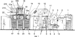
Фиг.1 является видом сбоку печатной машины с устройством для лазерного перфорирования. Figure 1 is a side view of a printing machine with a device for laser punching.
Фиг.2 показывает блок-схему процесса производства согласно настоящему изобретению. 2 shows a flowchart of a manufacturing process according to the present invention.
Фиг.3 является видом сверху печатной машины Фиг.1.Figure 3 is a top view of the printing machine of Figure 1.
Фиг.4 является частичным видом, показывающим более подробно лазерную головку устройства для лазерного перфорирования, а также аспирационное устройство, используемое, чтобы удерживать перфорируемый лист. 4 is a partial view showing in more detail the laser head of the laser punching apparatus, as well as the suction device used to hold the perforated sheet.
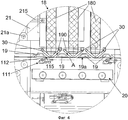
Фиг.5a и 5b являются видами в перспективе присасывающей части, которая предпочтительно расположена на краю каждой лазерной головки.5a and 5b are perspective views of a suction portion, which is preferably located on the edge of each laser head.
Фиг.6 является видом в перспективе присасывающей плиты, которая расположена на краю присасывающей части, как показано на Фиг.5a.6 is a perspective view of a suction plate that is located on the edge of the suction portion, as shown in FIG. 5a.
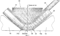
Фиг.7 является сечением присасывающей части Фиг.5а и 5b, закрепленных на краях лазерных головок устройства для лазерной перфорации.Fig.7 is a section of the suction part Figa and 5b, mounted on the edges of the laser heads of the device for laser perforation.
Изобретение будет описано в контексте конкретного воплощения, а именно печатной машины глубокой печати, оснащенной системой для лазерного перфорирования. Тем не менее, следует понимать, что этот пример не нужно рассматривать как ограничение, и что раскрытая система для лазерного перфорирования может быть применена к печатным или обрабатывающим машинам другого типа.The invention will be described in the context of a specific embodiment, namely an intaglio printing machine equipped with a laser punching system. However, it should be understood that this example should not be construed as limiting, and that the disclosed laser punching system can be applied to other types of printing or processing machines.
Дополнительно в объеме настоящего изобретения термин «лазерное перфорирование» следует понимать как обозначение того, что листы подвергают лазерному излучению и причем, по меньшей мере, часть материала листов удаляется посредством лазерного луча, чтобы создать выемку или перфорирование в толщине листов. Другими словами, «узор перфорирования», получаемый в результате «лазерного перфорирования», может быть или узором, показанным на Фиг.2 патента США № 5975583, где перфорирование сделано по всей толщине листа, узором, показанным на Фиг.3 патента США № 5975583, где удаляется только часть материала листа, или узором, который является комбинацией этих двух узоров.Additionally, within the scope of the present invention, the term “laser perforation” is to be understood as indicating that the sheets are subjected to laser radiation and that at least a portion of the sheet material is removed by means of a laser beam to create a recess or perforation in the thickness of the sheets. In other words, the “perforation pattern” resulting from “laser perforation” can be either the pattern shown in FIG. 2 of US Pat. No. 5,975,583, where the perforation is made over the entire thickness of the sheet, the pattern shown in FIG. 3 of US Pat. No. 5,975,583 where only part of the sheet material is removed, or by a pattern that is a combination of these two patterns.
На Фиг.1 проиллюстрирована печатная машина, оснащенная системой для лазерного перфорирования, причем упомянутая машина подходит для выполнения процесса, представленного на Фиг.2. Показанная печатная машина, в качестве не ограничивающего примера, является печатной машиной глубокой печати такого типа, который известен, например, из патента США № 5062359. Поэтому этот патент включен посредством ссылок в настоящую заявку в отношении раскрытия упомянутой печатной машины глубокой печати. Машина содержит устройство 1 подачи листов, которое подает последовательные листы на ролик 2 конвейера. Листы затем передаются с этого ролика 2 на печатный цилиндр 3 и удерживаются захватами, расположенными в углублениях упомянутого цилиндра 3, как известно из данной области техники. Этот печатный цилиндр 3 взаимодействует с цилиндром 4 с печатной формой, который содержит гравированные печатные формы, равномерно распределенные вокруг цилиндра, причем три печатные формы показаны в примере на Фиг.1. Дополнительно присутствует подборочный цилиндр 5, контактирующий с цилиндром 4 с печатной формой для опосредованного накатывания краски на цилиндр 4 с печатной формой. Подборочный цилиндр 5 имеет эластичную поверхность и оснащен двумя офсетными резинотканевыми пластинами. Вдоль периферии подборочного цилиндра 5 и в контакте с этим цилиндром закреплены селективные раскатные цилиндры 6, на каждый из которых накатывается краска при помощи их собственного устройства 7 для наката краски. Краска различных цветов передается с селективных раскатных цилиндров 6 на подборочный цилиндр 5, где она собирается и после этого передается на поверхность цилиндра 4 с печатной формой.Figure 1 illustrates a printing machine equipped with a system for laser punching, and said machine is suitable for performing the process shown in Figure 2. The shown press, by way of non-limiting example, is an intaglio printing press of the type that is known, for example, from US Pat. No. 5,063,259. Therefore, this patent is incorporated by reference into the present application with respect to the disclosure of said intaglio printing press. The machine comprises a
В этой машине также присутствует устройство для прямого наката краски для непосредственного накатывания краски на цилиндр 4 с печатной формой. Это устройство для прямого наката краски содержит селективный раскатный цилиндр 8 и связанное с ним устройство 7 для наката краски. Дополнительно присутствует расположенное на периферии цилиндра 4 с печатной формой ниже прямого цветного раскатного цилиндра 8 относительно направления вращения цилиндра 4 с печатной формой устройство 10 для удаления краски, которое очищает поверхность гравированных печатных форм вне оттисков с клише глубокой печати и которое вдавливает краску в оттиски с клише печатных форм до процесса печати.In this machine there is also a device for direct rolling of ink for direct rolling of ink on the
Как показано на Фиг.1, устройства 7 для наката краски расположены на подвижной каретке 9, которая может быть отодвинута от остальной части печатного устройства, как показано пунктирными линиями на Фиг.1. As shown in FIG. 1,
Последовательные листы, которые удерживаются на периферии печатного цилиндра 3, проходят через зону печатного контакта, которая расположена между печатным цилиндром 3 и цилиндром 4 с печатной формой, и получают оттиск глубокой печати. Когда печать закончена, последовательные напечатанные листы вынимают из системы 11 транспортировки, содержащей цепную листовыводящую систему, и транспортируют по направлению к устройству 14 доставки. В конфигурации, представленной на Фиг.1, последовательные листы транспортируются в систему 11 транспортировки таким образом, что их напечатанная сторона обращена вниз (по меньшей мере, до положения, где они опускаются в приемный стапель). До достижения устройства доставки, по существу, напечатанные последовательные листы могут, если требуется, проходить через устройство 12 контроля, которое контролирует качество печати (например, в отношении положения, совмещения, цвета, качества печати и основания печатной платы и т.д.), как делают в следующих публикациях предыдущего уровня техники WO 01/85586, WO 01/85457, EP 0796735, EP 0668577, EP 0734863, EP 0612042, EP 0582548, EP 0582547 и EP 0582546, содержание которых включено посредством ссылок в настоящую заявку в связи с процессом контроля качества напечатанных ценных бумаг.Successive sheets that are held at the periphery of the
После проверки последовательные листы можно дополнительно транспортировать через сушильное устройство 13, например UV сушилку, в котором высушивается краска.After checking, successive sheets can be further transported through a drying
Напечатанные листы затем транспортируют к устройству 14 доставки машины, причем упомянутое устройство 14 доставки содержит три приемных стапеля 15, 16, и 17 в примере на Фиг.1. Например, один стапель (например, стапель 15) может быть использован для дефектных листов, а два других стапеля (например, 16 и 17) для годных листов, причем каждый стапель заполняется альтернативно.The printed sheets are then transported to a
До накопления в приемных стапелях 15, 16 или 17 напечатанные последовательные листы передают в устройство 18 для лазерного перфорирования, содержащее множество лазерных головок 180, посредством которых выполняется микро-перфорирование способом, известным из вышеупомянутых патента США № 5975583, патентной заявки США № 2002/0027359 A1 и PCT заявки № WO 97/18092. Например, каждая лазерная головка 180 может быть аналогична лазерной головке, описанной в патенте США № 5975583, который включен в настоящее изобретение посредством ссылок.Prior to accumulation in the receiving slides 15, 16 or 17, printed sequential sheets are transferred to a
Следовательно, последовательные листы выносятся цепной листовыводящей системой 11 перед лазерным устройством 18 таким образом, что ненапечатанная сторона обращена вверх. Устройство 18 для лазерного перфорирования предпочтительно расположено поверх устройства 14 доставки, как проиллюстрировано на Фиг.1.Consequently, successive sheets are carried out by the chain
Чтобы гарантировать, что лист, который должен быть перфорирован, с достаточной точностью расположен перед устройством 18 для лазерного перфорирования, дополнительно обеспечивают аспирационное устройство 19 с аспирационной поверхностью 19а под лазерным устройством 18, чтобы притягивать лист, который должен быть перфорирован, к аспирационной поверхности 19а во время процесса перфорирования. В примере, показанном на Фиг.1, аспирационное устройство 19 расположено между устройством 18 для лазерного перфорирования и путем транспортировки листа системы 11 транспортировки. Предпочтительно, аспирационная поверхность 19а имеет отверстия для вакуума (не проиллюстрированы) и отверстия (обозначаемые в дальнейшем ссылочной позицией 190), где лазерные лучи применяют к листу, и она параллельна направлению транспортировки листов. Поверхность листа, используемого напротив аспирационной поверхности 19а во время перфорирования, желательно и предпочтительно является поверхностью, которая не была напечатана на этой машине, чтобы избежать повреждения напечатанной поверхности.In order to ensure that the sheet to be perforated is positioned with sufficient accuracy in front of the
Второе аспирационное устройство 20 также предпочтительно обеспечивается ниже положения перфорируемого листа (то есть со стороны листов, противоположной устройству 18 для лазерного перфорирования) для очищения от паров и сгоревших во время перфорирования материалов.The
Дополнительно для технического обслуживания лазерное устройство 18 может быть повернуто боком посредством поворотного рычага 21, который прикреплен к устройству 14 доставки и который поворачивается вокруг оси 21а, как показано пунктирными линиями на Фиг.1. Предпочтительно, отклонение лазерного устройства 18 от рабочего положения и обратно может быть выполнено посредством приводного механизма, содержащего привод 210, воздействующий на лазерное устройство 18 через приводной рычаг 215.Additionally, for maintenance, the
Когда процесс перфорирования выполнен, каждый последовательный лист дополнительно транспортируется цепной листовыводящей системой 11, проходит через ролик 22 и размещается в одном из приемных стапелей 15, 16 или 17 (напечатанная сторона листов обращена наверх). Конечно, если лист имеет дефект, то он или не перфорируется, или перфорируется только в тех местах, где нет дефектов в случае, когда лист имеет на себе печать, выполненную в матричном расположении (что обычно в области использования ценных бумаг).When the punching process is completed, each sequential sheet is additionally transported by a chain sheet-feeding
Конкретным преимуществом машины, показанной на Фиг.1, является то, что устройство 18 для лазерного перфорирования может быть расположено вдоль пути транспортировки цепной листовыводящей системы 11 в положении, где транспортировка листов может быть разъединена с печатным устройством. На самом деле, управление транспортировкой листов в устройстве 14 доставки может быть разъединено с управлением печатным устройством и быть от него независимым, посредством чего избегают влияния вибраций из-за процесса печати, что важно при выполнении микро-перфорирования такого типа, который должен быть очень точным. Дополнительно тот факт, что приводы для печатного устройства и системы доставки могут быть независимы, допускает оптимальную регулировку скоростей и совмещения при осуществлении перфорирования.A particular advantage of the machine shown in FIG. 1 is that the
Дополнительно, так как устройство лазерного перфорирования встроено в печатную машину, можно избежать использования отдельных устройств для подачи бумаги, приемных стапелей и систем транспортировки, которые все требуют технического обслуживания. Также можно выиграть пространство и добавить устройство перфорирования к устройству доставки имеющейся печатной машины при блочном модулировании.Additionally, since the laser punching device is integrated in the printing press, it is possible to avoid using separate paper feeding devices, receiving slides and conveying systems that all require maintenance. You can also gain space and add a punch device to the delivery device of your existing printing press with block modulation.
Фиг.3 является видом сверху печатной машины, проиллюстрированной на Фиг.1, где можно увидеть выполнение лазерных головок 180 устройства 18 для лазерного перфорирования. На этой фигуре можно увидеть, что устройство 18 для лазерного перфорирования содержит множество лазерных головок 180 (шесть в этом примере), распределенных как поперек, так и вдоль по отношению к направлению перемещения листов. Количество лазерных головок 180 обычно зависит от количества узоров перфорирования, которые должны быть выполнены на листах. В этом конкретном примере печатная машина предназначена для печати листов ценных бумаг, таких как банкноты, причем каждый лист несет на себе множество напечатанных узоров, выполненных в матричном виде. Более конкретно, каждый лист содержит матрицу из m столбцов и n строк напечатанных узоров. Столбец определяется в этом случае как серия напечатанных узоров, выровненных вдоль направления перемещения листов, тогда как строка определяется как серия напечатанных узоров, выровненных вдоль направления, перпендикулярного направлению перемещения листов. Размер матрицы напечатанных узоров может быть изменен и обычно достигает максимального размера из шести столбцов на десять строк (то есть шестьдесят напечатанных узоров на один лист). Шесть лазерных головок 180, таким образом, обеспечены в этом конкретном примере, чтобы иметь возможность выполнить узор перфорирования в каждом столбце напечатанных узоров вплоть до шести на одном листе. Понятно, что каждая лазерная головка 180 будет активироваться несколько раз во время перфорирования листа, чтобы обеспечить узором перфорирования каждую строку напечатанных узоров. Это выполнение, конечно, более экономично, чем обеспечение устройства для лазерного перфорирования, которое содержит столько лазерных головок, сколько присутствует напечатанных узоров на листах.Figure 3 is a top view of the printing machine illustrated in Figure 1, where you can see the implementation of the laser heads 180 of the
В этом воплощении шесть лазерных головок 180 распределены в двухмерной области (каждая лазерная головка предназначена для конкретного столбца напечатанных узоров на листах, как упомянуто выше) вместо выравнивания вдоль обычной строки. Следует понимать, что такое выполнение может быть полностью предусмотрено, а обеспеченный размер каждой лазерной головки 180 допускает более компактное выполнение.In this embodiment, six laser heads 180 are distributed in a two-dimensional region (each laser head is for a particular column of printed patterns on sheets, as mentioned above) instead of aligning along a normal line. It should be understood that such an implementation can be fully provided, and the provided size of each
Предпочтительно, положение каждой лазерной головки 180 может быть индивидуально настроено перпендикулярно направлению перемещения листов, для каждой лазерной головки 180, чтобы приспособить положение лазерной головки 180 к количеству напечатанных узоров на одном листе и к положению каждого напечатанного узора, когда кто-либо хочет применить узор перфорирования. Это может быть достигнуто закреплением каждой лазерной головки 180 на опорной балке (не показана), расположенной перпендикулярно направлению перемещения листов. Дополнительно настройка положения каждой лазерной головки 180 может быть сделана вручную или, предпочтительно, посредством полуавтоматического механизма настройки, содержащего электромотор или тому подобное, чтобы передвигать соответствующую лазерную головку 180 перпендикулярно вдоль их опорных балок.Preferably, the position of each
Кроме того, следует понимать, что достаточно снабдить устройство для лазерного перфорирования таким количеством лазерных головок, которое требуется, чтобы покрыть максимальное количество столбцов напечатанных узоров на одном листе (обычно шесть). В зависимости от действительного количества напечатанных узоров на одном листе, необходимо затем только расположить и активировать требуемое количество лазерных головок, чтобы покрыть требуемое количество столбцов напечатанных узоров. Например, если размер матрицы напечатанных узоров должен быть равным только пяти столбцам на девять строк, тогда одна из шести лазерных головок 180 может быть просто деактивирована, тогда как оставшиеся пять располагают в положениях, соответствующих пяти столбцам напечатанных узоров, для перфорирования, причем каждую из пяти оставшихся лазерных головок активируют девять раз на одном листе, чтобы покрыть все строки напечатанных узоров.In addition, it should be understood that it is sufficient to equip the laser punching device with as many laser heads as is necessary to cover the maximum number of columns of printed patterns on one sheet (usually six). Depending on the actual number of printed patterns on one sheet, then you only need to position and activate the required number of laser heads to cover the required number of columns of printed patterns. For example, if the matrix size of the printed patterns should be equal to only five columns per nine lines, then one of the six laser heads 180 can simply be deactivated, while the remaining five are located in the positions corresponding to the five columns of the printed patterns for punching, each of five The remaining laser heads are activated nine times on one sheet to cover all lines of printed patterns.
Обычно присутствует устройство управления (обозначенное ссылочной позицией 185 на Фиг.3), связанное с устройством 18 для лазерного перфорирования, чтобы настраивать требуемые рабочие параметры различных лазерных головок 180, такие как время запуска и продолжительность работы, выходная мощность и т.д.Typically, there is a control device (indicated by 185 at FIG. 3) associated with the
Фиг.4 является увеличенным видом области (обозначенной пунктирной окружностью на Фиг.1), где выполняется процесс перфорирования и которая более подробно показывает концы лазерных головок 180 и конфигурации первого аспирационного устройства 19. Как показано на Фиг.4, лист, который должен быть перфорирован (обозначенный позицией А на Фиг.4), удерживается своей ведущей кромкой штангой 111 с захватами, имеющей множество захватов 112 (цепная листовыводящая система 11, содержащая множество разнесенных штанг 111 с захватами, как известно из данной области техники) и транспортируется в положение перед устройством 18 перфорирования. Как уже упоминалось выше, ненапечатанная сторона листа А притягивается первым аспирационным устройством 19 к аспирационной поверхности 19а. Во время процесса перфорирования пары и сгоревшие материалы предпочтительно удаляются с нижней стороны перфорируемого листа А при помощи второго аспирационного устройства 20. Как будет объяснено ниже, пары и сгоревшие материалы, которые являются результатом процесса перфорирования, также могут быть удалены с верхней стороны перфорируемого листа А.FIG. 4 is an enlarged view of the region (indicated by the dotted circle in FIG. 1) where the punching process is performed and which shows in more detail the ends of the laser heads 180 and the configurations of the
Как схематически проиллюстрировано на Фиг.4, первое аспирационное устройство 19 имеет отверстия 190 в положениях лазерных головок 180. Если смотреть перпендикулярно направлению перемещения листов вдоль пути транспортировки в этом примере, эти отверстия 190 предпочтительно имеют V-образную форму, причем суженная часть отверстий 190 ориентирована вниз, по направлению к листам, которые должны быть перфорированы, чтобы максимизировать рабочую область присасывающей поверхности 19а. Чем больше присасывающая поверхность 19а, тем лучше листы будут удерживаться во время процесса перфорирования, посредством чего уменьшаются проблемы рассовмещения. Конечно, V-образная форма может быть также по-другому ориентирована, при этом суженные части отверстий 190 все еще ориентированы вниз.As schematically illustrated in FIG. 4, the
Предпочтительно, чтобы улучшить наложение листов на присасывающую поверхность 19а, особенно ведущую кромку листов, каждая штанга 111 с захватами дополнительно снабжена рядом 115 щеток, расположенных почти сразу после захватов 112 (выше захватов 112 относительно направления перемещения листов), чтобы прижимать листы к присасывающей поверхности 19а. На самом деле, следует понимать, что положение, в котором ведущая кромка листа А захватывается захватами 112, находится несколько ниже присасывающей поверхности 19а, это пространство между присасывающей поверхностью 19а и захватами 112 требуется, чтобы допустить проход захватов 112 перед присасывающей поверхностью 19а. Следовательно, листу требуется определенное расстояние, чтобы вытянуть его из положения, в котором он захвачен, в положение, в котором он правильно притянут к присасывающей поверхности 19а. Благодаря щеткам 115 непосредственно после положения, в котором ведущая кромка листа захвачена захватами 112, к листу прикладывается давление, посредством которого уменьшается до минимума расстояние, необходимое листу для правильного притяжения к присасывающей поверхности 19а. Preferably, in order to improve the overlap of sheets on the
Предпочтительно, чтобы дополнительно улучшить расположение листа, притягиваемого к присасывающей поверхности 19а во время процесса перфорирования, каждая лазерная головка 180 дополнительно снабжена на своем краю дополнительной присасывающей частью 30. Эта присасывающая часть 30 схематически проиллюстрирована на Фиг.4 и более подробно показана на фигурах 5а, 5b и 7. Эта присасывающая часть 30 имеет два назначения. Во-первых, целью этой дополнительной присасывающей части является дополнительное увеличение эффективной области присасывающей поверхности 19а. Другой целью этой дополнительной присасывающей части 30 является очищение от паров и сгоревших материалов верхней стороны листов аналогично второму аспирационному устройству 20.Preferably, in order to further improve the arrangement of the sheet attracted to the
Как показано на Фиг.5а, 5b и 7, присасывающая часть 30 содержит участок 31 корпуса, который соединен с краем соответствующей лазерной головки 180. Этот участок 31 корпуса открыт как с верхнего, так и с нижнего края, и обычно имеет коническую форму. Нижний край участка 31 корпуса включает апертуру 31а, через которую направляют лазерный луч (лазерный луч схематически проиллюстрирован на Фиг.7 при помощи толстой линии). Присасывающая часть 30 дополнительно включает V-образную трубу 32 для очистки, которая образует нераздельную часть участка 31 корпуса. Апертура 31а участка 31 корпуса сообщается с трубой 32 для очистки, причем нижний край трубы 32 для очистки аналогично снабжен апертурой 32а, через которую может пройти лазерный луч. Воздух всасывается или (вдувается) в трубу 32 для очистки, чтобы удалить пары и сгоревшие материалы, которые являются результатом процесса перфорирования.As shown in FIGS. 5a, 5b and 7, the
Дополнительно присасывающая часть 30 дополнительно включает аспирационную трубу 34, которая расположена возле трубы 32 для очистки и которая предпочтительно образует нераздельную часть участка 31 корпуса и трубы 32 для очистки. Эта аспирационная труба 34 аналогично имеет на своем нижнем краю апертуру 34а, которая расположена возле апертуры 32а трубы для очистки (см. Фиг.5b).Additionally, the
Как показано на Фиг.5b, нижний участок присасывающей части 30 имеет форму прямоугольного плоского участка 33, плоскость которого параллельна присасывающей поверхности 19а. И апертура 32а на нижнем краю V-образной трубы 32 для очистки и апертура 34а на нижнем краю аспирационной трубы 34 открыты в этом плоском участке 33.As shown in FIG. 5b, the lower portion of the
Как проиллюстрировано на Фиг.5а, плоский участок 33 имеет присасывающую плиту 35, которая имеет соответствующую прямоугольную плоскую форму (см. также Фиг.6). Как показано на Фиг.7, нижняя поверхность присасывающей плиты 35 находится на одном уровне с присасывающей поверхностью 19а аспирационного устройства 19, чтобы таким образом создавать почти сплошную присасывающую поверхность для листов. Ссылаясь на Фиг.5а и 6, можно увидеть, что присасывающая плита 35 также снабжена апертурой 35а, которая выровнена с апертурами 31а и 32а, чтобы допустить проход лазерного луча. Присасывающая плита 35 дополнительно снабжена множеством аспирационных отверстий 35b, окружающих апертуру 35а. Как показано на Фиг.6, выемка 36, в которой открыты аспирационные отверстия 35b, образована на верхней стороне присасывающей плиты 35 таким образом, что когда присасывающая плита 35 закреплена на плоском участке 33, эта выемка 36 образует канал вокруг апертуры 35а, причем канал оперативным образом соединен через апертуру 34а с аспирационной трубой 34. Применяя вакуум в аспирационной трубе 34, можно втянуть воздух через аспирационные отверстия 35b, посредством чего к поверхности присасывающей плиты 35 притягивается лист, который должен быть перфорирован.As illustrated in FIG. 5 a, the
Таким образом, понятно, что каждая дополнительная присасывающая часть 30 с ее встроенным присасывающим механизмом предпочтительно допускает расширение аспирационной поверхности 19а аспирационного устройства 19 при помощи заполнения щелей 190, где расположены лазерные головки 180. Как аспирационное устройство 19 с его аспирационной поверхностью 19а, так и присасывающие плиты 35 присасывающих частей 30 вносят вклад в образование почти однородной присасывающей поверхности для листов, дополнительно предотвращая проблемы совмещения во время процесса перфорирования и обеспечивая расположение листов на правильном расстоянии по отношению к лазерным головкам.Thus, it is understood that each
Конечно, машина настоящего изобретения не ограничивается печатной машиной глубокой печати, представленной на Фиг.1, и могут быть рассмотрены другие машины, использующие другие печатные технологии, такие как трафаретная печать, офсетная печать и др.Of course, the machine of the present invention is not limited to the intaglio printing machine of FIG. 1, and other machines using other printing technologies, such as screen printing, offset printing, etc., can be considered.
Claims (38)
a) транспортируют последовательные листы вдоль пути транспортировки в положение перед устройством для лазерного перфорирования, при этом транспортировку листов вдоль пути транспортировки выполняют посредством цепной листовыводящей системы, содержащей средство захвата для удержания ведущей кромки листов;
b) притягивают листы к аспирационной поверхности перед устройством для лазерного перфорирования;
c) пока листы притянуты к упомянутой аспирационной поверхности, перфорируют листы посредством устройства для лазерного перфорирования.32. A production method for applying at least one punch pattern to printed sheets, in particular sheets for the production of securities, banknotes, passports, ID cards and other valuable documents, comprising the following steps, according to which:
a) transporting consecutive sheets along the conveyance path to a position in front of the laser punching apparatus, wherein transporting the sheets along the conveyance path is accomplished by a chain sheet removal system comprising gripping means for holding the leading edge of the sheets;
b) pulling the sheets to the suction surface in front of the laser punching device;
c) while the sheets are drawn to said suction surface, the sheets are perforated by means of a laser punching device.
Applications Claiming Priority (2)
| Application Number | Priority Date | Filing Date | Title |
|---|---|---|---|
| EP04009514.3 | 2004-04-22 | ||
| EP04009514A EP1588864A1 (en) | 2004-04-22 | 2004-04-22 | Printing machine with laser perforating unit |
Publications (2)
| Publication Number | Publication Date |
|---|---|
| RU2006141237A RU2006141237A (en) | 2008-06-10 |
| RU2374079C2 true RU2374079C2 (en) | 2009-11-27 |
Family
ID=34924687
Family Applications (1)
| Application Number | Title | Priority Date | Filing Date |
|---|---|---|---|
| RU2006141237/12A RU2374079C2 (en) | 2004-04-22 | 2005-04-14 | Printing machine with laser perforation |
Country Status (8)
| Country | Link |
|---|---|
| US (1) | US9849711B2 (en) |
| EP (4) | EP1588864A1 (en) |
| JP (1) | JP4988555B2 (en) |
| CN (1) | CN100540331C (en) |
| AT (2) | ATE552988T1 (en) |
| DE (1) | DE602005000223T2 (en) |
| RU (1) | RU2374079C2 (en) |
| WO (1) | WO2005102728A1 (en) |
Families Citing this family (17)
| Publication number | Priority date | Publication date | Assignee | Title |
|---|---|---|---|---|
| EP1607234A1 (en) * | 2004-06-17 | 2005-12-21 | Kba-Giori S.A. | Process and apparatus for providing markings on security papers |
| DE102005025095A1 (en) | 2005-06-01 | 2006-12-07 | Giesecke & Devrient Gmbh | Data carrier and method for its production |
| EP2045783A1 (en) * | 2007-10-02 | 2009-04-08 | Kba-Giori S.A. | Method and system for controlled production of security documents, especially banknotes |
| EP2138437A1 (en) | 2008-06-27 | 2009-12-30 | Kba-Giori S.A. | Inspection system for inspecting the quality of printed sheets |
| EP2141027A1 (en) * | 2008-07-03 | 2010-01-06 | Kba-Giori S.A. | Method and installation for applying foil material onto successive sheets |
| CA2769891C (en) | 2009-08-03 | 2016-11-22 | De La Rue International Limited | Security elements and methods of manufacture |
| EP2399745A1 (en) * | 2010-06-25 | 2011-12-28 | KBA-NotaSys SA | Inspection system for in-line inspection of printed material produced on an intaglio printing press |
| BG66604B1 (en) * | 2011-01-24 | 2017-09-26 | "Кеит" Оод | A protective perforation and method for protecting products against forgery by perforation |
| DE102011103979A1 (en) * | 2011-06-10 | 2012-12-13 | Heidelberger Druckmaschinen Ag | Trimming device for processing a sheet stack and printing press or folding machine or paper processing machine with such |
| EP2637396A1 (en) | 2012-03-07 | 2013-09-11 | KBA-NotaSys SA | Method of checking producibility of a composite security design of a security document on a line of production equipment and digital computer environment for implementing the same |
| DE102012209665A1 (en) * | 2012-06-08 | 2013-12-12 | Bundesdruckerei Gmbh | System and method for customizing security documents |
| EP2754526B1 (en) | 2012-12-05 | 2022-08-17 | Pasaban, S.A. | Laser system for cutting windows in security paper |
| JP6108070B2 (en) * | 2012-12-20 | 2017-04-05 | 大日本印刷株式会社 | Sheet-fed offset printing machine equipped with laser processing equipment |
| RU2561580C1 (en) * | 2014-05-21 | 2015-08-27 | Федеральное государственное унитарное предприятие "Научно-производственное объединение им. С.А. Лавочкина" | Method of laser perforation of multi-layer roll materials, and device for its implementation |
| US10343236B2 (en) * | 2016-06-21 | 2019-07-09 | Scientific Games International, Inc. | System and method for variable perforation profiles in a stack of lottery tickets based on fold pattern |
| US10358307B1 (en) * | 2018-03-28 | 2019-07-23 | Xerox Corporation | Leading/trailing edge detection system having vacuum belt with perforations |
| JP2022127032A (en) * | 2021-02-19 | 2022-08-31 | セイコーエプソン株式会社 | Post-processing device and printer |
Family Cites Families (41)
| Publication number | Priority date | Publication date | Assignee | Title |
|---|---|---|---|---|
| DD120156A1 (en) | 1975-06-23 | 1976-06-05 | ||
| US4027137A (en) * | 1975-09-17 | 1977-05-31 | International Business Machines Corporation | Laser drilling nozzle |
| DE2643981A1 (en) * | 1976-09-29 | 1978-03-30 | Texas Instruments Deutschland | DEVICE FOR SUCTIONING DUST DURING SCRINGING SEMI-CONDUCTOR DISCS USING LASER RAYS |
| DE3114581C2 (en) * | 1981-04-10 | 1984-01-19 | M.A.N.- Roland Druckmaschinen AG, 6050 Offenbach | Conveyor device for a sheet-fed rotary printing press |
| US4552448A (en) * | 1984-02-27 | 1985-11-12 | Xerox Corporation | Sheet transport system |
| JPS63239055A (en) * | 1986-10-13 | 1988-10-05 | Dainippon Screen Mfg Co Ltd | Multicolor offset printing method |
| US5087805A (en) * | 1990-07-06 | 1992-02-11 | Webcraft Technologies, Inc. | Printed and encoded mass distributable response piece and method of making the same |
| EP0406157B1 (en) | 1989-06-29 | 1994-05-18 | De La Rue Giori S.A. | Platen printing machine for printing security paper |
| JPH0474650A (en) * | 1990-07-17 | 1992-03-10 | Toppan Printing Co Ltd | Multicolor printing device |
| US5530562A (en) | 1992-08-06 | 1996-06-25 | De La Rue Giori S.A. | Apparatus for image acquisition with speed compensation |
| CA2100322C (en) | 1992-08-06 | 2004-06-22 | Christoph Eisenbarth | Method and apparatus for monitoring image processing operations |
| CA2100324C (en) | 1992-08-06 | 2004-09-28 | Christoph Eisenbarth | Method and apparatus for determining mis-registration |
| US5298717A (en) * | 1992-08-17 | 1994-03-29 | Derossett Jr Thomas A | Method and apparatus for laser inscription of an image on a surface |
| ATE167583T1 (en) | 1993-02-17 | 1998-07-15 | De La Rue Giori Sa | DEVICE AND METHOD FOR TESTING PRINTED MATERIAL |
| US5557311A (en) * | 1993-06-11 | 1996-09-17 | Minnesota Mining And Manufacturing Company | Multi-page signatures made using laser perforated bond papers |
| IT1269506B (en) | 1994-02-04 | 1997-04-01 | De La Rue Giori Sa | QUALITY CONTROL SYSTEM OF SHEETS PRINTED IN PARTICULAR OF VALUE CARDS |
| US5504301A (en) * | 1994-03-21 | 1996-04-02 | Laser Cut Images International, Inc. | Apparatus and method for laser engraving thin sheet-like materials |
| NL9400498A (en) * | 1994-03-29 | 1995-11-01 | Iai Bv | Patterned value carrier provided with a laser beam. |
| DE4438263C2 (en) * | 1994-10-26 | 1997-05-07 | Koenig & Bauer Albert Ag | Chain bow delivery of a rotary printing machine |
| DE4442411B4 (en) * | 1994-11-29 | 2007-05-03 | Heidelberger Druckmaschinen Ag | Method of forming paper in a printing machine |
| IT1275707B1 (en) | 1995-03-30 | 1997-10-17 | De La Rue Giori Sa | PROCEDURE FOR AUTOMATIC CHECK OF THE PRINT QUALITY OF AN IMAGE ON PAPER BY MEANS OF AN OPTOELECTRONIC DEVICE |
| JP2000501036A (en) | 1995-11-13 | 2000-02-02 | オレル・フュッスリ・バンクノート・エンジニアリング・リミテッド | Secure storage document with safety mark |
| IT1284432B1 (en) | 1996-03-22 | 1998-05-21 | De La Rue Giori Sa | PROCEDURE FOR AUTOMATIC CHECK OF THE PRINT QUALITY OF A POLYCHROME IMAGE |
| NL1004433C2 (en) | 1996-11-05 | 1998-05-08 | Iai Bv | Security feature in the form of a perforation pattern. |
| US6090330A (en) * | 1997-02-06 | 2000-07-18 | Matsushita Electric Industrial Co., Ltd. | Laser processing method |
| IT1291187B1 (en) * | 1997-03-12 | 1998-12-29 | Crea Srl | LASER CUTTING SHEET METAL EQUIPMENT |
| DE19757163A1 (en) * | 1997-12-20 | 1999-06-24 | Heidelberger Druckmasch Ag | Sheet printing machine with post-processing unit |
| JPH11255419A (en) * | 1998-03-11 | 1999-09-21 | Canon Inc | Sheet puncher and image formation device |
| DE19928848A1 (en) | 1999-06-24 | 2000-12-28 | Sator Laser Gmbh | Cutting equipment for paper or plastic strips, especially bottle labels, has steerable laser on one side of strip and perforated conveyer belt on other |
| US6477950B1 (en) * | 2000-04-12 | 2002-11-12 | Michael Alan Feilen | Apparatus and method for duplex printing of a sheet-like substrate |
| KR100680732B1 (en) | 2000-05-08 | 2007-02-09 | 케이비에이-지오리 에스.에이. | Installation for treating sheets of printed paper |
| CA2407844A1 (en) | 2000-05-08 | 2002-10-31 | Kba-Giori S.A. | Device for conveying sheet-like material |
| JP4950374B2 (en) * | 2000-06-23 | 2012-06-13 | 株式会社小森コーポレーション | Sheet-like object identification method and identification apparatus |
| FR2825172A1 (en) * | 2001-05-28 | 2002-11-29 | Claude Calafell | Non reproducible perforated code or encryption marking of commercial papers by laser, in which paper is continuously fed under laser beam controlled by micro-computer programmed to set authenticating protocols for beam |
| JP3908519B2 (en) * | 2001-11-28 | 2007-04-25 | トッパン・フォームズ株式会社 | Laser processing system |
| JP2003225786A (en) * | 2002-01-30 | 2003-08-12 | Uht Corp | Laser beam machining unit and machining device equipped therewith |
| JP2003260578A (en) * | 2002-03-07 | 2003-09-16 | Printing Bureau Ministry Of Finance | Booklet boring/carrying device |
| US20030222057A1 (en) * | 2002-06-03 | 2003-12-04 | Gerety Eugene P. | Laser perforator for music media |
| US20070151958A1 (en) * | 2002-12-19 | 2007-07-05 | Modra Christopher M | Laser cutting apparatus |
| EP1473107A1 (en) | 2003-05-02 | 2004-11-03 | Kba-Giori S.A. | Machine and process for cutting openings in a substrate |
| JP2005271238A (en) | 2004-03-23 | 2005-10-06 | Komori Corp | Drilling device of printing machine |
-
2004
- 2004-04-22 EP EP04009514A patent/EP1588864A1/en not_active Withdrawn
-
2005
- 2005-04-14 AT AT06009803T patent/ATE552988T1/en active
- 2005-04-14 CN CNB2005800124037A patent/CN100540331C/en not_active Expired - Fee Related
- 2005-04-14 EP EP06009803A patent/EP1747904B1/en not_active Not-in-force
- 2005-04-14 EP EP05718496A patent/EP1613485B1/en not_active Not-in-force
- 2005-04-14 JP JP2007509000A patent/JP4988555B2/en not_active Expired - Fee Related
- 2005-04-14 EP EP10182263A patent/EP2305488A1/en not_active Withdrawn
- 2005-04-14 US US11/578,224 patent/US9849711B2/en not_active Expired - Fee Related
- 2005-04-14 WO PCT/IB2005/001058 patent/WO2005102728A1/en active Application Filing
- 2005-04-14 AT AT05718496T patent/ATE344151T1/en active
- 2005-04-14 RU RU2006141237/12A patent/RU2374079C2/en not_active IP Right Cessation
- 2005-04-14 DE DE602005000223T patent/DE602005000223T2/en active Active
Also Published As
| Publication number | Publication date |
|---|---|
| JP4988555B2 (en) | 2012-08-01 |
| ATE552988T1 (en) | 2012-04-15 |
| EP1613485B1 (en) | 2006-11-02 |
| EP2305488A1 (en) | 2011-04-06 |
| WO2005102728A1 (en) | 2005-11-03 |
| EP1747904B1 (en) | 2012-04-11 |
| RU2006141237A (en) | 2008-06-10 |
| DE602005000223D1 (en) | 2006-12-14 |
| CN1950216A (en) | 2007-04-18 |
| ATE344151T1 (en) | 2006-11-15 |
| US20070222206A1 (en) | 2007-09-27 |
| EP1747904A1 (en) | 2007-01-31 |
| US9849711B2 (en) | 2017-12-26 |
| JP2008500901A (en) | 2008-01-17 |
| EP1588864A1 (en) | 2005-10-26 |
| CN100540331C (en) | 2009-09-16 |
| EP1613485A1 (en) | 2006-01-11 |
| DE602005000223T2 (en) | 2007-09-06 |
Similar Documents
| Publication | Publication Date | Title |
|---|---|---|
| RU2374079C2 (en) | Printing machine with laser perforation | |
| JP4272561B2 (en) | Image inspection system for printing press | |
| EP1622739B1 (en) | Machine and process for cutting openings in a substrate | |
| EP1818177B1 (en) | Sheet rotary printing press | |
| US7677171B2 (en) | Printing machine and process for printing including a chain gripper system | |
| RU2572171C2 (en) | Control system for inline inspection of printed material produced on gravure printing machine | |
| JPH11320832A (en) | Feeding apparatus provided at sheet-fed rotary printer | |
| US10717269B2 (en) | Print quality examination device | |
| CN100493908C (en) | Printing control scale, printing device and printing method | |
| CN100478171C (en) | Drilling apparatus of printing press | |
| US7384495B2 (en) | Machine for applying and cutting strips of laminate | |
| RU2309834C2 (en) | Device for cutting of holes in base | |
| JP2006346992A5 (en) | ||
| US11813840B2 (en) | Print control strip, substrate, and method for controlling by open-loop control and/or closed-loop control at least one component of a processing machine | |
| JP2001150637A (en) | Intermediate cylinder for sheet press | |
| JP2008018527A (en) | Separation mechanism for portion to be cut |
Legal Events
| Date | Code | Title | Description |
|---|---|---|---|
| PD4A | Correction of name of patent owner | ||
| MM4A | The patent is invalid due to non-payment of fees |
Effective date: 20200415 |