RU2370373C2 - Device for cartridge interlocking and release - Google Patents
Device for cartridge interlocking and release Download PDFInfo
- Publication number
- RU2370373C2 RU2370373C2 RU2007108773/12A RU2007108773A RU2370373C2 RU 2370373 C2 RU2370373 C2 RU 2370373C2 RU 2007108773/12 A RU2007108773/12 A RU 2007108773/12A RU 2007108773 A RU2007108773 A RU 2007108773A RU 2370373 C2 RU2370373 C2 RU 2370373C2
- Authority
- RU
- Russia
- Prior art keywords
- cartridge
- cassette
- ejector
- receiving section
- label printer
- Prior art date
Links
- 230000007246 mechanism Effects 0.000 claims abstract description 93
- 238000000034 method Methods 0.000 claims abstract description 5
- 238000013016 damping Methods 0.000 claims description 53
- 238000007639 printing Methods 0.000 claims description 24
- 238000003780 insertion Methods 0.000 claims description 17
- 230000037431 insertion Effects 0.000 claims description 17
- 230000000903 blocking effect Effects 0.000 claims description 16
- 230000000295 complement effect Effects 0.000 claims description 3
- 230000003993 interaction Effects 0.000 claims 2
- 230000001154 acute effect Effects 0.000 claims 1
- 230000000694 effects Effects 0.000 abstract 1
- 230000001141 propulsive effect Effects 0.000 abstract 1
- 239000000126 substance Substances 0.000 abstract 1
- 238000000926 separation method Methods 0.000 description 7
- 239000010410 layer Substances 0.000 description 5
- 239000006096 absorbing agent Substances 0.000 description 3
- 238000010586 diagram Methods 0.000 description 3
- 238000009434 installation Methods 0.000 description 3
- 238000004519 manufacturing process Methods 0.000 description 3
- 230000035939 shock Effects 0.000 description 3
- 230000009471 action Effects 0.000 description 2
- 239000011241 protective layer Substances 0.000 description 2
- 230000037303 wrinkles Effects 0.000 description 2
- 239000012790 adhesive layer Substances 0.000 description 1
- 230000008901 benefit Effects 0.000 description 1
- 230000015572 biosynthetic process Effects 0.000 description 1
- 238000010276 construction Methods 0.000 description 1
- 230000008878 coupling Effects 0.000 description 1
- 238000010168 coupling process Methods 0.000 description 1
- 238000005859 coupling reaction Methods 0.000 description 1
- 238000006073 displacement reaction Methods 0.000 description 1
- 230000009467 reduction Effects 0.000 description 1
Images


Classifications
-
- B—PERFORMING OPERATIONS; TRANSPORTING
- B41—PRINTING; LINING MACHINES; TYPEWRITERS; STAMPS
- B41J—TYPEWRITERS; SELECTIVE PRINTING MECHANISMS, i.e. MECHANISMS PRINTING OTHERWISE THAN FROM A FORME; CORRECTION OF TYPOGRAPHICAL ERRORS
- B41J32/00—Ink-ribbon cartridges
-
- B—PERFORMING OPERATIONS; TRANSPORTING
- B41—PRINTING; LINING MACHINES; TYPEWRITERS; STAMPS
- B41J—TYPEWRITERS; SELECTIVE PRINTING MECHANISMS, i.e. MECHANISMS PRINTING OTHERWISE THAN FROM A FORME; CORRECTION OF TYPOGRAPHICAL ERRORS
- B41J15/00—Devices or arrangements of selective printing mechanisms, e.g. ink-jet printers or thermal printers, specially adapted for supporting or handling copy material in continuous form, e.g. webs
- B41J15/04—Supporting, feeding, or guiding devices; Mountings for web rolls or spindles
- B41J15/044—Cassettes or cartridges containing continuous copy material, tape, for setting into printing devices
-
- B—PERFORMING OPERATIONS; TRANSPORTING
- B41—PRINTING; LINING MACHINES; TYPEWRITERS; STAMPS
- B41J—TYPEWRITERS; SELECTIVE PRINTING MECHANISMS, i.e. MECHANISMS PRINTING OTHERWISE THAN FROM A FORME; CORRECTION OF TYPOGRAPHICAL ERRORS
- B41J3/00—Typewriters or selective printing or marking mechanisms characterised by the purpose for which they are constructed
- B41J3/407—Typewriters or selective printing or marking mechanisms characterised by the purpose for which they are constructed for marking on special material
- B41J3/4075—Tape printers; Label printers
Landscapes
- Handling Of Continuous Sheets Of Paper (AREA)
- Impression-Transfer Materials And Handling Thereof (AREA)
- Handling Of Sheets (AREA)
- Automatic Tape Cassette Changers (AREA)
- Feeding And Guiding Record Carriers (AREA)
- Labeling Devices (AREA)
- Printers Characterized By Their Purpose (AREA)
- Sheets, Magazines, And Separation Thereof (AREA)
Abstract
Description
Область техники, к которой относится изобретениеFIELD OF THE INVENTION
Настоящее изобретение относится к принтеру для печати этикеток и, в частности, касается устройства для блокировки кассеты в принтере для печати этикеток и выбрасывания кассеты.The present invention relates to a printer for printing labels and, in particular, relates to a device for locking the cartridge in the printer for printing labels and ejecting the cartridge.
Уровень техникиState of the art
Обычно принтеры для печати этикеток используют рулон ленты, содержащийся на кассете. Лента содержит приемный слой для изображения и защитный слой, которые скрепляются друг с другом с помощью липкого слоя. Такие принтеры для печати этикеток включают режущее устройство для отрезания части ленты, после того как изображение отпечатывается на приемном слое для изображения, с тем чтобы часть ленты, содержащая изображение, могла быть использована как этикетка. После отрезания ленты отрезанная часть вытягивается из принтера через прорезь в корпусе принтера. Затем защитный слой может быть удален, когда приемный слой изображения прикрепляется к объекту с помощью липкого слоя.Typically, label printers use a roll of tape contained on a cassette. The tape contains a receiving layer for the image and a protective layer, which are bonded to each other using an adhesive layer. Such label printers include a cutting device for cutting off a portion of the tape after the image is printed on the image receiving layer so that the portion of the tape containing the image can be used as a label. After cutting the ribbon, the cut portion is pulled out of the printer through a slot in the printer body. Then, the protective layer can be removed when the receiving layer of the image is attached to the object using the sticky layer.
Принтер для печати этикеток содержит секцию приема кассеты. Для совместной работы с запасом ленты в секции приема кассеты имеется печатающая головка. В секции приема кассеты может также присутствовать опорный валик, расположенный напротив печатающей головки. Во время печати печатающая головка взаимодействует с опорным валиком и движущейся между ними лентой. Опорный валик может приводиться в движение двигателем для протяжки ленты во время печати. В качестве альтернативы опорный валик может быть свободно вращаемым, а для протяжки ленты может использоваться дополнительный приводной ролик.The label printer includes a cartridge receiving section. To work together with the tape supply, a print head is provided in the cassette receiving section. In the cassette receiving section, a support roller located opposite the print head may also be present. During printing, the print head interacts with the platen roller and the ribbon moving between them. The platen roller can be driven by the motor to pull the ribbon during printing. Alternatively, the support roller can be freely rotated, and an additional drive roller can be used to pull the tape.
В альтернативном варианте внутри кассеты может находиться опорный валик. В такой конструкции лента находится в контакте с поверхностью опорного валика. Опорный валик в кассете взаимодействует с приводным механизмом в секции приема кассеты для протягивания ленты во время печати. В качестве альтернативы опорный валик выполняется свободно вращаемым, а для протяжки ленты используется дополнительный приводной ролик. Во время печати печатающая головка в секции приема кассеты взаимодействует с опорным валиком в кассете для продвижения ленты.Alternatively, a support roller may be located inside the cassette. In this design, the tape is in contact with the surface of the platen roller. The support roller in the cartridge interacts with a drive mechanism in the cartridge receiving section for pulling the tape during printing. As an alternative, the back-up roll is freely rotatable, and an additional drive roller is used to pull the tape. During printing, the print head in the cassette receiving section cooperates with the support roller in the cassette to advance the ribbon.
В одном варианте устройства печатающая головка перемещается между нерабочим и печатающим положением. В альтернативном устройстве опорный валик перемещается между нерабочим и печатающим положением. Существует устройство, в котором и печатающая головка и опорный валик перемещаются для достижения неработающего и печатающего положений.In one embodiment of the device, the print head moves between the idle position and the print position. In an alternative arrangement, the platen roller is moved between the idle position and the printing position. There is a device in which both the print head and the platen roller are moved to achieve idle and print positions.
Лента может быть лентой термического типа, когда печать осуществляется путем приложения теплоты от печатающего элемента к печатающей головке. Или может использоваться красящая лента, где краска переносится с ленты на воспринимающую изображение ленту при приложении теплоты к красящей ленте через печатающий элемент печатающей головки. Вместо сплошной ленты кассета может использовать рулон с высеченными этикетками.The ribbon may be a thermal ribbon when printing is carried out by applying heat from the printing element to the print head. Or, an ink ribbon can be used, where ink is transferred from the ink ribbon to the image receiving tape when heat is applied to the ink ribbon through the printhead of the print head. Instead of a continuous tape, the cassette can use a roll with carved labels.
Во всех описанных выше устройствах существует следующая проблема: для хорошего качества печати лента и/или красящая лента должны быть правильно выровнены с печатающей головкой во время печати. Более того, лента должна оставаться правильно выровненной с печатающей головкой во время печати и должна плавно проходить мимо головки для обеспечения хорошего качества печати. Чтобы обеспечить это в данном случае, желательно избегать перемещения кассеты во время печати. Кроме того, положение кассеты в секции приема кассеты должно быть заранее определенным и воспроизводимым всякий раз при вставлении кассеты в секцию приема кассеты.In all of the devices described above, the following problem exists: for good print quality, the ribbon and / or ink ribbon must be aligned correctly with the print head during printing. Moreover, the ribbon should remain correctly aligned with the print head during printing and should pass smoothly past the head to ensure good print quality. To ensure this in this case, it is advisable to avoid moving the cassette during printing. In addition, the position of the cartridge in the cartridge receiving section must be predetermined and reproducible whenever a cartridge is inserted into the cartridge receiving section.
В существующих устройствах это достигается путем введения одного или более продольных направляющих стержней, которые выступают из дна секции приема кассеты и взаимодействуют с одной или более бобинами с лентой/красящей лентой и/или приводным роликом в кассете. Расположение кассеты на этих удлиненных элементах обеспечивает то, что всякий раз кассета вставляется приблизительно в одно и то же положение в секции приема кассеты. Тем не менее, в таких устройствах высота кассеты может изменяться, если кассета не до конца вставлена в секцию приема кассеты. Кроме того, всегда остается некоторое количество свободного хода между удлиненными элементами и бобинами в кассете. Соответственно, кассета может в ограниченных пределах перемещаться в секции приема кассеты. Это будет приводить к неправильному выравниванию ленты и печатающей головки во время печати. Если кассета движется при печати, лента может заминаться или образовывать складки, что ведет к плохому качеству печати и, в худшем случае, к застреванию ленты в механизме, что может привести к поломке подающего устройства ленты и/или принтера.In existing devices, this is achieved by introducing one or more longitudinal guide rods that protrude from the bottom of the cartridge receiving section and interact with one or more reels with a ribbon / ink ribbon and / or drive roller in the cartridge. The location of the cartridge on these elongated elements ensures that each time the cartridge is inserted at approximately the same position in the receiving section of the cartridge. However, in such devices, the height of the cartridge may vary if the cartridge is not fully inserted into the cartridge receiving section. In addition, there is always a certain amount of free play between the elongated elements and the reels in the cassette. Accordingly, the cassette can move to a limited extent in the cassette receiving section. This will result in improper alignment of the ribbon and print head during printing. If the cassette moves during printing, the ribbon may wrinkle or wrinkle, resulting in poor print quality and, in the worst case, jamming of the ribbon in the mechanism, which could lead to damage to the ribbon feeder and / or printer.
Проблема усугубляется в переносных принтерах, которые могут перемещаться во время печати. В таких устройствах строгая фиксация кассеты во время печати даже более важна.The problem is exacerbated by portable printers that can move around during printing. In such devices, strict fixing of the cartridge during printing is even more important.
В патенте РСТ/ЕР/014990 описаны два типа механизма блокировки кассеты. В устройстве, приведенном на фиг.11а этого документа, показана секция приема кассеты, в которой кассета с этикетками вставлена в направлении, перпендикулярном оси вращения подающей бобины в кассете. Секция приема кассеты содержит два элемента в виде пластин, вытянутых в направлении, параллельном направлению вставки кассеты. Пластины взаимодействуют с противоположными сторонами кассеты. Пластины подвижны, благодаря чему они раздвигаются при вставке кассеты и сдвигаются при ее фиксации. От одной из указанных пластин протягивается звездочка для взаимодействия с бобиной в кассете.PCT / EP / 014990 describes two types of cassette locking mechanism. In the device shown in FIG. 11 a of this document, a cartridge receiving section is shown in which a label cartridge is inserted in a direction perpendicular to the axis of rotation of the feeding reel in the cartridge. The cartridge receiving section contains two elements in the form of plates elongated in a direction parallel to the direction of insertion of the cartridge. The plates interact with opposite sides of the cartridge. The plates are movable, due to which they move apart when inserting the cartridge and move when it is fixed. An asterisk extends from one of these plates to interact with the reel in the cartridge.
В другом устройстве, приведенном на фиг.15-18с в патенте PCN/EP/014990, показаны механизм со стопорным кольцом и кассета. В кассете выступы образуют полость для приема направляющего ролика принтера, к которому движется появляющаяся лента, как показано на фиг.18. На внешнем краю профиля кассеты находятся два позиционирующих ребра и три фиксирующих ребра. Назначение позиционирующих ребер - предотвратить поворот кассеты в радиальном направлении при вставке кассеты. Назначение фиксирующих ребер - предотвратить осевое перемещение кассеты из принтера после вставки.In another device, shown in FIGS. 15-18c of PCN / EP / 014990, a locking ring mechanism and a cartridge are shown. In the cassette, the protrusions form a cavity for receiving a guide roller of the printer, to which the emerging tape moves, as shown in Fig. 18. On the outer edge of the cassette profile are two positioning ribs and three fixing ribs. The purpose of the positioning ribs is to prevent the cassette from turning in the radial direction when inserting the cassette. The purpose of the locking ribs is to prevent axial movement of the cartridge from the printer after insertion.
Обычно секция приема кассеты бывает круглой в поперечном сечении, с толкающей пластиной с одной стороны и открытой с другой. Кассета устанавливается толкающей пластиной вниз. Внутренняя сторона секции приема кассеты образована стопорным кольцом. Внутренняя поверхность стопорного кольца имеет пазы для приема позиционирующих и фиксирующих ребер кассеты. Неподвижная часть секции приема кассеты располагается за стопорным кольцом. Чтобы вставить кассету, ее надо втолкнуть таким образом, чтобы каждое ребро попало в соответствующий паз. Толкающая пластина кассеты поддерживается по периферии пружинами и движется вниз при вставке.Typically, the cassette receiving section is round in cross section, with a pushing plate on one side and open on the other. The cassette is mounted with the pushing plate down. The inner side of the cassette receiving section is formed by a retaining ring. The inner surface of the retaining ring has slots for receiving the positioning and fixing ribs of the cartridge. The fixed portion of the cassette receiving section is located behind the retaining ring. To insert a cassette, it must be pushed in such a way that each rib falls into the corresponding groove. The cassette push plate is supported on the periphery by springs and moves downward when inserted.
Стопорное кольцо имеет выходную прорезь для ленты, так что лента может выходить из секции приема кассеты мимо направляющего ролика. Толкающая пластина соединяется с неподвижной частью секции приема кассеты, и стопорное кольцо отклоняется пружиной в тангенциальном направлении. Когда кассета проталкивается на нужное место, пружина заставляет стопорное кольцо вращаться по часовой стрелке относительно неподвижной части секции приема кассеты. Однако кольцо не может вращаться под действием пружины до тех пор, пока кассета не будет вставлена полностью. Это происходит потому, что во время вставки фиксирующие ребра удерживают пазы открытыми. Вращение стопорного кольца запирает кассету в нужную позицию. Когда механизм блокировки освобождается, толкающая пластина заставляет кассету двигаться вверх, выбрасывая кассету из секции приема кассеты.The retaining ring has an outlet slot for the tape so that the tape can exit the cassette receiving section past the guide roller. The push plate is connected to the fixed part of the cartridge receiving section, and the retaining ring is deflected by the spring in a tangential direction. When the cartridge is pushed to the desired location, the spring causes the retaining ring to rotate clockwise relative to the fixed part of the cartridge receiving section. However, the ring cannot rotate under the action of the spring until the cartridge is fully inserted. This is because during insertion, the locking ribs keep the grooves open. The rotation of the locking ring locks the cassette to the desired position. When the lock mechanism is released, the push plate causes the cartridge to move upward, ejecting the cartridge from the cartridge receiving section.
Раскрытие изобретенияDisclosure of invention
Цель настоящего изобретения - улучшить описанные выше механизмы стопорного кольца и толкающей пластины.The purpose of the present invention is to improve the above described mechanisms of the locking ring and pushing plate.
Согласно первому аспекту настоящего изобретения предлагается принтер для печати этикеток, содержащий секцию приема кассеты, указанная секция приема кассеты имеет основание, верхнее отверстие, расположенное напротив основания, механизм блокировки и механизм выбрасывания, выступающий из основания, указанный механизм выбрасывания имеет выбрасыватель, верхняя поверхность которого предназначена для взаимодействия с кассетой, выбрасыватель является подвижным в первом направлении, в сторону указанного основания, и склонным к перемещению во втором направлении, в сторону указанного верхнего отверстия, так что усилие на выбрасыватель, направленное в сторону указанного основания, заставляет выбрасыватель двигаться в первом направлении, а когда усилие на выбрасыватель снимается, выбрасыватель стремится двигаться во втором направлении, указанный механизм выбрасывания размещен таким образом, что когда кассета вставлена в секцию приема кассеты, выбрасыватель выдвигается в отверстие в основании кассеты.According to a first aspect of the present invention, there is provided a label printer comprising a cartridge receiving section, said cartridge receiving section having a base, an upper opening opposite the base, a locking mechanism and an ejection mechanism protruding from the base, said ejection mechanism having an ejector whose upper surface is intended to interact with the cartridge, the ejector is movable in the first direction, toward the indicated base, and prone to movement in the second direction, toward the specified upper hole, so that the force exerted on the ejector directed toward the base causes the ejector to move in the first direction, and when the force on the ejector is removed, the ejector tends to move in the second direction, the indicated ejection mechanism is placed in such a way that when the cartridge is inserted in the cartridge receiving section, the ejector extends into the hole in the base of the cartridge.
Согласно второму аспекту настоящего изобретения предлагается кассета для этикеток, содержащая корпус, имеющий основание и верхнюю часть, и полость, включающую в себя отверстие в основании и поверхность выбрасывателя, расположенную между указанным отверстием и указанной верхней частью, для взаимодействия с выбрасывателем, выступающим из основания секции приема кассеты принтера, указанная поверхность выбрасывателя установлена с возможностью приложения усилия к выбрасывателю в направлении к основанию секции приема кассеты во время вставки кассеты в секцию приема кассеты, двигающего выбрасыватель в направлении основания секции приема кассеты, полость в кассете выполнена таким образом, чтобы выбрасыватель располагался внутри полости кассеты, когда кассета вставлена в секцию приема кассеты.According to a second aspect of the present invention, there is provided a label cassette comprising a housing having a base and an upper part and a cavity including an opening in the base and an ejector surface disposed between said opening and said upper part for interacting with the ejector protruding from the base of the section printer cartridge receiving, the indicated ejector surface is installed with the possibility of applying force to the ejector towards the base of the cartridge receiving section during sun avki cassette into the cassette receiving bay moving the ejector towards the base of the cassette receiving section, the cavity formed in the cassette so that the ejector located within the cavity cassette when the cassette is inserted into the cassette receiving bay.
Согласно третьему аспекту настоящего изобретения предлагается принтер для печати этикеток, содержащий секцию приема кассеты, указанная секция приема кассеты имеет демпфирующий механизм, причем демпфирующий механизм выступает из боковой стенки секции приема кассеты с целью взаимодействия с зубчатой рейкой на боковой стенке кассеты.According to a third aspect of the present invention, there is provided a label printer comprising a cartridge receiving section, said cartridge receiving section having a damping mechanism, the damping mechanism protruding from the side wall of the cartridge receiving section to interact with a gear rack on the side wall of the cartridge.
Согласно четвертому аспекту настоящего изобретения предлагается кассета с этикетками, содержащая корпус с зубчатой рейкой, расположенной на боковой стороне корпуса, с целью взаимодействия с демпфирующим механизмом, выступающим из боковой стенки секции приема кассеты принтера для печати этикеток, когда кассета вставляется в принтер для печати этикеток и извлекается из него.According to a fourth aspect of the present invention, there is provided a cassette with labels comprising a casing with a gear rack located on a side of the casing for engaging with a damping mechanism protruding from the side wall of the receiving section of the cassette of the label printer when the cartridge is inserted into the label printer and extracted from it.
Согласно пятому аспекту настоящего изобретения предлагается принтер для печати этикеток, содержащий секцию приема кассеты, при этом указанная секция приема кассеты содержит стопорное кольцо, имеющее подвижную часть, которая является подвижной в первом направлении и стремится двигаться во втором направлении, указанная подвижная часть имеет один или более выступов, направленных радиально внутрь таким образом, что приложенное к ним усилие, перпендикулярное первому и второму направлениям и направленное вниз, заставляет подвижную часть стопорного кольца перемещаться в первом направлении, а когда усилие вниз снимается, подвижная часть стопорного кольца стремится перемещаться во втором направлении, указанная подвижная часть содержит, по меньшей мере, два удлиненных элемента, шарнирно соединенных друг с другом шарнирным соединением, имеющим ось вращения, перпендикулярную указанным первому и второму направлениям, указанные один или более выступов находятся, по меньшей мере, на одном из указанных, по меньшей мере, двух удлиненных элементов.According to a fifth aspect of the present invention, there is provided a label printer comprising a cartridge receiving section, said cartridge receiving section having a retaining ring having a movable part that is movable in a first direction and tends to move in a second direction, said movable part has one or more protrusions directed radially inward in such a way that the force applied to them, perpendicular to the first and second directions and directed downward, causes the movable part to axial ring move in the first direction, and when the force is removed downward, the movable part of the retaining ring tends to move in the second direction, the movable part contains at least two elongated elements, pivotally connected to each other by a pivot connection having an axis of rotation perpendicular to the specified to the first and second directions, said one or more protrusions are located on at least one of said at least two elongated elements.
Согласно шестому аспекту настоящего изобретения предлагается кассета с этикетками, содержащая корпус, имеющий основание, верхнюю часть и боковые стороны и средство блокировки, расположенное на боковой стороне корпуса, для взаимодействия с механизмом блокировки в принтере для печати этикеток, указанное средство блокировки имеет паз, проходящий от основания до верха, и блокирующую камеру в верхнем конце указанного паза, при этом паз имеет наклонную поверхность с углом наклона между 0 и 90° относительно основания, а блокирующая камера имеет участок стенки, расположенный над указанной наклонной поверхностью.According to a sixth aspect of the present invention, there is provided a label cassette comprising a housing having a base, a top and sides, and locking means located on a side of the housing for interacting with a locking mechanism in a label printer, said locking means having a groove extending from base to the top, and a blocking chamber at the upper end of the specified groove, while the groove has an inclined surface with an angle of inclination between 0 and 90 ° relative to the base, and the blocking chamber has a wall portion positioned over said sloped surface.
Согласно седьмому аспекту настоящего изобретения предлагается способ загрузки кассеты с этикетками и ее извлечения из принтера для печати этикеток, содержащего секцию приема кассеты, механизм выбрасывания и демпфирующий механизм, заключающийся в том, что кассету вставляют в секцию приема кассеты в первом направлении и извлекают из секции приема кассеты во втором направлении, при этом обеспечивают демпфирующее движение кассеты в первом и втором направлениях при вставке и извлечении кассеты соответственно.According to a seventh aspect of the present invention, there is provided a method of loading a label cartridge and removing it from a label printer including a cartridge receiving section, an ejection mechanism, and a damping mechanism, the cartridge being inserted in the cartridge receiving section in a first direction and removed from the receiving section cassettes in the second direction, while providing damping movement of the cassette in the first and second directions when inserting and removing the cassette, respectively.
Краткое описание чертежейBrief Description of the Drawings
Для лучшего понимания настоящего изобретения и иллюстрации возможных вариантов его осуществления приводятся следующие чертежи, на которых:To better understand the present invention and illustrate possible options for its implementation, the following drawings are given, in which:
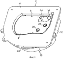
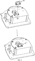
фиг.1 - перспективный вид сверху секции приема кассеты с загруженной кассетой;figure 1 is a perspective top view of the receiving section of the cartridge loaded with the cartridge;
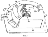
фиг.2 - перспективный вид снизу секции приема кассеты, показанной на фиг.1;figure 2 is a perspective bottom view of the receiving section of the cartridge shown in figure 1;
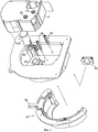
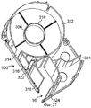
фиг.3 - перспективное изображение с пространственным разделением деталей кассеты и секции приема кассеты, показанных на фиг.1 и 2;figure 3 is a perspective image with a spatial separation of the parts of the cartridge and the receiving section of the cartridge shown in figures 1 and 2;
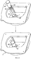
фиг.4 - конструкция выбрасывателя;figure 4 - design of the ejector;
фиг.5 - более детальная конструкция выбрасывателя;5 is a more detailed ejector design;
фиг.6 - низ секции приема кассеты и конструкция демпфирующего механизма;6 is a bottom of the receiving section of the cartridge and the design of the damping mechanism;
фиг.7 - более детальная конструкция демпфирующего механизма;7 is a more detailed design of the damping mechanism;
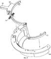
фиг.8 - перспективное изображение с пространственным разделением деталей части стопорного кольца;Fig is a perspective image with a spatial separation of the parts of the retaining ring;
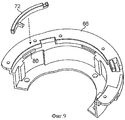
фиг.9 - другое перспективное изображение с пространственным разделением деталей части стопорного кольца;Fig.9 is another perspective image with a spatial separation of the parts of the retaining ring;
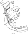
фиг.10 - еще одно перспективное изображение с пространственным разделением деталей части стопорного кольца;figure 10 is another perspective image with a spatial separation of the parts of the retaining ring;
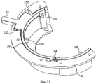
фиг.11 - полностью собранное стопорное кольцо;11 is a fully assembled retaining ring;
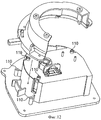
фиг.12 - процесс установки стопорного кольца на боковую поверхность секции приема кассеты;Fig - installation of the retaining ring on the side surface of the receiving section of the cartridge;
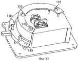
фиг.13 - стопорное кольцо, установленное на боковой поверхности секции приема кассеты;Fig. 13 is a retaining ring mounted on a side surface of a cartridge receiving section;
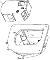
фиг.14 - вставка кассеты в секцию приема кассеты;Fig.14 - insertion of the cartridge in the receiving section of the cartridge;
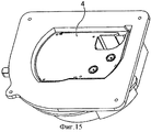
фиг.15 - кассета, вставленная в секцию приема кассеты;Fig. 15 shows a cartridge inserted in a cartridge receiving section;
фиг.16 - монтажные отверстия в секции приема кассеты для установки в корпусе принтера;Fig - mounting holes in the receiving section of the cartridge for installation in the printer;
фиг.17 - перспективный вид снизу принтера для печати этикеток, показывающий ребра для пружины растяжения и демпфирующий механизм;17 is a perspective bottom view of a label printer showing ribs for a tension spring and a damping mechanism;
фиг.18 - детальный вид демпфирующего механизма;Fig. 18 is a detailed view of a damping mechanism;
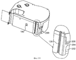
фиг.19 - перспективный вид кассеты с зубчатой рейкой на боковой поверхности, служащей для взаимодействия с демпфирующим механизмом в секции приема кассеты;Fig is a perspective view of a cassette with a gear rack on the side surface, which serves to interact with the damping mechanism in the cassette receiving section;
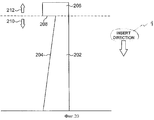
фиг.20 - схема блокирующего приспособления на кассете;Fig.20 is a diagram of a locking device on the cartridge;
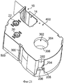
фиг.21 - перспективный вид снизу кассеты;Fig is a perspective view from below of the cartridge;
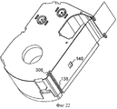
фиг.22 - перспективный вид снизу кассеты под другим углом;Fig is a perspective view from below of the cartridge at a different angle;
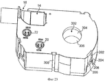
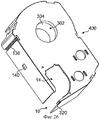
фиг.23 - перспективный вид снизу кассеты под еще одним углом;Fig is a perspective view from below of the cartridge at another angle;
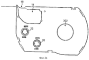
фиг.24 - вид снизу кассеты;Fig is a bottom view of the cartridge;
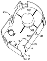
фиг.25 - перспективный вид нижнего корпуса кассеты, показывающий пространство внутри нижнего корпуса;Fig is a perspective view of the lower cassette body, showing the space inside the lower case;
фиг.26 - перспективный вид нижнего корпуса кассеты, показывающий внешний вид нижнего корпуса;FIG. 26 is a perspective view of the lower case of the cartridge showing the appearance of the lower case; FIG.
фиг.27 - перспективный вид верхней рамы корпуса кассеты, показывающий пространство внутри верхнего корпуса;Fig is a perspective view of the upper frame of the cassette, showing the space inside the upper case;
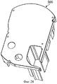
фиг.28 - перспективный вид верхнего корпуса кассеты, показывающий внешний вид верхнего корпуса.FIG. 28 is a perspective view of the upper case of the cartridge showing the appearance of the upper case.
Осуществление изобретенияThe implementation of the invention
На фиг.1 показан перспективный вид сверху секции 2 приема кассеты со вставленной в него кассетой 4. Секция 2 приема кассеты содержит верхний фланец 6, имеющий выемку, образующую отверстие 8 для приема кассеты 4. Секция 2 приема кассеты имеет основание 10 и боковую поверхность 12, протянувшуюся от основания 10 к отверстию 8. Кассета 4 содержит корпус с полостью 14 для приема печатающей головки и/или валика, когда кассета 4 установлена в принтер для печати этикеток. Сбоку на кассете 4 предусмотрено отверстие 16, через которое проходит лента для взаимодействия с печатающей головкой и валиком традиционным образом. Показанная кассета 4 содержит подающую катушку 20 красящей ленты и принимающую катушку 22 красящей ленты. Бобина с красящей лентой также находится внутри кассеты 4. Красящая лента во взаимодействии с лентой приема печати проходит через отверстие для осуществления печати. Стопорное кольцо 24 предусмотрено для блокирования кассеты 4 в печатающем положении внутри секции 2 приема кассеты.Figure 1 shows a perspective top view of the
Более детально стопорное кольцо 24 можно увидеть на фиг.2, где показан перспективный вид снизу секции 2 приема кассеты. Пружина 26 предназначена для смещения выбрасывателя в направлении, противоположном направлению вставки кассеты 4. Зубчатая рейка 28, находящаяся в нижней части выбрасывателя, взаимодействует с демпфирующим механизмом 30. Стопорное кольцо включает в себя часть, которая неподвижна относительно секции 2 приема кассеты, и другую часть, которая вращается относительно неподвижной части, вращающаяся часть имеет рычаг 32 для вращения указанной части. Неподвижная часть имеет соединительные элементы 34 для жесткого соединения с секцией приема кассеты. Основание секции приема кассеты имеет отверстие для приема пружины. Дополнительное отверстие предусмотрено для зубчатой рейки 28 выбрасывателя. Демпфирующий механизм 30 жестко соединен с нижней поверхностью основания секции приема кассеты таким образом, чтобы взаимодействовать с зубчатой рейкой 28 выбрасывателя. Нижние части двух цепных колес 36, 38 выступают сквозь основание секции приема кассеты.In more detail, the retaining
На фиг.3 показано перспективное изображение с пространственным разделением деталей секции 2 приема кассеты, стопорного кольца 24, демпфирующего механизма 30 и кассеты 4 с этикетками. Выбрасыватель 40 смонтирован в корпусе 42 на основании секции 2 приема кассеты. Выбрасыватель имеет цилиндрическую форму с верхней поверхностью, предназначенной для взаимодействия с кассетой. Пружина 44 вставляется между выбрасывателем и основанием секции приема кассеты для смещения выбрасывателя 40 в направлении, противоположном направлению вставки кассеты 4. Два удлиненных цепных колеса 36, 38 смонтированы на основании секции 2 приема кассеты для взаимодействия соответственно с принимающей катушкой 20 и подающей катушкой 22 красящей ленты. Стопорное кольцо 24 установлено на боковой поверхности секции приема кассеты. Демпфирующий механизм 30 установлен на нижней поверхности основания приема кассеты.Figure 3 shows a perspective image with a spatial separation of the parts of the receiving
На фиг.4 показан монтаж выбрасывателя 40 на основании секции приема кассеты. Цилиндрический корпус 42 на основании служит для поддержки и выравнивания выбрасывателя 40. Внешняя поверхность выбрасывателя снабжена крепежным механизмом 46 (в данном случае - защелкой) для взаимодействия с отверстием 48 в корпусе 42 выбрасывателя, с тем чтобы соединить выбрасыватель 40 с секцией приема кассеты и предотвратить полное выталкивание выбрасывателя 40 из корпуса пружиной 44. Механизм 46 защелки и отверстие 48 в корпусе выбрасывателя расположены так, чтобы выбрасыватель мог двигаться вниз против пружины 44. Когда пружина освобождается, она заставляет выбрасыватель двигаться вверх до тех пор, пока крепежный механизм не достигнет верхней части отверстия. В настоящих вариантах осуществления выбрасыватель имеет ход 20 мм.Figure 4 shows the installation of the
На фиг.5 механизм выбрасывателя показан более детально. Выбрасыватель содержит цилиндрический корпус 50, имеющий верхнюю поверхность 52, предназначенную для взаимодействия с нижней поверхностью кассеты. Удлиненная зубчатая рейка 54 идет от нижней части корпуса 50 выбрасывателя, она предназначена для взаимодействия с демпфирующим механизмом 30. На этом чертеже четко показан крепежный механизм 46, который взаимодействует с корпусом выбрасывателя в секции приема кассеты. В иллюстрируемом варианте осуществления изобретения крепежный механизм представляет собой защелку. Пружина 44 выбрасывателя взаимодействует с нижней поверхностью корпуса выбрасывателя с целью смещения выбрасывателя в направлении, противоположном направлению вставки кассеты.5, the ejector mechanism is shown in more detail. The ejector includes a
Выбрасыватель в настоящем варианте осуществления представляет собой скорее поршень, нежели толкающую пластинку, как описано в патенте РСТ/ЕР/014990. Одна отличительная особенность вариантов осуществления настоящего изобретения состоит в том, что выбрасыватель располагается между боковыми стенками секции приема кассеты предпочтительно приблизительно в центре секции приема кассеты для взаимодействия с корпусом кассеты во время вставки кассеты в секцию приема кассеты. Выбрасыватель выступает из основания секции приема кассеты и проходит в вертикальном направлении между основанием и верхним отверстием секции приема кассеты, верхняя поверхность выбрасывателя находится между основанием и верхним отверстием.The ejector in the present embodiment is a piston rather than a pushing plate, as described in PCT / EP / 014990. One distinguishing feature of the embodiments of the present invention is that the ejector is located between the side walls of the cartridge receiving section, preferably approximately in the center of the cartridge receiving section, to interact with the cartridge case when inserting the cartridge into the cartridge receiving section. The ejector protrudes from the base of the cartridge receiving section and extends vertically between the base and the upper hole of the cartridge receiving section, the upper surface of the ejector is between the base and the upper hole.
Описанный выше выбрасыватель прост по конструкции и легок в изготовлении. Компактный механизм подходит для маленьких ручных принтеров. В частности, из-за того что выбрасыватель в вариантах осуществления изобретения выступает из основания секции приема кассеты и проходит через отверстие в основании кассеты (см. подробное описание далее), необходимость в средствах монтажа и смещения по периметру секции приема кассеты, как в случае толкающей пластинки, отпадает. То есть выбрасыватели согласно вариантам осуществления настоящего изобретения располагаются, по существу, внутри кассеты, когда кассета вставлена в принтер, а не вне кассеты, действуя на ее наружную поверхность. Это ведет к уменьшению размера устройства.The ejector described above is simple in construction and easy to manufacture. The compact mechanism is suitable for small hand printers. In particular, due to the fact that the ejector in the embodiments of the invention protrudes from the base of the cartridge receiving section and passes through the hole in the cartridge base (see the detailed description below), the need for mounting and displacement tools around the cartridge receiving section, as in the case of a pushing records are falling away. That is, ejectors according to embodiments of the present invention are located essentially inside the cartridge when the cartridge is inserted into the printer, and not outside the cartridge, acting on its outer surface. This leads to a reduction in the size of the device.
В настоящих описываемых вариантах осуществления механизм выбрасывания содержит выбрасыватель и пружину, расположенную между выбрасывателем и основанием секции приема кассеты. Тем не менее, в простейшей форме выбрасывателем может быть просто средство смещения, например пружина, идущая от основания секции приема кассеты и проходящая через отверстие в основании кассеты.In the present described embodiments, the ejection mechanism comprises an ejector and a spring located between the ejector and the base of the cartridge receiving section. However, in its simplest form, the ejector may simply be a biasing means, such as a spring, coming from the base of the cartridge receiving section and passing through an opening in the cartridge base.
В описываем варианте осуществления основание кассеты и основание секции приема кассеты перпендикулярны бобине, на которой установлена лента. В альтернативной конструкции, где кассета боком вставляется в секцию приема кассеты, основание кассеты и основание секции приема кассеты параллельны бобине, на которой установлена лента.In the described embodiment, the base of the cartridge and the base of the receiving section of the cartridge are perpendicular to the reel on which the tape is mounted. In an alternative design where the cartridge is sideways inserted into the cartridge receiving section, the base of the cartridge and the base of the cartridge receiving section are parallel to the reel on which the tape is mounted.
На фиг.6 показан перспективный вид снизу секции приема кассеты. Иллюстрируется присоединение демпфирующего механизма 30. На нижней поверхности основания секции приема кассеты предусматриваются отверстия 60 для крепления демпфирующего механизма.Figure 6 shows a perspective bottom view of the cassette receiving section. The connection of the damping
На фиг.7 демпфирующий механизм показан более детально. Механизм содержит амортизатор 62 и держатель 64, служащий для соединения амортизатора с нижней поверхностью основания секции приема кассеты. Амортизатор крепится в держателе с помощью двух защелок.7, the damping mechanism is shown in more detail. The mechanism comprises a
На фиг.8 показано перспективное изображение с пространственным разделением деталей стопорного кольца. Стопорное кольцо включает в себя неподвижную раму 66 для установки на ней подвижного кольца. Подвижное кольцо содержит две части: главную часть 70 стопорного кольца и подчиненную часть 72 стопорного кольца. Пружина 74 стопорного кольца прикреплена к главной части 70 стопорного кольца и неподвижной раме 66 и служит для смещения подвижного кольца по часовой стрелке относительно неподвижной рамы 66. Главная часть 70 стопорного кольца снабжена рычагом 32, служащим для поворота подвижного кольца относительно скользящей рамы.On Fig shows a perspective image with a spatial separation of the details of the retaining ring. The retaining ring includes a fixed
Особенность конструкции, заключающаяся в том, что подвижная часть стопорного кольца состоит из нескольких частей и эти части могут перемещаться относительно друг друга, позволяет стопорному кольцу работать с кассетами различных форм.A design feature, which consists in the fact that the movable part of the retaining ring consists of several parts and these parts can be moved relative to each other, allows the retaining ring to work with cartridges of various shapes.
На фиг.9 показан другой вид стопорного кольца. Подчиненная часть 72 стопорного кольца располагается на неподвижной раме 66. Направляющее ребро 80 используется для установки и выравнивания подчиненной части 72 стопорного кольца.Figure 9 shows another view of the retaining ring. The
На фиг.10 приведена другая иллюстрация стопорного кольца. Направляющее ребро 82 предназначено для установки и выравнивания главной части 70 стопорного кольца на неподвижной раме 66.Figure 10 shows another illustration of a retaining ring. The
Неподвижная рама 66 содержит, по существу, цилиндрическую часть 84, нижний фланец 86 и верхний фланец 88, служащие для присоединения рамы к секции приема кассеты. Ступенька 90 выполнена между верхним фланцем 88 и цилиндрической частью 84 для размещения на ней подвижного кольца. Направляющее ребро 82 выполнено на ступеньке для выравнивания подвижного кольца. Отверстие 92 в верхнем фланце предусмотрено для рычага 32 стопорного кольца. Связь 94 включает в себя выступ на подчиненной части стопорного кольца и полость в главной части стопорного кольца для приема указанного выступа, хотя, разумеется, рассматриваются и альтернативные приспособления. Связь 94 обеспечивает соединение с возможностью вращения между главной и подчиненной частями стопорного кольца. Все части подвижного кольца устанавливаются на неподвижной раме, причем главная и подчиненная части подвижного кольца расположены на направляющих ребрах и соединены вместе. Подвижное кольцо смещено по часовой стрелке при помощи пружины.The fixed
На фиг.11 показан перспективный вид сверху подвижного кольца 70, установленного на неподвижной раме 66. Рычаг 32 выходит радиально наружу через отверстие в верхнем фланце 88. Рычаг 32 примыкает к поверхностям 100, 102 неподвижной рамы 66 с целью ограничения вращения подвижного кольца 70. На подвижном кольце 70 выполнены выступы 106 (один или более), направленные радиально внутрь, для взаимодействия с кассетой. Стопорное кольцо 70 показано в закрытом положении. Чтобы открыть кольцо, необходимо совершить поворот приблизительно на 4 градуса. Связь 94 между главным стопорным кольцом и подчиненным стопорным кольцом обеспечивает их неподвижное соединение.11 shows a perspective top view of a
На фиг.12 показано стопорное кольцо, устанавливаемое в секцию приема кассеты. На нижней поверхности основания и нижней поверхности верхнего фланца секции приема кассеты имеются крепежные опоры 110, служащие для установки стопорного кольца, как показано на фиг.13.12 shows a snap ring mounted in a cartridge receiving section. On the lower surface of the base and the lower surface of the upper flange of the cassette receiving section, there are mounting
На фиг.14 показана вставка кассеты 4 в секцию приема кассеты. Выступы 106 стопорного кольца выступают радиально внутрь с целью взаимодействия с корпусом кассеты. В секции приема кассеты также выполнена удлиненная направляющая 120 сбоку секции приема кассеты для выравнивания и фиксации кассеты в рабочем положении.On Fig shows the insertion of the
На фиг.15 показана кассета 4, установленная в секции приема кассеты.On Fig shows the
Кассета помещается в центре при помощи пружины выбрасывателя и выступов на стопорном кольце. Во время вставки кассеты выступы взаимодействуют с наклонной поверхностью блокирующего приспособления на корпусе кассеты (см. описание далее). При вставке каждое блокирующее приспособление на корпусе кассеты давит на наклонную поверхность выступа стопорного кольца, заставляя стопорное кольцо двигаться против часовой стрелки, преодолевая сопротивление пружины. После того как наклонная поверхность на корпусе кассеты опустится ниже выступа стопорного кольца, пружина заставляет стопорное кольцо двигаться по часовой стрелке, перемещая выступы стопорного кольца в положение над наклонной поверхностью корпуса кассеты и блокируя тем самым движение кассеты вверх. Передвигая рычаг стопорного кольца против часовой стрелки, выступы стопорного кольца движутся от положения над наклонными поверхностями на корпусе кассеты в позицию рядом с наклонными поверхностями. После этого кассета может свободно двигаться вверх под действием выбрасывателя. В предпочтительном варианте осуществления выступы стопорного кольца выполнены трапецеидальными или приблизительно трапецеидальными в поперечном сечении.The cassette is placed in the center using the ejector spring and the protrusions on the retaining ring. During insertion of the cartridge, the protrusions interact with the inclined surface of the locking device on the cartridge case (see description below). When inserted, each locking device on the cassette body presses on the inclined surface of the protrusion of the locking ring, causing the locking ring to move counterclockwise, overcoming the resistance of the spring. After the inclined surface on the cartridge case falls below the protrusion of the locking ring, the spring forces the locking ring to move clockwise, moving the protrusions of the locking ring to a position above the inclined surface of the cartridge case and thereby blocking the cartridge’s upward movement. By moving the locking ring lever counterclockwise, the protrusions of the locking ring move from a position above the inclined surfaces on the cassette body to a position near the inclined surfaces. After that, the cartridge can freely move upward under the action of the ejector. In a preferred embodiment, the protrusions of the retaining ring are made trapezoidal or approximately trapezoidal in cross section.
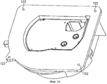
На фиг.16 показан перспективный вид секции приема кассеты с установленной кассетой. Для присоединения секции приема кассеты к корпусу принтера на верхнем фланце секции приема кассеты предусмотрены установочные отверстия 122.On Fig shows a perspective view of the receiving section of the cartridge with the cartridge installed. Mounting
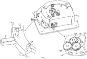
На фиг.17 показан перспективный вид снизу секции приема кассеты. Крепежное приспособление 124 предусмотрено на рычаге 32 стопорного кольца и на неподвижной раме 66 с целью установки между ними пружины, служащей для смещения подвижного кольца. Сбоку секции приема кассеты установлен демпфирующий механизм 126. Демпфирующий механизм содержит монтажную раму 128, на которой установлены два зубчатых колеса 130, с ними сцепляется демпфирующее зубчатое колесо 132 с возможностью вращения. В настоящем варианте осуществления два зубчатых колеса 130 и демпфирующее зубчатое колесо 132 установлены на промежуточной площадке 134, которая присоединяется к монтажной раме 128 с помощью защелки. Такое решение обеспечивает простоту изготовления и легкость замены деталей. Когда демпфирующий механизм 126 монтируется на боковой поверхности секции приема кассеты, два зубчатых колеса 130 выступают через отверстие в боковой поверхности секции приема кассеты, чтобы взаимодействовать с зубчатой рейкой на боковой поверхности кассеты, вставленной в отсек. Более детально это показано на фиг.18 и 19.On Fig shows a perspective bottom view of the receiving section of the cartridge. A
В показанном приспособлении демпфирующий механизм 126 соединяется с удлиненной направляющей 136. Зубчатые колеса 130 демпфирующего механизма выступают из боковой поверхности секции и выровнены вдоль удлиненной направляющей 136. Зубчатые колеса 130 входят в секцию немного больше, чем удлиненная направляющая, для взаимодействия с зубчатой рейкой 138 кассеты. Такой механизм обеспечивает дополнительную защиту для кассеты, так как он обеспечивает управляемое выбрасывание. Этот демпфирующий механизм может быть реализован вместе с демпфирующим механизмом выбрасывателя или как альтернатива демпфирующему механизму выбрасывателя. Если данный демпфирующий механизм предоставляется как альтернатива демпфирующему механизму выбрасывателя, то общая высота приспособления может быть уменьшена за счет удаления демпфирующего механизма, установленного на нижней поверхности основания секции приема кассеты.In the device shown, the damping
На фиг.19 показана кассета, на боковой поверхности которой имеется зубчатая рейка 138, служащая для взаимодействия с демпфирующим механизмом. Зубчатая рейка 138 установлена в полости. Полость предназначена для выравнивания с удлиненной направляющей 136 сбоку секции приема кассеты. Зубчатая рейка 138 сцепляется с зубчатыми колесами 130 демпфирующего механизма, которые объединены с удлиненной направляющей 136 и выровнены вдоль нее. Зубчатые колеса 130 демпфилирующего механизма должны выступать относительно удлиненной направляющей 136, чтобы взаимодействовать с зубчатой рейкой 138. Ширина и глубина удлиненной полости в кассете равны ширине и глубине удлиненной направляющей 136 в секции приема кассеты.On Fig shows a cartridge, on the side surface of which there is a
На фиг.19 также показано отверстие 140 для идентификации пробитых этикеток в кассете и блокирующее приспособление 200, расположенное сбоку кассеты и служащее для взаимодействия с выступом 106 на стопорном кольце. Блокирующее приспособление 200 содержит паз 202, имеющий дополнительную наклонную поверхность 204, предназначенную для взаимодействия с наклонной поверхностью выступа 106. Наклонная поверхность 204 имеет угол наклона от 0 до 90° (более предпочтительно между 10 и 50°) относительно направления вставки и оси вращения подающей бобины. При вставке кассеты наклонные поверхности примыкают и скользят относительно друг друга, когда кассета вталкивается вниз, со стопорным кольцом, вращающимся в первом направлении вследствие усилия, сообщаемого наклонной поверхностью 204 блокирующего приспособления на наклонной поверхности выступа 106. В конце паза 202 расположена блокирующая камера 206. Когда выступ 106 входит в камеру 206 при вставке кассеты, стопорное кольцо смещается с поворотом во втором направлении, противоположном первому, блокируя кассету в нужном положении. Блокирующая камера 206 содержит горизонтальную стенку 208 (перпендикулярную направлению вставки кассеты и оси вращения подающей бобины), расположенную вертикально над наклонной поверхностью и препятствующую выталкиванию кассеты из секции приема кассеты механизмом выбрасывания.19 also shows an
Схема блокирующего приспособления кассеты приведена на фиг.20. Схема показывает паз 202 в боковой поверхности кассеты, имеющий наклонную поверхность/стенку 204, служащую для открытия стопорного кольца при вставке кассеты в принтер для печати этикеток (направление вставки показано на фиг.20). Корпус кассеты выгодно изготовлять из двух частей (или корпусов) 210, 212, которые совмещаются при формировании корпуса кассеты, как показано на фиг.20 штриховой линией. В этом случае блокирующий паз 202 находится в нижней части 210 корпуса кассеты, а блокирующая камера 206 расположена во второй части 212 корпуса кассеты. При расположении паза и блокирующей камеры в разных частях формирование корпуса кассеты становится менее сложным.A diagram of the cassette locking device is shown in FIG. The diagram shows a
Положение блокирующей камеры в направлении ширины кассеты определяет положение кассеты в направлении вставки. Для кассет различной ширины положение блокирующей камеры может изменяться таким образом, чтобы центральная линия приемного слоя изображения совпадала с центральной линией печатающей головки.The position of the blocking chamber in the width direction of the cartridge determines the position of the cartridge in the insertion direction. For cassettes of different widths, the position of the blocking chamber can be changed so that the center line of the image receiving layer coincides with the center line of the print head.
Направляющие пазы имеют две функции: 1) позиционировать кассету и 2) направлять кассету при ее вставке.The guide grooves have two functions: 1) position the cartridge and 2) guide the cartridge when it is inserted.
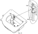
На фиг.21 показан перспективный вид кассеты снизу. Кассета содержит нижний корпус 400 и верхний корпус 500. Нижний корпус имеет отверстие 302, в котором сформирована полость с боковыми сторонами 304 и основанием 306 полости. В представленном варианте осуществления полость имеет цилиндрическую форму, предназначенную для взаимодействия с цилиндрическим корпусом выбрасывателя. Формы выбрасывателя и полости комплементарные для облегчения совмещения. Отверстие 302 может иметь воронкообразную форму, чтобы упростить попадание выбрасывателя в полость. Когда кассета вставляется в секцию приема кассеты, основание полости примыкает к верхней поверхности выбрасывателя, толкая выбрасыватель вниз к основанию секции приема кассеты. Стопорное кольцо взаимодействует с блокирующим механизмом 202, 204, 206, 208, чтобы блокировать кассету в секции приема кассеты с выбрасывателем, расположенным в полости. При освобождении стопорного кольца выбрасыватель ударяет в основание 306 полости, выбрасывая, таким образом, кассету.On Fig shows a perspective view of the cassette from the bottom. The cassette comprises a
Удлиненная полость 300 выполнена сбоку корпуса кассеты для взаимодействия с направляющим ребром в секции приема кассеты. Подающая катушка 20 красящей ленты и принимающая катушка 22 красящей ленты также показаны, как и полость 14 для приема печатающей головки или валика и отверстие 16, через которое проходит лента для взаимодействия с печатающей головкой и валиком.An
На фиг.22 представлен другой перспективный вид снизу кассеты под другим углом по сравнению с фиг.21. Удлиненная полость 308, снабженная зубчатой рейкой 138, отчетливо видна. На дне удлиненная полость имеет воронкообразную форму, тем самым имея наклонную поверхность для взаимодействия с зубчатыми колесами 130 демпфирующего механизма, с целью облегчить совмещения зубчатых колес с зубчатой рейкой. На фигуре также видно отверстие 140 для идентификации выбитых этикеток в кассете.On Fig presents another perspective view from below of the cartridge at a different angle compared to Fig. An
На фиг.23 и 24 показаны другие виды кассеты, иллюстрирующие описанные выше особенности.On Fig and 24 shows other types of cassettes illustrating the above features.
На фиг.25 показана внутренность нижнего корпуса, а на фиг.26 - внешний вид нижнего корпуса. Нижний корпус включает в себя отверстие 302 и боковую стенку 304 полости для приема выбрасывателя. Основание 306 полости может быть выполнено на противоположной стороне полости для отверстия 302 в нижнем корпусе. В качестве альтернативы, как показано в показанном варианте осуществления, боковые стенки полости взаимодействуют с внутренней поверхностью верхнего корпуса, которая формирует основание полости. На фиг.27 показана внутренность верхнего корпуса с основанием 306 полости, а на фиг.28 - внешний вид верхнего корпуса. Цилиндрическое кольцо 310 предусмотрено на внутренней поверхности верхнего корпуса, оно взаимодействует с боковой стенкой 304, чтобы облегчить выравнивание верхнего и нижнего корпусов. Приспособление для подачи ленты (не показано) расположено вокруг полости между боковой стенкой 304 полости и внешней стенкой 312 корпуса для ленты. Отверстие 314 в стенке 312 предназначено для того, чтобы предоставить ленте выход в пространство между внутренними стенками 316, 318 в верхнем корпусе и внешней стенкой 320 в нижнем корпусе по направлению к отверстию 16 для печати.In Fig.25 shows the inside of the lower case, and Fig.26 is the appearance of the lower case. The lower case includes an
Высота верхней поверхности выбрасывателя над основанием и глубина поверхности выбрасывателя (основание 306 полости) в полости кассеты выбираются из тех соображений, что при вставленной кассете в принтер выбрасыватель, по существу, находится в полости и верхняя поверхность выбрасывателя смещена к поверхности выбрасывателя в кассете. Соответственно, когда механизм блокировки освобождается, выбрасыватель движется вверх и выкидывает кассету.The height of the upper surface of the ejector above the base and the depth of the surface of the ejector (
Подача красящей ленты (не показана) производится между стенкой 312 корпуса для подачи ленты и разделительной стенкой 321, которая отделяет подающую катушку красящей ленты от принимающей катушки красящей ленты (не показаны). Красящая лента проходит через отверстие 322 и движется во взаимодействии с лентой по направлению к отверстию 16 для печати, предварительно проходя между внутренней стенкой 324 верхнего корпуса и внешней стенкой 326 нижнего корпуса к принимающей бобине красящей ленты.The ink ribbon (not shown) is supplied between the
Описанные выше кассета и блокирующий механизм конструктивно просты и легки в изготовлении. Кроме того, механизм компактен для использования в маленьких ручных принтерах. Достигнуты хорошее выравнивание и блокировка кассеты в секции приема кассеты, что обеспечивает хорошее качество печати, даже когда принтер движется во время печати. Кроме того, демпфирующий механизм, представленный в настоящем варианте осуществления, обеспечивает управляемую вставку и извлечение кассеты, предотвращая повреждение кассеты и деталей принтера.The cassette and locking mechanism described above are structurally simple and easy to manufacture. In addition, the mechanism is compact for use in small hand printers. A good alignment and blocking of the cassette in the cassette receiving section has been achieved, which ensures good print quality even when the printer moves while printing. In addition, the damping mechanism provided in the present embodiment provides controlled insertion and removal of the cartridge, preventing damage to the cartridge and printer parts.
Важное преимущество механизма блокировки с выбрасывающим приспособлением - намного более простые вставка и извлечение кассеты, особенно если принтер спроектирован для большого диапазона ширины принимающих изображение носителей, имеющих различные размеры кассет. То есть когда секция приема кассеты разработана для вставки кассет, имеющих большую ширину (например, кассет с лентой 36 мм), трудно вставить и удалить вручную кассету маленькой ширины (например, кассету с лентой 6 мм). Эта проблема решена при применении механизма блокировки и механизма выбрасывания.An important advantage of the locking mechanism with the ejection device is the much easier insertion and removal of the cartridge, especially if the printer is designed for a wide range of widths of image-receiving media having different cartridge sizes. That is, when the cartridge receiving section is designed to insert cassettes having a large width (for example, cassettes with a 36 mm tape), it is difficult to insert and manually remove a small width cassette (for example, a cartridge with a 6 mm tape). This problem has been resolved by using a locking mechanism and an ejection mechanism.
В соответствии с другим вариантом осуществления настоящего изобретения механизм блокировки может быть связан с печатающей головкой и/или валиком таким образом, что печатающая головка и/или валик переводятся в печатающее положение, когда кассета вставляется в секцию приема кассеты, и печатающая головка и/или валик переводятся в нерабочее положение, когда кассета извлекается.According to another embodiment of the present invention, the locking mechanism may be coupled to the print head and / or roller so that the print head and / or roller are moved to the print position when the cartridge is inserted into the cartridge receiving section, and the print head and / or roller are inoperative when the cartridge is removed.
Хотя настоящее изобретение показано и описано выше на предпочтительных примерах его осуществления, специалисты в данной области техники поймут, что в него могут быть внесены различные изменения в формах и деталях, не выходящие за рамки существа изобретения, сформулированного в прилагаемой формуле изобретения.Although the present invention is shown and described above in preferred examples of its implementation, specialists in the art will understand that it can be made various changes in forms and details, without going beyond the essence of the invention formulated in the attached claims.
Claims (43)
Applications Claiming Priority (2)
| Application Number | Priority Date | Filing Date | Title |
|---|---|---|---|
| GBGB0417795.2A GB0417795D0 (en) | 2004-08-10 | 2004-08-10 | Cassette locking and ejecting arrangement |
| GB0417795.2 | 2004-08-10 |
Publications (2)
| Publication Number | Publication Date |
|---|---|
| RU2007108773A RU2007108773A (en) | 2008-09-20 |
| RU2370373C2 true RU2370373C2 (en) | 2009-10-20 |
Family
ID=33017249
Family Applications (1)
| Application Number | Title | Priority Date | Filing Date |
|---|---|---|---|
| RU2007108773/12A RU2370373C2 (en) | 2004-08-10 | 2005-08-08 | Device for cartridge interlocking and release |
Country Status (10)
| Country | Link |
|---|---|
| US (1) | US8162553B2 (en) |
| EP (2) | EP1789262B1 (en) |
| JP (1) | JP5247147B2 (en) |
| CN (1) | CN101022956B (en) |
| AT (1) | ATE533633T1 (en) |
| AU (1) | AU2005278940B2 (en) |
| ES (1) | ES2405757T3 (en) |
| GB (1) | GB0417795D0 (en) |
| RU (1) | RU2370373C2 (en) |
| WO (1) | WO2006024913A2 (en) |
Families Citing this family (47)
| Publication number | Priority date | Publication date | Assignee | Title |
|---|---|---|---|---|
| GB0706786D0 (en) * | 2007-04-05 | 2007-05-16 | Dymo Nv | Label printer |
| US8100595B2 (en) | 2007-12-07 | 2012-01-24 | Dymo | Label printing apparatus |
| US8465219B2 (en) * | 2007-12-07 | 2013-06-18 | Dymo, N.V. | Label printing apparatus |
| JP5169250B2 (en) * | 2008-01-28 | 2013-03-27 | セイコーエプソン株式会社 | Roll medium support device, recording device |
| GB2459531B (en) * | 2008-04-29 | 2010-10-13 | Dymo Nv | Label printer |
| BRPI0923680B1 (en) | 2008-12-25 | 2020-01-28 | Brother Kogyo Kabushiki Kaisha | cassette tape |
| PT2370265E (en) | 2008-12-25 | 2013-10-04 | Brother Ind Ltd | TAPE TAPE AND TAPE PRINTER |
| TWI399497B (en) * | 2009-03-02 | 2013-06-21 | 上福全球科技股份有限公司 | Quick release gear set |
| WO2010113445A1 (en) | 2009-03-31 | 2010-10-07 | Brother Kogyo Kabushiki Kaisha | Tape cassette and tape printer |
| JP5136503B2 (en) | 2009-03-31 | 2013-02-06 | ブラザー工業株式会社 | Tape cassette |
| CN104691118B (en) | 2009-03-31 | 2017-10-13 | 兄弟工业株式会社 | Tape box |
| JP5229196B2 (en) * | 2009-11-27 | 2013-07-03 | ブラザー工業株式会社 | Tape cassette |
| US12296580B2 (en) | 2009-03-31 | 2025-05-13 | Brother Kogyo Kabushiki Kaisha | Tape cassette |
| DK2414165T3 (en) * | 2009-03-31 | 2014-05-05 | Brother Ind Ltd | Tape cassette and tape printer |
| EP4067095B1 (en) | 2009-03-31 | 2025-08-20 | Brother Kogyo Kabushiki Kaisha | Tape cassette |
| JP4947085B2 (en) * | 2009-03-31 | 2012-06-06 | ブラザー工業株式会社 | Tape cassette |
| EP2415612B1 (en) | 2009-03-31 | 2019-09-25 | Brother Kogyo Kabushiki Kaisha | Tape cassette |
| EP2261040B1 (en) | 2009-06-10 | 2012-02-08 | Brother Kogyo Kabushiki Kaisha | Printer |
| US8641304B2 (en) | 2009-06-30 | 2014-02-04 | Brother Kogyo Kabushiki Kaisha | Tape cassette |
| US20100329767A1 (en) * | 2009-06-30 | 2010-12-30 | Brother Kogyo Kabushiki Kaisha | Tape cassette |
| JP5326950B2 (en) * | 2009-09-09 | 2013-10-30 | ブラザー工業株式会社 | Tape cassette |
| EP2514600B1 (en) | 2009-12-16 | 2015-01-21 | Brother Kogyo Kabushiki Kaisha | Tape cassette |
| WO2011080840A1 (en) | 2009-12-28 | 2011-07-07 | ブラザー工業株式会社 | Tape cassette |
| JP5093265B2 (en) | 2010-02-26 | 2012-12-12 | ブラザー工業株式会社 | Tape cassette |
| JP5348046B2 (en) * | 2010-03-26 | 2013-11-20 | ブラザー工業株式会社 | Tape cassette |
| US8384750B2 (en) | 2010-03-31 | 2013-02-26 | Brother Kogyo Kabushiki Kaisha | Printing apparatus |
| EP2371558B1 (en) | 2010-03-31 | 2015-04-15 | Brother Kogyo Kabushiki Kaisha | Thermal printer |
| JP1466615S (en) * | 2010-04-28 | 2016-04-04 | ||
| US9102180B2 (en) * | 2010-07-29 | 2015-08-11 | Brady Worldwide, Inc. | Cartridge assembly with ribbon lock |
| JP5541387B2 (en) * | 2013-03-19 | 2014-07-09 | ブラザー工業株式会社 | Tape cassette |
| WO2015146092A1 (en) * | 2014-03-24 | 2015-10-01 | セイコーエプソン株式会社 | Tape printing device and tape printing system |
| JP6381941B2 (en) * | 2014-03-24 | 2018-08-29 | セイコーエプソン株式会社 | Tape cartridge |
| JP5862744B2 (en) * | 2014-10-15 | 2016-02-16 | ブラザー工業株式会社 | Tape cassette |
| CN104442032B (en) * | 2014-12-11 | 2016-06-22 | 重庆品胜科技有限公司 | A kind of Pop-up movement for printer |
| CN104442016B (en) * | 2014-12-11 | 2016-02-10 | 重庆品胜科技有限公司 | A kind of be applicable to encapsulate consumptive material pick and place lockable mechanism |
| JP6070814B2 (en) * | 2015-12-28 | 2017-02-01 | ブラザー工業株式会社 | Tape cassette |
| CN108638674B (en) * | 2018-02-28 | 2020-05-05 | 广州市宝比万像科技有限公司 | Carbon ribbon box mounting structure and printer |
| US11123999B2 (en) | 2018-09-03 | 2021-09-21 | Sanford, L.P. | Cassettes and label printers therefor |
| JP7272053B2 (en) | 2019-03-28 | 2023-05-12 | セイコーエプソン株式会社 | tape printer |
| USD933744S1 (en) * | 2019-06-28 | 2021-10-19 | Seiko Epson Corporation | Tape cartridge for a label printer |
| JP7322640B2 (en) * | 2019-09-30 | 2023-08-08 | ブラザー工業株式会社 | printing cassette |
| JP7327059B2 (en) * | 2019-09-30 | 2023-08-16 | ブラザー工業株式会社 | Printer and cassette for printing |
| JP7322639B2 (en) * | 2019-09-30 | 2023-08-08 | ブラザー工業株式会社 | printing cassette |
| JP7306197B2 (en) * | 2019-09-30 | 2023-07-11 | ブラザー工業株式会社 | Printer and cassette for printing |
| US11524508B2 (en) * | 2020-03-19 | 2022-12-13 | Illinois Tool Works Inc. | Mechanism for coupling independent gear trains and associated printing device |
| CN111421972B (en) * | 2020-03-19 | 2021-12-07 | 浦江县恒川信息科技有限公司 | Ribbon cassette locking and ejecting device |
| US11912021B2 (en) | 2021-11-29 | 2024-02-27 | Illinois Tool Works Inc. | Printer cassette with movable tensioning roller and associated printer |
Citations (4)
| Publication number | Priority date | Publication date | Assignee | Title |
|---|---|---|---|---|
| US5806995A (en) * | 1994-05-13 | 1998-09-15 | Alps Electric Co, Ltd. | Thermal transfer printer |
| US5921688A (en) * | 1996-04-15 | 1999-07-13 | Seiko Epson Corporation | Tape printing apparatus |
| EP1052105A1 (en) * | 1998-11-27 | 2000-11-15 | Seiko Epson Corporation | Tape cartridge holding mechanism and tape printer having the same |
| JP2003089257A (en) * | 2001-09-17 | 2003-03-25 | Alps Electric Co Ltd | Thermal transfer printer |
Family Cites Families (23)
| Publication number | Priority date | Publication date | Assignee | Title |
|---|---|---|---|---|
| US4492315A (en) * | 1982-09-22 | 1985-01-08 | Pitney Bowes Inc. | Mailing machine cut tape feed module |
| US4494806A (en) * | 1983-05-13 | 1985-01-22 | Leslie Metal Arts Company | Spring loaded drawer assembly with mechanical damping |
| JPS60145055U (en) * | 1984-03-08 | 1985-09-26 | 株式会社 寺岡精工 | printer |
| JPH0686140B2 (en) * | 1984-03-19 | 1994-11-02 | キヤノン株式会社 | Recording device |
| US4627037A (en) * | 1984-04-12 | 1986-12-02 | Nippon Gakki Seizo Kabushiki Kaisha | Disc reproducing apparatus |
| JPS6129452A (en) * | 1984-07-20 | 1986-02-10 | Ricoh Co Ltd | Loader of disc cassette |
| JPS6198416U (en) | 1984-12-04 | 1986-06-24 | ||
| JPS61158492A (en) * | 1984-12-29 | 1986-07-18 | Ricoh Co Ltd | Ribbon cassette replacing device for printer |
| KR870003389Y1 (en) * | 1985-06-28 | 1987-10-15 | 주식회사 금성사 | Cassette housing of video tape recorder |
| JPS62256675A (en) * | 1986-04-30 | 1987-11-09 | Seiko Epson Corp | thermal transfer printer |
| US4925258A (en) * | 1988-06-10 | 1990-05-15 | Haworth Sub, Inc. | Office cabinet with flipper door and interlocking drawer and suspension assemblies |
| JPH02208078A (en) * | 1989-02-08 | 1990-08-17 | Minolta Camera Co Ltd | Apparatus for supply of recording medium |
| JP2976556B2 (en) * | 1991-02-22 | 1999-11-10 | ソニー株式会社 | Tape cassette |
| JPH06227107A (en) * | 1992-12-11 | 1994-08-16 | Tokyo Electric Co Ltd | Printer |
| US5435657A (en) * | 1993-12-28 | 1995-07-25 | Smith Corona Corporation | Label printer and tape and ink ribbon cartridge for use therein |
| US6038100A (en) * | 1994-08-06 | 2000-03-14 | Canon Kabushiki Kaisha | Recording and/or reproducing apparatus with variably damped cassette loading mechanism |
| JP3009827B2 (en) * | 1994-09-22 | 2000-02-14 | シャープ株式会社 | Thermal transfer printer |
| JPH09277678A (en) * | 1996-04-15 | 1997-10-28 | Seiko Epson Corp | Electronics |
| JP3506598B2 (en) * | 1998-01-30 | 2004-03-15 | 松下電器産業株式会社 | Disk transfer mechanism |
| CN1273307C (en) * | 1999-01-07 | 2006-09-06 | 精工爱普生株式会社 | Printers with ribbon take-up mechanism |
| JP2003251902A (en) | 2002-02-28 | 2003-09-09 | Max Co Ltd | Ink ribbon cassette holding mechanism of thermal transfer printer |
| KR100642504B1 (en) * | 2002-06-25 | 2006-11-03 | 삼성전자주식회사 | Custody Apparatus for Computer |
| WO2004059241A2 (en) | 2002-12-24 | 2004-07-15 | Esselte | Printing device and cassette |
-
2004
- 2004-08-10 GB GBGB0417795.2A patent/GB0417795D0/en not_active Ceased
-
2005
- 2005-08-08 EP EP05770102A patent/EP1789262B1/en not_active Expired - Lifetime
- 2005-08-08 RU RU2007108773/12A patent/RU2370373C2/en not_active IP Right Cessation
- 2005-08-08 US US11/659,857 patent/US8162553B2/en not_active Expired - Fee Related
- 2005-08-08 ES ES11189041T patent/ES2405757T3/en not_active Expired - Lifetime
- 2005-08-08 AU AU2005278940A patent/AU2005278940B2/en not_active Ceased
- 2005-08-08 EP EP11189041.4A patent/EP2425983B1/en not_active Expired - Lifetime
- 2005-08-08 JP JP2007525381A patent/JP5247147B2/en not_active Expired - Fee Related
- 2005-08-08 WO PCT/IB2005/002493 patent/WO2006024913A2/en not_active Ceased
- 2005-08-08 AT AT05770102T patent/ATE533633T1/en active
- 2005-08-08 CN CN200580031453XA patent/CN101022956B/en not_active Expired - Fee Related
Patent Citations (4)
| Publication number | Priority date | Publication date | Assignee | Title |
|---|---|---|---|---|
| US5806995A (en) * | 1994-05-13 | 1998-09-15 | Alps Electric Co, Ltd. | Thermal transfer printer |
| US5921688A (en) * | 1996-04-15 | 1999-07-13 | Seiko Epson Corporation | Tape printing apparatus |
| EP1052105A1 (en) * | 1998-11-27 | 2000-11-15 | Seiko Epson Corporation | Tape cartridge holding mechanism and tape printer having the same |
| JP2003089257A (en) * | 2001-09-17 | 2003-03-25 | Alps Electric Co Ltd | Thermal transfer printer |
Also Published As
| Publication number | Publication date |
|---|---|
| CN101022956B (en) | 2010-04-14 |
| AU2005278940A1 (en) | 2006-03-09 |
| EP2425983A1 (en) | 2012-03-07 |
| US8162553B2 (en) | 2012-04-24 |
| GB0417795D0 (en) | 2004-09-15 |
| WO2006024913A3 (en) | 2006-10-19 |
| EP1789262B1 (en) | 2011-11-16 |
| ATE533633T1 (en) | 2011-12-15 |
| US20080080922A1 (en) | 2008-04-03 |
| WO2006024913A2 (en) | 2006-03-09 |
| HK1108673A1 (en) | 2008-05-16 |
| JP2008509823A (en) | 2008-04-03 |
| ES2405757T3 (en) | 2013-06-03 |
| EP2425983B1 (en) | 2013-04-10 |
| AU2005278940B2 (en) | 2012-02-16 |
| JP5247147B2 (en) | 2013-07-24 |
| RU2007108773A (en) | 2008-09-20 |
| EP1789262A2 (en) | 2007-05-30 |
| CN101022956A (en) | 2007-08-22 |
Similar Documents
| Publication | Publication Date | Title |
|---|---|---|
| RU2370373C2 (en) | Device for cartridge interlocking and release | |
| RU2352504C2 (en) | Cartridge locking and ejecting device | |
| US20100119280A1 (en) | Label printer | |
| AU2005225236B2 (en) | Tape printer | |
| CN103124640B (en) | Cartridge assembly with ribbon lock | |
| EP0894635B1 (en) | Tape cartridge and tape printing apparatus | |
| WO2010125128A1 (en) | Sub-assemblies for use in a casette | |
| KR20080030119A (en) | printer | |
| JPH07314831A (en) | Tape cassette | |
| HK1108673B (en) | Cassette locking and ejecting arrangement | |
| US20260035205A1 (en) | Collapsible Core System and Method | |
| JP2007118434A (en) | Recording device | |
| EP1405730B1 (en) | Thermal printer | |
| HK1108672B (en) | Cassette locking and ejecting arrangement | |
| JPH1148588A (en) | Locking / unlocking device for tape cartridge and tape printing device provided with the same | |
| JP2009083423A (en) | Printer cartridge and printer |
Legal Events
| Date | Code | Title | Description |
|---|---|---|---|
| MM4A | The patent is invalid due to non-payment of fees |
Effective date: 20130809 |