RU2365701C2 - Road carpet marker - Google Patents
Road carpet marker Download PDFInfo
- Publication number
- RU2365701C2 RU2365701C2 RU2005136012/03A RU2005136012A RU2365701C2 RU 2365701 C2 RU2365701 C2 RU 2365701C2 RU 2005136012/03 A RU2005136012/03 A RU 2005136012/03A RU 2005136012 A RU2005136012 A RU 2005136012A RU 2365701 C2 RU2365701 C2 RU 2365701C2
- Authority
- RU
- Russia
- Prior art keywords
- base
- cover
- partitions
- recess
- grooves
- Prior art date
Links
Images


Classifications
-
- B—PERFORMING OPERATIONS; TRANSPORTING
- B29—WORKING OF PLASTICS; WORKING OF SUBSTANCES IN A PLASTIC STATE IN GENERAL
- B29C—SHAPING OR JOINING OF PLASTICS; SHAPING OF MATERIAL IN A PLASTIC STATE, NOT OTHERWISE PROVIDED FOR; AFTER-TREATMENT OF THE SHAPED PRODUCTS, e.g. REPAIRING
- B29C45/00—Injection moulding, i.e. forcing the required volume of moulding material through a nozzle into a closed mould; Apparatus therefor
-
- B—PERFORMING OPERATIONS; TRANSPORTING
- B29—WORKING OF PLASTICS; WORKING OF SUBSTANCES IN A PLASTIC STATE IN GENERAL
- B29C—SHAPING OR JOINING OF PLASTICS; SHAPING OF MATERIAL IN A PLASTIC STATE, NOT OTHERWISE PROVIDED FOR; AFTER-TREATMENT OF THE SHAPED PRODUCTS, e.g. REPAIRING
- B29C66/00—General aspects of processes or apparatus for joining preformed parts
- B29C66/01—General aspects dealing with the joint area or with the area to be joined
- B29C66/32—Measures for keeping the burr form under control; Avoiding burr formation; Shaping the burr
- B29C66/322—Providing cavities in the joined article to collect the burr
-
- B—PERFORMING OPERATIONS; TRANSPORTING
- B29—WORKING OF PLASTICS; WORKING OF SUBSTANCES IN A PLASTIC STATE IN GENERAL
- B29C—SHAPING OR JOINING OF PLASTICS; SHAPING OF MATERIAL IN A PLASTIC STATE, NOT OTHERWISE PROVIDED FOR; AFTER-TREATMENT OF THE SHAPED PRODUCTS, e.g. REPAIRING
- B29C65/00—Joining or sealing of preformed parts, e.g. welding of plastics materials; Apparatus therefor
- B29C65/02—Joining or sealing of preformed parts, e.g. welding of plastics materials; Apparatus therefor by heating, with or without pressure
- B29C65/08—Joining or sealing of preformed parts, e.g. welding of plastics materials; Apparatus therefor by heating, with or without pressure using ultrasonic vibrations
-
- B—PERFORMING OPERATIONS; TRANSPORTING
- B29—WORKING OF PLASTICS; WORKING OF SUBSTANCES IN A PLASTIC STATE IN GENERAL
- B29C—SHAPING OR JOINING OF PLASTICS; SHAPING OF MATERIAL IN A PLASTIC STATE, NOT OTHERWISE PROVIDED FOR; AFTER-TREATMENT OF THE SHAPED PRODUCTS, e.g. REPAIRING
- B29C66/00—General aspects of processes or apparatus for joining preformed parts
- B29C66/01—General aspects dealing with the joint area or with the area to be joined
- B29C66/05—Particular design of joint configurations
- B29C66/20—Particular design of joint configurations particular design of the joint lines, e.g. of the weld lines
- B29C66/23—Particular design of joint configurations particular design of the joint lines, e.g. of the weld lines said joint lines being multiple and parallel or being in the form of tessellations
- B29C66/234—Particular design of joint configurations particular design of the joint lines, e.g. of the weld lines said joint lines being multiple and parallel or being in the form of tessellations said joint lines being in the form of tessellations
-
- B—PERFORMING OPERATIONS; TRANSPORTING
- B29—WORKING OF PLASTICS; WORKING OF SUBSTANCES IN A PLASTIC STATE IN GENERAL
- B29C—SHAPING OR JOINING OF PLASTICS; SHAPING OF MATERIAL IN A PLASTIC STATE, NOT OTHERWISE PROVIDED FOR; AFTER-TREATMENT OF THE SHAPED PRODUCTS, e.g. REPAIRING
- B29C66/00—General aspects of processes or apparatus for joining preformed parts
- B29C66/01—General aspects dealing with the joint area or with the area to be joined
- B29C66/05—Particular design of joint configurations
- B29C66/302—Particular design of joint configurations the area to be joined comprising melt initiators
- B29C66/3022—Particular design of joint configurations the area to be joined comprising melt initiators said melt initiators being integral with at least one of the parts to be joined
- B29C66/30223—Particular design of joint configurations the area to be joined comprising melt initiators said melt initiators being integral with at least one of the parts to be joined said melt initiators being rib-like
-
- B—PERFORMING OPERATIONS; TRANSPORTING
- B29—WORKING OF PLASTICS; WORKING OF SUBSTANCES IN A PLASTIC STATE IN GENERAL
- B29C—SHAPING OR JOINING OF PLASTICS; SHAPING OF MATERIAL IN A PLASTIC STATE, NOT OTHERWISE PROVIDED FOR; AFTER-TREATMENT OF THE SHAPED PRODUCTS, e.g. REPAIRING
- B29C66/00—General aspects of processes or apparatus for joining preformed parts
- B29C66/50—General aspects of joining tubular articles; General aspects of joining long products, i.e. bars or profiled elements; General aspects of joining single elements to tubular articles, hollow articles or bars; General aspects of joining several hollow-preforms to form hollow or tubular articles
- B29C66/51—Joining tubular articles, profiled elements or bars; Joining single elements to tubular articles, hollow articles or bars; Joining several hollow-preforms to form hollow or tubular articles
- B29C66/53—Joining single elements to tubular articles, hollow articles or bars
- B29C66/532—Joining single elements to the wall of tubular articles, hollow articles or bars
- B29C66/5326—Joining single elements to the wall of tubular articles, hollow articles or bars said single elements being substantially flat
-
- E—FIXED CONSTRUCTIONS
- E01—CONSTRUCTION OF ROADS, RAILWAYS, OR BRIDGES
- E01F—ADDITIONAL WORK, SUCH AS EQUIPPING ROADS OR THE CONSTRUCTION OF PLATFORMS, HELICOPTER LANDING STAGES, SIGNS, SNOW FENCES, OR THE LIKE
- E01F9/00—Arrangement of road signs or traffic signals; Arrangements for enforcing caution
- E01F9/50—Road surface markings; Kerbs or road edgings, specially adapted for alerting road users
- E01F9/506—Road surface markings; Kerbs or road edgings, specially adapted for alerting road users characterised by the road surface marking material, e.g. comprising additives for improving friction or reflectivity; Methods of forming, installing or applying markings in, on or to road surfaces
- E01F9/512—Preformed road surface markings, e.g. of sheet material; Methods of applying preformed markings
-
- B—PERFORMING OPERATIONS; TRANSPORTING
- B29—WORKING OF PLASTICS; WORKING OF SUBSTANCES IN A PLASTIC STATE IN GENERAL
- B29C—SHAPING OR JOINING OF PLASTICS; SHAPING OF MATERIAL IN A PLASTIC STATE, NOT OTHERWISE PROVIDED FOR; AFTER-TREATMENT OF THE SHAPED PRODUCTS, e.g. REPAIRING
- B29C66/00—General aspects of processes or apparatus for joining preformed parts
- B29C66/01—General aspects dealing with the joint area or with the area to be joined
- B29C66/05—Particular design of joint configurations
- B29C66/10—Particular design of joint configurations particular design of the joint cross-sections
- B29C66/12—Joint cross-sections combining only two joint-segments; Tongue and groove joints; Tenon and mortise joints; Stepped joint cross-sections
- B29C66/124—Tongue and groove joints
-
- B—PERFORMING OPERATIONS; TRANSPORTING
- B29—WORKING OF PLASTICS; WORKING OF SUBSTANCES IN A PLASTIC STATE IN GENERAL
- B29C—SHAPING OR JOINING OF PLASTICS; SHAPING OF MATERIAL IN A PLASTIC STATE, NOT OTHERWISE PROVIDED FOR; AFTER-TREATMENT OF THE SHAPED PRODUCTS, e.g. REPAIRING
- B29C66/00—General aspects of processes or apparatus for joining preformed parts
- B29C66/70—General aspects of processes or apparatus for joining preformed parts characterised by the composition, physical properties or the structure of the material of the parts to be joined; Joining with non-plastics material
- B29C66/71—General aspects of processes or apparatus for joining preformed parts characterised by the composition, physical properties or the structure of the material of the parts to be joined; Joining with non-plastics material characterised by the composition of the plastics material of the parts to be joined
Abstract
Description
Область техники, к которой относится настоящее изобретениеFIELD OF THE INVENTION
Настоящее изобретение относится к маркеру дорожного покрытия, который отражает и/или пропускает свет для идентификации выбранных областей поверхности проезжей части.The present invention relates to a pavement marker that reflects and / or transmits light to identify selected surface areas of the carriageway.
Описание предшествующего уровня техникиDescription of the Related Art
Маркеры дорожного покрытия крепят на поверхности дорожного покрытия или в поверхности дорожного покрытия для содействия направлению водителей вдоль предпочтительных полос движения. Типичные маркеры дорожного покрытия содержат множество отдельных компонентов, выбранных для выполнения специальных функций. Например, типичный маркер дорожного покрытия может включать в себя основание и, по меньшей мере, одну панель, пропускающую свет или отражающую свет в обратном направлении, смонтированную на основании для генерирования оптических сигналов, которые будут визуально очевидными для водителя, приближающегося к маркеру дорожного покрытия. Основание смонтированного на поверхности маркера дорожного покрытия, как правило, может быть образовано из термопластичного материала и может содержать нижнюю поверхность, предназначенную для крепления на поверхности дорожного покрытия. Основание может дополнительно включать в себя верхнюю часть, предназначенную для установки панели, пропускающей свет и/или отражающей свет в обратном направлении.Pavement markers are mounted on the pavement surface or on the surface of the pavement to help guide drivers along their preferred lanes. Typical pavement markers contain many individual components selected to perform special functions. For example, a typical pavement marker may include a base and at least one panel that transmits light or reflects light in the opposite direction, mounted on the base to generate optical signals that will be visually apparent to a driver approaching the pavement marker. The base of the pavement mounted on the surface of the marker, as a rule, may be formed of thermoplastic material and may contain a lower surface intended for mounting on the surface of the pavement. The base may further include an upper portion for mounting a panel that transmits light and / or reflects light in the opposite direction.
Пластмассовые изделия, полученные литьем под давлением, которые имеют большую толщину, требуют длительного времени для отверждения и имеют потенциальный риск исчезания маркировок или других размерных нарушений. Как результат большинство изделий, получаемых литьем под давлением, образуют с матрицей колонковых отверстий, разделенных унитарной матрицей термопластичных перегородок. Конструкция перегородок имеет по существу однородную толщину. Толщину и расположение перегородок выбирают таким образом, чтобы гарантировать адекватную прочность термопластического изделия и по существу равномерное отверждение термопластичного материала. Конструкция основания, монтируемого на поверхности маркера дорожного покрытия, как правило, имеет колонковые отверстия по вышеуказанным причинам.Injection molded plastic products that are thicker require a long time to cure and have the potential to disappear markings or other dimensional irregularities. As a result, most injection molded products form a core hole matrix separated by a unitary matrix of thermoplastic partitions. The design of the partitions has a substantially uniform thickness. The thickness and location of the partitions is chosen in such a way as to ensure adequate strength of the thermoplastic product and essentially uniform curing of the thermoplastic material. The design of the base mounted on the surface of the pavement marker, as a rule, has core holes for the above reasons.
Колонковые отверстия, которые проходят бок о бок или в направлении от передней части к задней части в основании маркера дорожного покрытия, могут отрицательно повлиять на прочность основания и привести к отказу под действием удара шин транспортных средств. Колонковые отверстия, которые проходят в направлении сверху вниз намного менее вероятно создают отказы, вызванные нагрузкой. Однако колонковые отверстия, которые проходят в направлении вниз в верхней поверхности основания, требуют отдельной крышки для предотвращения накапливания жидкости или грязи. Колонковые отверстия могут быть покрыты линзой или отражающей в обратном направлении панелью маркера дорожного покрытия.Column holes that extend side by side or in the direction from the front to the rear at the base of the pavement marker can adversely affect the strength of the base and lead to failure due to impact from vehicle tires. Column holes that extend from top to bottom are much less likely to create failures caused by the load. However, core holes that extend downward in the upper surface of the base require a separate cover to prevent the accumulation of liquid or dirt. Column openings may be coated with a lens or reverse reflective pavement marker panel.
Правопреемник изобретения, созданного в связи с выполнением договора с государственным органом, определил, что большая площадь нижней поверхности содействует удержанию маркера дорожного покрытия в неподвижном положении на дорожном покрытии. Колонковые отверстия, которые проходят в нижнюю поверхность маркера дорожного покрытия, обязательно уменьшают площадь поверхности и, следовательно, могут отрицательно повлиять на удерживание маркера дорожного покрытия на дорожном покрытии. В заявке №10/442336 (того же заявителя), находящейся одновременно на рассмотрении патентного ведомства, описан маркер дорожного покрытия с нижней крышкой, которая зарывает колонковые отверстия и увеличивает площадь нижней поверхности.The assignee of the invention created in connection with the execution of the contract with the state body, determined that a large area of the lower surface helps to keep the pavement marker in a fixed position on the pavement. Column holes that extend into the lower surface of the pavement marker necessarily reduce the surface area and, therefore, can adversely affect the retention of the pavement marker on the pavement. In the application No. 10/442336 (of the same applicant), which is simultaneously under consideration by the patent office, a pavement marker is described with a bottom cover that bores core holes and increases the area of the bottom surface.
Вышеописанные компоненты маркера дорожного покрытия должны быть надежно соединены друг с другом. Ультразвуковая сварка предлагает много производственных преимуществ и эффективностей такого соединения. Например, ультразвуковая сварка устраняет трудности, связанные с выбором адекватного клея, который был бы совместим с обоими соединяемыми материалами. Помимо всего прочего, ультразвуковая сварка исключает дополнительные производственные этапы нанесения клея, а также проблемы, относящиеся к экологии, здоровью и безопасности, связанные с использованием некоторых клеев.The above components of the pavement marker must be securely connected to each other. Ultrasonic welding offers many manufacturing advantages and efficiencies for such a joint. For example, ultrasonic welding removes the difficulties associated with choosing an adequate adhesive that is compatible with both materials to be bonded. Among other things, ultrasonic welding eliminates the additional production steps of applying glue, as well as problems related to the environment, health and safety associated with the use of certain adhesives.
В типичном аппарате для ультразвуковой сварки используется опора для поддержания одного из объектов, которые должны быть соединены сваркой, и консоль для размещения против другого из объектов, подлежащих сварке. Консоль прикладывает высокочастотную звуковую энергию вблизи выбранного местоположения сварки. Звуковая энергия возбуждает молекулы в полимерном материале и побуждает полимерный материал плавиться вблизи приложения звуковой энергии. Полимерный материал быстро отверждается после прекращения подачи звуковой энергии, и два материала вместе образуют сварное соединение. Ультразвуковая энергия может быть использована в вышеописанном маркере дорожного покрытия путем приложения ее к местам на панели или крышке против перегородок, которые разделяют колонковые отверстия. Ультразвуковая энергия предназначена для плавления или размягчения термопластичного материала панели или крышки так, чтобы расплавленный термопластичный материал панели или крышки сплавлялся с противоположным термопластичным материалом перегородки.In a typical apparatus for ultrasonic welding, a support is used to support one of the objects that must be connected by welding, and a console for placement against the other of the objects to be welded. The console applies high-frequency sound energy in the vicinity of the selected welding location. Sound energy excites molecules in the polymer material and causes the polymer material to melt near the application of sound energy. The polymer material quickly cures after the sound energy is cut off, and the two materials together form a welded joint. Ultrasonic energy can be used in the pavement marker described above by applying it to places on a panel or cover against the partitions that separate the core openings. Ultrasonic energy is designed to melt or soften the thermoplastic material of the panel or lid so that the molten thermoplastic material of the panel or lid is fused with the opposite thermoplastic material of the septum.
Расплавленный материал, получаемый с помощью ультразвуковой сварки, склонен распространяться в поперечном направлении от центра приложения ультразвуковой энергии. Таким образом, расплавленный полимерный материал будет течь в направлении от перегородок, которые поддерживают панель или крышку на маркере дорожного покрытия. Эти широкие ванны расплавленного термопластичного материала затем отверждаются. Однако существенная часть отвержденной ванны полимерного материала будет делать небольшой или несущественный вклад в надежное соединение панели или крышки с основанием. Следовательно, энергия и время, затраченные для получения ультразвуковых сварных соединений, не всегда соизмеримы с достигаемыми выгодами. Помимо всего прочего, прочность некоторых ультразвуковых сварных соединений может оказаться не достаточной для противодействия нагрузкам, прилагаемым шинами транспортных средств.The molten material obtained by ultrasonic welding tends to propagate in the transverse direction from the center of application of ultrasonic energy. Thus, the molten polymer material will flow away from the partitions that support the panel or cover on the pavement marker. These wide baths of molten thermoplastic material are then cured. However, a substantial portion of the cured bath of the polymeric material will make a small or insignificant contribution to the reliable connection of the panel or cover to the base. Consequently, the energy and time taken to obtain ultrasonic welded joints are not always commensurate with the benefits achieved. Among other things, the strength of some ultrasonic welded joints may not be sufficient to counter the loads applied by vehicle tires.
Некоторые маркеры дорожных покрытий включают в себя верхнюю люминесцентную индикаторную панель, предназначенную для генерирования краевого свечения. Более конкретно, люминесцентные фотоны эмитируются в верхней части маркера и сталкиваются с нижней и/или верхней поверхностями верхней панели. Люминесцентные фотоны, которые сталкиваются с этими верхней и нижней поверхностями под адекватными углами, будут внутренне отражаться и переориентироваться в панели. Значительная часть этих внутренне отраженных фотонов будет эмитироваться из края панели для генерации краевого свечения, которое будет визуально очевидно для водителя. Маркеры дорожного покрытия желательно конструируют для максимизации краевого свечения. Любая геометрия панели, которая отклоняется от ровной плоской поверхности, обеспечит возможность утечки фотонов и, следовательно, уменьшит эффект краевого свечения. Вышеописанная ультразвуковая сварная конфигурация эффективно образует широкую застывшую ванну полимерного материала и, следовательно, создает существенное отклонение от первоначальной планарной поверхности полимерного материала. В соответствии с этим ультразвуковая сварка может уменьшить эффект краевого свечения.Some pavement markers include an upper luminescent display panel designed to generate an edge glow. More specifically, luminescent photons are emitted at the top of the marker and collide with the lower and / or upper surfaces of the upper panel. Luminescent photons that collide with these upper and lower surfaces at adequate angles will be reflected internally and reoriented in the panel. A significant portion of these internally reflected photons will be emitted from the edge of the panel to generate an edge glow that will be visually apparent to the driver. Pavement markers are desirably designed to maximize edge glow. Any panel geometry that deviates from a flat, flat surface will allow photon leakage and, therefore, reduce the effect of edge luminescence. The above-described ultrasonic welded configuration effectively forms a wide solidified bath of polymer material and, therefore, creates a significant deviation from the original planar surface of the polymer material. Accordingly, ultrasonic welding can reduce the effect of edge emission.
КРАТКОЕ ИЗЛОЖЕНИЕ СУЩНОСТИ НАСТОЯЩЕГО ИЗОБРЕТЕНИЯSUMMARY OF THE SUMMARY OF THE INVENTION
Предмет настоящего изобретения относится к маркеру дорожного покрытия, имеющему, по меньшей мере, первый и второй компоненты, которые соединены друг с другом посредством ультразвуковой сварки. Первый компонент образован, по меньшей мере, с одним канализирующим сварку пазом, а второй компонент образован, по меньшей мере, с одним направляющим энергию ребром, которое вставляется в паз при правильной сборке первого и второго компонентов. Первый и второй компоненты соединены друг с другом посредством ультразвуковой сварки по поверхности раздела направляющего энергию ребра и канализирующего сварку паза. Как результат получается интегральная матрица сварных элементов на взаимно пригоняющихся поверхностях, ограниченных ребром и стороной сопряжения и базовыми поверхностями паза. В соответствии с этим для ультразвуковой сварки ограничивается большая предсказуемая и более эффективная область соединения с соответствующим увеличенным потенциалом соединения и более прочным соединением.An object of the present invention relates to a pavement marker having at least first and second components that are connected to each other by ultrasonic welding. The first component is formed with at least one channel that welds the weld, and the second component is formed with at least one energy-guiding rib, which is inserted into the groove when the first and second components are correctly assembled. The first and second components are connected to each other by ultrasonic welding along the interface between the energy-guiding rib and the channel that welds the weld. As a result, an integral matrix of welded elements is obtained on mutually fitting surfaces bounded by the rib and the mating side and the basic surfaces of the groove. Accordingly, for ultrasonic welding, a larger predictable and more efficient bonding region with corresponding increased bonding potential and stronger bonding is limited.
Первый компонент предпочтительно имеет множество канализирующих сварку пазов, а второй компонент предпочтительно имеет соответствующее множество направляющих энергию ребер. Ультразвуковой сварке предпочтительно подвергается множество взаимно пригоняющихся ребер и пазов. Канализирующие сварку пазы в первом компоненте могут ограничивать углубленные области в поверхности первого компонента. В альтернативном варианте канализирующий сварку паз в первом компоненте может быть ограничен между парой ребер на первом компоненте. Таким образом, ребро второго компонента вставляют в паз между парой ребер на первом компоненте.The first component preferably has a plurality of grooves weldable for welding, and the second component preferably has a corresponding plurality of energy guiding ribs. Ultrasonic welding preferably undergoes many mutually fitting ribs and grooves. Canalization weld grooves in the first component may limit the recessed areas in the surface of the first component. Alternatively, the weld channeling groove in the first component may be limited between a pair of ribs on the first component. Thus, the rib of the second component is inserted into the groove between the pair of ribs on the first component.
Направляющее энергию ребро на втором компоненте может быть вначале заострено для образования хорошо ограниченной области для приема ультразвуковой энергии, которая достигнет сварного соединения между первым и вторым компонентами. Паз на первом компоненте может ограничивать прямоугольное поперечное сечение. Площади поперечного сечения ребра и паза могут быть приблизительно равны друг другу, так что материал ребра по существу заполнит паз после ультразвуковой сварки для максимизиции потенциала соединения.The energy directing rib on the second component may be initially sharpened to form a well-defined region for receiving ultrasonic energy that will reach the weld between the first and second components. The groove on the first component may define a rectangular cross section. The cross-sectional areas of the rib and groove can be approximately equal to each other, so that the material of the rib essentially fills the groove after ultrasonic welding to maximize the connection potential.
Первый и второй компоненты предпочтительно образованы из полимерного материала. Более конкретно, первый компонент может быть получен литьем под давлением из полимерного материала и может быть образован с множеством колонковых отверстий для облегчения литья и отверждения полимерного материала. Колонковые отверстия предпочтительно отделены друг от друга перегородками из полимерного материала, а в перегородках первого компонента могут быть образованы пазы.The first and second components are preferably formed from a polymeric material. More specifically, the first component can be injection molded from a polymeric material and can be formed with a plurality of core holes to facilitate casting and curing of the polymeric material. The column openings are preferably separated from each other by partitions of polymeric material, and grooves may be formed in the partitions of the first component.
Первый компонент маркера дорожного покрытия может ограничивать унитарное основание и быть предназначен для поверхностного монтажа на области дорожного покрытия. Второй компонент может быть нижней крышкой, предназначенной для покрывания колонковых отверстий в нижней поверхности основания. Помимо всего прочего и в альтернативном варианте осуществления второй компонент может быть оптическим компонентом, монтируемым на верхней поверхности основания и образованным из материала для направления света к приближающемуся транспортному средству.The first component of the pavement marker may limit the unitary base and be intended for surface mounting on the pavement area. The second component may be a bottom cover designed to cover the core holes in the bottom surface of the base. Among other things, and in an alternative embodiment, the second component may be an optical component mounted on the upper surface of the base and formed from a material for directing light to an approaching vehicle.
Настоящее изобретение также относится к способу получения маркера дорожного покрытия. Способ предусматривает образование первого компонента маркера дорожного покрытия для получения, по меньшей мере, одной канализирующей сварку канавки. Способ дополнительно предусматривает образование, по меньшей мере, второго компонента маркера дорожного покрытия для получения, по меньшей мере, одного направляющего энергию ребра. Способ предусматривает сборку первого и второго компонентов так, чтобы ребро второго компонента входило в паз первого компонента. После этого способ предусматривает приложение ультразвуковой энергии к областям, по существу совпадающим с взаимно пригнанными ребром и пазом для плавления материала, по меньшей мере, второго компонента, находящегося в сварном контактном взаимодействии с областями первого компонента, ограниченного пазом.The present invention also relates to a method for producing a pavement marker. The method involves the formation of the first component of the pavement marker to obtain at least one weld channeling groove. The method further comprises forming at least a second component of the pavement marker to produce at least one energy-guiding rib. The method involves assembling the first and second components so that the edge of the second component fits into the groove of the first component. After this, the method provides for the application of ultrasonic energy to areas essentially coinciding with the mutually fitted rib and groove for melting the material of at least the second component in welded contact with the regions of the first component bounded by the groove.
Этап способа, относящийся к образованию первого компонента, может предусматривать образование первого компонента из полимерного материала и может специально предусматривать литье под давлением полимерного материала. Литье предпочтительно осуществляют для образования множества пазов для вставления соответствующего множества направляющих энергию ребер во втором компоненте. Этап литья может выполняться для образования множества колонковых отверстий в первом компоненте, и, по меньшей мере, один из пазов может быть ограничен на перегородке, которая разделяет множество колонковых отверстий.The method step related to the formation of the first component may include the formation of the first component from a polymeric material and may specifically include injection molding of the polymeric material. The casting is preferably carried out to form a plurality of grooves for inserting a corresponding plurality of energy-guiding ribs in the second component. The casting step may be performed to form a plurality of core holes in the first component, and at least one of the grooves may be limited on a partition that separates the plurality of core holes.
Этап способа, относящийся к образованию направляющего энергию ребра, может предусматривать образование ребра с заостренным краем, а этап способа образования паза может предусматривать образование паза по существу прямоугольного поперечного сечения. Образование ребра и паза предпочтительно осуществляют так, чтобы паз ограничивал площадь поперечного сечения, по меньшей мере, равную площади поперечного сечения, ограничиваемой ребром. Таким образом, этап ультразвуковой сварки будет побуждать ребро плавиться и по существу заполнять паз с образованием поверхностного соединения ребра с обращенными внутрь поверхностями паза. Однако этап ультразвуковой сварки не будет создавать избыточного сварного шва, который бы затруднял правильное размещение первого и второго компонентов относительно друг друга. Ультразвуковая сварка может быть выполнена для получения герметичного шва.The method step related to the formation of the energy-guiding rib may include forming a rib with a pointed edge, and the step of the method of forming a groove may include forming a groove of a substantially rectangular cross section. The formation of the rib and groove is preferably carried out so that the groove limits the cross-sectional area at least equal to the cross-sectional area bounded by the rib. Thus, the ultrasonic welding step will cause the rib to melt and essentially fill the groove to form a surface connection of the rib with the groove surfaces facing inward. However, the ultrasonic welding step will not create an excess weld that would impede proper placement of the first and second components relative to each other. Ultrasonic welding can be performed to obtain a sealed seam.
КРАТКОЕ ОПИСАНИЕ ЧЕРТЕЖЕЙBRIEF DESCRIPTION OF THE DRAWINGS
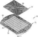
Фиг.1 - изометрическое изображение сверху с пространственным разделением деталей маркера дорожного покрытия в соответствии с первым вариантом осуществления настоящего изобретения.Figure 1 is an isometric top view with a spatial separation of the details of the pavement marker in accordance with the first embodiment of the present invention.
Фиг.2 - изометрическое изображение снизу с пространственным разделением деталей маркера дорожного покрытия, иллюстрируемого на фиг.1.Figure 2 is an isometric image from the bottom with a spatial separation of the details of the marker pavement illustrated in figure 1.
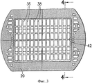
Фиг.3 - вид снизу основания маркера дорожного покрытия.Figure 3 is a bottom view of the base of the pavement marker.
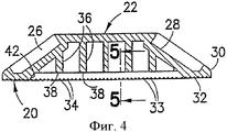
Фиг.4 - сечение, сделанное по линии 4-4, показанной на фиг.3.Figure 4 is a section taken along the line 4-4 shown in figure 3.
Фиг.5 - сечение, сделанное по линии 5-5, показанной на фиг.4.FIG. 5 is a sectional view taken along line 5-5 of FIG. 4.
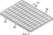
Фиг.6 - изометрическое изображение нижней крышки при обзоре сверху.6 is an isometric image of the bottom cover when viewed from above.
Фиг.7 - вид сверху нижней крышки.7 is a top view of the bottom cover.
Фиг.8 - сечение, сделанное по линии 8-8, показанной на фиг.7.Fig. 8 is a sectional view taken along line 8-8 of Fig. 7.
Фиг.9 - вид снизу собранного маркера дорожного покрытия.Fig.9 is a bottom view of the assembled pavement marker.
Фиг.10 - сечение, сделанное по линии 10-10, показанной на фиг.9.Figure 10 is a section taken along the line 10-10 shown in figure 9.
Фиг.11 - сечение, иллюстрирующее вставленное ребро в паз перед сваркой.11 is a cross section illustrating the inserted rib in the groove before welding.
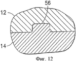
Фиг.12 - сечение, иллюстрирующее вставленное ребро в паз после сварки.12 is a section illustrating an inserted rib in a groove after welding.
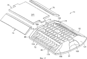
Фиг.13 - изометрическое изображение с пространственным разделением деталей альтернативного маркера дорожного покрытия в соответствии с настоящим изобретением.FIG. 13 is an exploded isometric view of an alternative pavement marker in accordance with the present invention. FIG.
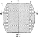
Фиг.14 - вид снизу маркера дорожного покрытия, иллюстрируемого на фиг.13.Fig. 14 is a bottom view of the pavement marker illustrated in Fig. 13.
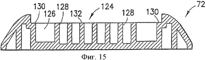
Фиг.15 - сечение, сделанное по линии 15-15, показанной на фиг.14.Fig. 15 is a sectional view taken along line 15-15 of Fig. 14.
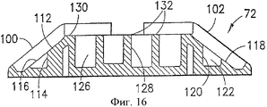
Фиг.16 - сечение, сделанное по линии 16-16, показанной на фиг.14.Fig. 16 is a sectional view taken along line 16-16 of Fig. 14.
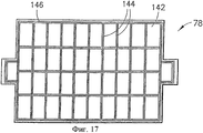
Фиг.17 - вид снизу верхней крышки.17 is a bottom view of the top cover.
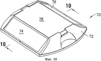
Фиг.18 - изометрическое изображение собранного маркера дорожного покрытия.Fig. 18 is an isometric view of an assembled pavement marker.
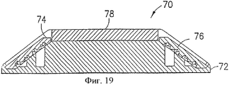
Фиг.19 - сечение, сделанное по линии 19-19, показанной на фиг.18.Fig.19 is a section taken along the line 19-19 shown in Fig.18.
ПОДРОБНОЕ ОПИСАНИЕ ПРЕДПОЧТИТЕЛЬНЫХ ВАРИАНТОВ ОСУЩЕСТВЛЕНИЯ НАСТОЯЩЕГО ИЗОБРЕТЕНИЯDETAILED DESCRIPTION OF THE PREFERRED EMBODIMENTS OF THE PRESENT INVENTION
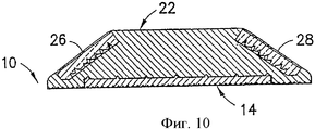
Маркер дорожного покрытия, соответствующий настоящему изобретению, на фиг.1-12, в общем, указан ссылочным номером 10. Маркер 10 дорожного покрытия содержит основание 12, нижнюю крышку 14 и переднюю и заднюю линзы 16 и 18 соответственно. Основание 12 получено унитарно литьем из термопластичного материала и имеет нижнюю часть 20, показанную лучше всего на фиг.2, и противоположную верхнюю часть 22, показанную лучше всего на фиг.1. Верхняя часть 22 образована с передним и задним приемными углублениями 26 и 28, предназначенными для приема (установки) линз 16 и 18 соответственно. Линзы 16 и 18 могут быть закреплены в соответствующих углублениях 26 и 28 для линз посредством клея или механических крепежных средств. Другие аспекты формы и функции верхней части 22 основания 12 и линз 16 и 18 не являются критическими для первого варианта осуществления настоящего изобретения и дополнительно не описываются в этой заявке. Однако конструкция и функция верхней поверхности маркера дорожного покрытия является более существенной для второго варианта осуществления настоящего изобретения и более подробно описывается ниже в контексте второго варианта осуществления.The pavement marker corresponding to the present invention, in FIGS. 1-12, is generally indicated by
Нижняя часть 20 основания 12 имеет внешнюю периферию 30, а периферийная область 32 проходит в направлении внутрь от внешней периферии 30. Периферийная область 32 отличается, по меньшей мере, одной матрицей пазов 33, отделенных друг от друга V-образными гребнями 34. Гребни 34 ограничивают пики, которые лежат по существу в одной плоскости. Матрица пазов 33 и гребней 34 по периферийной области увеличивает площадь поверхности нижней части 20 и, следовательно, улучшает способность битума или другого адгезива удерживать маркер 10 дорожного покрытия по существу в фиксированном положении на поверхности дорожного покрытия.The
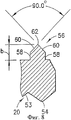
Нижняя часть 20 основания 12 дополнительно имеет множество колонковых отверстий 36, отстоящих в направлении внутрь от периферийной области 32 и отделенных друг от друга перегородками 38. Колонковые отверстия 36 предусмотрены для достижения по существу однородной толщины полимерного материала по основанию 12 для гарантии по существу однородных размеров полимерного материала после отверждения. Следовательно, перегородки 38 имеют по существу одинаковую толщину. Перегородки 38 имеют нижние торцы 40, которые ограничивают по существу общую плоскость, параллельную плоскости, ограниченной гребнями 34 на периферийной области 30. Однако плоскость, ограниченная нижними торцами 40 перегородок 38, смещена вверх относительно плоскости, ограниченной гребнями 34. Таким образом, нижняя часть 20 ограничивает углубление 42, которое охватывает колонковые отверстия 36 и перегородки 38. Нижний торец 40 каждой перегородки 38 отличается центральным пазом 44. Каждый паз 44 имеет, в общем, прямоугольное поперечное сечение и имеет верхнюю поверхность 46 и противоположные боковые поверхности 48. Эти боковые поверхности расходятся в направлении наружу и друг от друга на дополнительные расстояния от верхней поверхности для облегчения литья. Каждый паз предпочтительно имеет глубину "а", составляющую 0,01-0,03 дюйма (0,254-0,762 мм), а предпочтительнее всего - приблизительно 0,018 дюйма (0,457 мм). Пазы 44 также образованы для прохождения вокруг периметра углубления 42.The
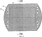
Нижняя крышка 14 является по существу планарной прямоугольной крышкой с внешней периферией, по существу соответствующей форме углубления 42 в нижней части 20 основания 12. Более конкретно, нижняя крышка 14 имеет нижнюю поверхность 50, как показано на фиг.2, и противоположную верхнюю поверхность 52, как показано на фиг.1, 6 и 7. Нижняя поверхность 50 образована с матрицей пазов 53, отделенных друг от друга гребнями 54. Пики гребней 54 ограничивают по существу общую плоскость. Комбинация пазов 53 и гребней 54 функционирует по существу для увеличения площади нижней поверхности 50 крышки 14 для увеличения удерживания нижней крышки 14 битумом или другим адгезивом, используемым для удерживания маркера 10 дорожного покрытия на поверхности дорожного покрытия.The
Верхняя поверхность 52 нижней крышки 14 отличается матрицей направляющих энергию ребер 56, которая расположена так, чтобы точно совпадать с перегородками 38 на нижней части 20 основания. Каждое ребро 56 имеет пару по существу параллельных боковых поверхностей 58 и пару сходящихся поверхностей 60, которые встречаются вдоль по существу линейного края 62. Расстояние между боковыми краями 58 каждого направляющего энергию ребра 56 меньше расстояния между боковыми краями 48 каждого паза 44. Однако высота "b" каждого ребра 56 составляет приблизительно 0,3-0,4 дюйма (7,62-10,2 мм), а предпочтительно - приблизительно 0,35 дюйма (8,9 мм). Более конкретно, высота "b" каждого ребра 56 превышает глубину соответствующих пазов 44. Конические поверхности 60 и край 62 между каждой парой конических поверхностей 60 ограничивают направляющие энергию устройства, как объясняется в этой заявке.The
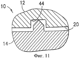
Маркер 10 дорожного покрытия собирают путем крепления линз 16 и 18 в углублениях 26 и 28 для линз, соответственно, при использовании известной технологии, например, посредством клея или механических крепежных средств. Верхняя поверхность 52 нижней крышки 14 затем вставляется в направлении вверх в углубление 42 в нижней части 20 основания 12, как показано на фиг.9-12. Как результат ребра 56 на верхней поверхности 52 вставляются в пазы 44, образованные в нижней части 20, как показано на фиг.11. Собранный маркер 10 дорожного покрытия затем подается к аппарату для ультразвуковой сварки. Более конкретно, аппарат для ультразвуковой сварки содержит консоль, предназначенную для совмещения по существу с направляющими энергию ребрами 56. После этого давление и ультразвуковую энергию прикладывают посредством консоли так, чтобы направитель энергии, ограниченный коническими поверхностями 60 и краем 62 на каждом ребре 56, плавился и сплавлялся унитарно или интегрально с полимерным материалом, окружающим соответствующие пазы 44, как показано на фиг.12. Боковые поверхности 48 каждого паза 44 функционируют для канализации и вмещения расплавленного полимерного материала соответствующего ребра 56. Как результат обеспечивается меньшее распространение расплавленного полимерного материала и более эффективное удерживание нижней крышки 14 в углублении 42 основания 14.The
Альтернативный вариант осуществления маркера дорожного покрытия, иллюстрируемый на фиг.13-19, указан, в общем, ссылочным номером 70. Маркер 70 дорожного покрытия содержит основание 72, переднюю и заднюю линзы 74 и 76 соответственно и верхнюю крышку 78.An alternative embodiment of the pavement marker illustrated in FIGS. 13-19 is indicated generally by 70. The
Основание 72 унитарно отлито из жесткого полимерного материала и содержит противоположные передний и задний края 80 и 82 соответственно и противоположные первый и второй боковые края 84 и 86 соответственно. Основание 72 дополнительно содержит нижнюю часть 88, отличающуюся множеством матриц пазов 90 и V-образных гребней 92. Пазы 90 и гребни 92 функционируют для увеличения площади поверхности нижней части 88 основания 72. Не все пазы 90 и гребни 92 параллельны друг другу. В иллюстрируемом варианте осуществления нижняя часть 88 разделена на четыре квадранта. Пазы 90 и гребни 92 в каждом квадранте параллельны друг другу, но по существу перпендикулярны пазам 90 и гребням 92 в смежном ему квадранте. Таким образом, невероятно, чтобы маркер 70 дорожного покрытия скользил в поперечном направлении в битуме или другом адгезиве под действием сил, прикладываемых к маркеру 70 дорожного покрытия посредством удара шин транспортных средств.The
Нижняя часть 88 основания 72 имеет множество колонковых отверстий 94, но число их намного меньше, чем в нижней части 20 основания 12 первого варианта осуществления. Помимо всего прочего, в нижней части 88 основания 72 отсутствует углубление. Следовательно, маркер 70 дорожного покрытия не требует нижней крышки, описанной и иллюстрированной выше со ссылкой на первый вариант осуществления настоящего изобретения.The
Основание 72 дополнительно содержит верхнюю область, которая существенно отличается от верхней части основания 12, иллюстрируемого со ссылкой на первый вариант осуществления. Более конкретно, основание 72 имеет переднюю поверхность 100, которая имеет наклон вверх и внутрь от переднего края 80, и заднюю поверхности 102, которая имеет наклон вверх и назад от заднего края 82. Первая и вторая боковые поверхности 104 и 106 изогнуты вверх и вперед от соответствующих первого и второго боковых краев 84 и 86 и проходят между передней и задней поверхностями 100 и 102. Боковые поверхности 104 и 106 отличаются вогнутыми захватами 108 и 110 для пальцев соответственно для облегчения манипулирования и размещения маркера 70 дорожного покрытия.The base 72 further comprises an upper region, which is significantly different from the upper part of the
Передняя поверхность 100 отличается передним углублением 112 для линзы с множеством проходящих вниз передних колонковых отверстий 114, отделенных друг от друга множеством передних перегородок 116, как показано на фиг.13 и 16. Передние перегородки 116 имеют верхние края, которые лежат по существу в общей плоскости. Переднее углубление 112 для линзы имеет размеры и конфигурацию для плотной установки передней линзы 74 так, чтобы части передней линзы 74, обращенные в направлении наружу, были по существу заподлицо с частями передней поверхности 100, смежной переднему углублению 112 для линзы. Передняя линза 74 может быть закреплена в переднем углублении 112 для линзы посредством клея или механических крепежных средств. Ввиду такого крепления колонковые отверстия 114 в переднем углублении 112 для линзы покрыты передней линзой 74.The
Задняя поверхность 102 образована для содержания заднего углубления 118 для линзы с множеством задних колонковых отверстий 120, отделенных друг от друга множеством задних перегородок 122, как показано на фиг.13 и фиг.16. Задние перегородки 122 имеют верхние торцы 122, которые лежат в общей плоскости. Задние углубления для линзы имеют размер для установки задней линзы 76 так, чтобы верхняя и внешняя поверхность задней линзы 76 была по существу заподлицо с частями задней поверхности 102, смежной заднему углублению 118 для линзы. Задняя линза 76 может быть закреплена в заднем углублении 118 для линзы подобным образом, что и крепление передней линзы 74 в заднем углублении 112 для линзы.The
Основание 72 дополнительно содержит верхнее углубление 124 для крышки, которое проходит в направлении от передней стороны к задней стороне между передним углублением 112 для линзы и задним углублением 118 для линзы, как показано на фиг.13 и фиг.15. Помимо всего прочего, верхнее углубление 124 для крышки проходит в боковом направлении между первой и второй боковыми поверхностями 104 и 106. Области основания 72, соответствующие верхнему углублению 124 для крышки, включают в себя множество проходящих в направлении вниз колонковых отверстий 126, отделенных друг от друга унитарной матрицей перегородок 128. Помимо всего прочего, колонковые отверстия 128 отстоят внутрь периферийными выступами 130, которые проходят вокруг всего периметра верхнего углубления 124 для крышки. Перегородки 128 и периферийные выступы 130 имеют верхние торцы 132, которые лежат по существу в общей плоскости, параллельной нижней части 88 основания 72. Углубление 124 для крышки предназначено для установки верхней крышки 78, как объясняется в этой заявке.The base 72 further comprises an
Каждая перегородка 128 имеет обращенный вверх паз 134 перегородки. Помимо всего прочего, периферийные выступы 130 имеют непрерывный периферийный паз 136, проходящий полностью вокруг верхнего углубления 124 для крышки. Пазы 134 и 136 имеют по существу идентичную форму поперечного сечения и по существу идентичны форме поперечного сечения пазов 44 в углублении 32 основания 12, описанных со ссылкой на первый вариант осуществления настоящего изобретения. Более конкретно, каждый паз 134 и 136 имеет существенно расширяющееся прямоугольное поперечное сечение с нижней поверхностью и боковыми поверхностями, которые немного расходятся в направлении друг от друга. Каждый паз 134 и 136 имеет по существу одну глубину, что и пазы 44, описанные со ссылкой на первый вариант осуществления настоящего изобретения.Each
Верхняя крышка 78 образована унитарно из люминесцентного полимерного материала, например поликарбоната, продаваемого компанией General Electric под торговым названием LEXAN®. Верхняя крышка 78 имеет по существу планарную верхнюю поверхность 140, как показано на фиг.13, и противоположную нижнюю поверхность 142, как показано на фиг.17. Нижняя поверхность 142 отличается матрицей проходящих в направлении вниз направляющих энергию ребер 144, которые имеют размер и конструкцию для вставления в пазы 134 в перегородках 128, образованных в основании 72. Помимо всего прочего, нижняя поверхность 142 верхней крышки 78 имеет непрерывное периферийное направляющее энергию ребро 146, проходящее полностью вокруг периферии нижней поверхности 142 верхней крышки 78 для вставления в периферийный паз 136. Направляющие энергию ребра 144 и 146 имеют формы и размеры поперечного сечения, существенно согласующиеся с формами и размерами поперечного сечения направляющих энергию ребер 56, образованных на нижней крышке 14 первого варианта осуществления настоящего изобретения.
Маркер 70 дорожного покрытия собирают путем крепления передней и задней линз 74 и 76 в переднем и заднем углублениях 112 и 118 для линзы с помощью стандартных средств крепления, например посредством склеивания, сварки или механических крепежных средств. После этого верхнюю крышку 78 вставляют в верхнее углубление 124 для крышки. Как результат, направляющие энергию ребра 144 свободно вставляются в пазы 134 перегородок. Одновременно с этим периферийные направляющие энергию ребра 146 вставляются в периферийный паз 136 непрерывно вокруг периферии верхней крышки 78. Затем собранный маркер 70 для дорожного покрытия подают к аппарату для ультразвуковой сварки. Аппарат имеет консоль, которая по существу точно совмещается с направляющими энергию ребрами 144 и 146. После этого к верхней крышке 78 прикладывают механическое давление и звуковую энергию. Как результат полимерный материал направляющих энергию ребер 144 и 146 плавится и заполняет соответствующие пазы 134 и 136. В соответствии с этим между направляющими энергию ребрами 144 и 146 и частями основания 72, смежными пазам 134 и 136, обеспечивается получение интегрального или унитарного соединения. Эта сварная область ограничивает герметичный шов, непрерывно проходящий по периферии верхней крышки 78 для предотвращения затекания влаги в колонковые отверстия 126 в основании 72. Такая влага может отрицательно повлиять на оптические характеристики и краевое свечение люминесцентного материала, из которого образована верхняя крышка 78. То, что направляющие энергию ребра 144 и 146 вставлены в пазы 132 и 134, уменьшает распространение расплавленного материала и канализирует расплавленный материал в небольшой поперечной области. Как результат будет существенно уменьшаться любое отрицательное влияние ультразвуковой сварки на оптические характеристики люминесцентного материала, из которого образована верхняя крышка 78.The
Хотя настоящее изобретение было описано со ссылкой на некоторые предпочтительные варианты осуществления, очевидно, что без отклонения от объема настоящего изобретения, ограниченного прилагаемой формулой изобретения, могут быть сделаны различные изменения. Например, взаимное контактное взаимодействие пазов с направителями энергии может быть приложено к углублениям для линз и линзам либо в первом, либо во втором варианте осуществления настоящего изобретения. Помимо всего прочего, могут быть предусмотрены другие рельефы пазов и направителей энергии и другие конфигурации пазов и направителей энергии.Although the present invention has been described with reference to some preferred embodiments, it is apparent that various changes can be made without departing from the scope of the present invention limited by the appended claims. For example, the mutual contact interaction of the grooves with the energy directors can be applied to the recesses for the lenses and lenses in either the first or second embodiment of the present invention. Among other things, other reliefs of the grooves and energy guides and other configurations of the grooves and energy guides may be provided.
Claims (11)
Приоритет: 09.06.2003. 11. A method of obtaining a pavement marker, providing for the formation of a base (72) with a lower surface (88) for placement on a pavement and an opposite upper surface, and the formation of a base (72) limits the recess (124) in the upper surface, core holes (126) extending into the upper recess (124) and separated from each other by partitions (128), forming a cover (78) to cover the core holes (126) in the base (72), positioning the cover (78) on the base (72) so that the cover (78) entered the recesses e (124) in the upper surface of the base (72), the application of ultrasonic energy to the specified cover (78) for welding the cover (78) to the partitions (128), in which the stage of formation of the base (72) involves the formation of a peripheral protrusion (130) around the perimeter recesses (124), the formation of grooves (134) in the partitions (128) and the peripheral groove (136) extending along the peripheral protrusion (130), the step of forming the cover (78) provides for the formation of the cover (78) from a material for generating an optical signal having energy guiding ribs (144) for insertion into the grooves (134, 136), and the step of applying ultrasonic energy is performed to hermetically seal the cover (78) in the recess (124) and, essentially, to drain and hold the molten material of the energy-guiding ribs (144) in the grooves (134, 136) to significantly reduce the negative effect of ultrasonic welding on the optical characteristics of the cap (78).
Priority: 06/09/2003.
Applications Claiming Priority (2)
| Application Number | Priority Date | Filing Date | Title |
|---|---|---|---|
| US10/458,533 US6851888B2 (en) | 2003-06-09 | 2003-06-09 | Pavement marker |
| US10/458,533 | 2003-06-09 |
Publications (2)
| Publication Number | Publication Date |
|---|---|
| RU2005136012A RU2005136012A (en) | 2006-07-10 |
| RU2365701C2 true RU2365701C2 (en) | 2009-08-27 |
Family
ID=33490442
Family Applications (1)
| Application Number | Title | Priority Date | Filing Date |
|---|---|---|---|
| RU2005136012/03A RU2365701C2 (en) | 2003-06-09 | 2004-05-25 | Road carpet marker |
Country Status (12)
| Country | Link |
|---|---|
| US (1) | US6851888B2 (en) |
| EP (1) | EP1641979B1 (en) |
| KR (1) | KR101194929B1 (en) |
| CN (2) | CN1802473A (en) |
| AU (2) | AU2004248115B2 (en) |
| BR (1) | BRPI0411384A (en) |
| CA (1) | CA2527279C (en) |
| ES (1) | ES2436607T3 (en) |
| HK (1) | HK1124097A1 (en) |
| MX (1) | MXPA05013231A (en) |
| RU (1) | RU2365701C2 (en) |
| WO (1) | WO2004111343A2 (en) |
Families Citing this family (6)
| Publication number | Priority date | Publication date | Assignee | Title |
|---|---|---|---|---|
| DE102008033438A1 (en) * | 2007-07-18 | 2009-04-09 | Denso Corporation, Kariya | Air passage opening and closing device |
| US20110164922A1 (en) * | 2010-01-05 | 2011-07-07 | David Michael Moxlow | Roadway marker and reflector guard |
| WO2011133789A2 (en) * | 2010-04-21 | 2011-10-27 | Teknotraffic, Inc. | Road marker with solid body and lens protection |
| US20130170906A1 (en) * | 2012-01-03 | 2013-07-04 | Hung-Chen Lee | Reflective roadstud and manufacture of the same |
| US8734047B2 (en) * | 2012-01-09 | 2014-05-27 | Robert K. Hughes, Jr. | Traffic control marker with mesh base |
| US20170002526A1 (en) * | 2014-01-21 | 2017-01-05 | Ignácio HERNÁNDEZ SANTACRUZ | Reflectors |
Family Cites Families (11)
| Publication number | Priority date | Publication date | Assignee | Title |
|---|---|---|---|---|
| US442336A (en) | 1890-12-09 | Carbon electrode and method of making the same | ||
| US3179009A (en) * | 1962-09-18 | 1965-04-20 | Koch & Sous H | Lane reflector having plural reflecting surfaces |
| US4694627A (en) * | 1985-05-28 | 1987-09-22 | Omholt Ray | Resiliently-cushioned adhesively-applied floor system and method of making the same |
| US4875798A (en) * | 1988-06-30 | 1989-10-24 | Minnesota Mining And Manufacturing Company | Retroreflective pavement marker |
| US5340231A (en) * | 1991-12-10 | 1994-08-23 | Stimsonite Corporation | Pavement marker |
| MX9708693A (en) * | 1995-05-19 | 1998-02-28 | Minnesota Mining & Mfg | Raised retroreflective pavement marker. |
| US5667334A (en) * | 1995-06-13 | 1997-09-16 | Stimsonite Corporation | Base for roadway marker |
| US6334734B1 (en) * | 1999-08-30 | 2002-01-01 | Adil Attar | One piece reflective pavement marker and method of making |
| US6267530B1 (en) * | 1999-10-16 | 2001-07-31 | Adil Attar | Reflective pavement marker |
| DE19950512B4 (en) * | 1999-10-20 | 2004-02-26 | Stiebel Eltron Gmbh & Co. Kg | Assembly connectable by ultrasonic welding |
| US6579036B2 (en) * | 2001-06-22 | 2003-06-17 | Adil Attar | Reflective pavement marker and method of making |
-
2003
- 2003-06-09 US US10/458,533 patent/US6851888B2/en not_active Expired - Lifetime
-
2004
- 2004-05-25 RU RU2005136012/03A patent/RU2365701C2/en not_active IP Right Cessation
- 2004-05-25 CN CNA2004800158819A patent/CN1802473A/en active Pending
- 2004-05-25 ES ES04753298.1T patent/ES2436607T3/en active Active
- 2004-05-25 AU AU2004248115A patent/AU2004248115B2/en active Active
- 2004-05-25 MX MXPA05013231A patent/MXPA05013231A/en active IP Right Grant
- 2004-05-25 WO PCT/US2004/016443 patent/WO2004111343A2/en active Search and Examination
- 2004-05-25 CN CN2008100854482A patent/CN101265692B/en active Active
- 2004-05-25 EP EP04753298.1A patent/EP1641979B1/en active Active
- 2004-05-25 BR BRPI0411384-5A patent/BRPI0411384A/en not_active IP Right Cessation
- 2004-05-25 KR KR1020057023496A patent/KR101194929B1/en active IP Right Grant
- 2004-05-25 CA CA002527279A patent/CA2527279C/en active Active
-
2008
- 2008-12-09 HK HK08113381.2A patent/HK1124097A1/en unknown
-
2009
- 2009-04-23 AU AU2009201630A patent/AU2009201630B2/en active Active
Also Published As
| Publication number | Publication date |
|---|---|
| KR20060025164A (en) | 2006-03-20 |
| US6851888B2 (en) | 2005-02-08 |
| AU2004248115A1 (en) | 2004-12-23 |
| MXPA05013231A (en) | 2006-03-09 |
| AU2009201630B2 (en) | 2010-11-11 |
| ES2436607T3 (en) | 2014-01-03 |
| BRPI0411384A (en) | 2006-07-18 |
| HK1124097A1 (en) | 2009-07-03 |
| AU2009201630A1 (en) | 2009-05-21 |
| CA2527279A1 (en) | 2004-12-23 |
| US20040247387A1 (en) | 2004-12-09 |
| RU2005136012A (en) | 2006-07-10 |
| WO2004111343A2 (en) | 2004-12-23 |
| CN101265692A (en) | 2008-09-17 |
| CN1802473A (en) | 2006-07-12 |
| WO2004111343A3 (en) | 2005-02-10 |
| AU2004248115B2 (en) | 2009-01-29 |
| EP1641979A2 (en) | 2006-04-05 |
| CN101265692B (en) | 2012-05-30 |
| KR101194929B1 (en) | 2012-10-25 |
| EP1641979B1 (en) | 2013-10-23 |
| CA2527279C (en) | 2008-11-18 |
Similar Documents
| Publication | Publication Date | Title |
|---|---|---|
| KR100506557B1 (en) | Raised Retroreflective Pavement Marker | |
| AU2009201630B2 (en) | Pavement marker | |
| US6066216A (en) | Mesa forming weld depth limitation feature for use with energy director in ultrasonic welding | |
| CN1289773C (en) | Concrete placing form | |
| CN1088171C (en) | Vehicle lamp and vibration type welding method for vehicle lamp | |
| JP6006822B2 (en) | Resin member | |
| GB2325638A (en) | Fusion-welding leg in a vehicle lamp | |
| RU2382845C2 (en) | Marker of road carpet with amplified signal of daytime | |
| KR20160016348A (en) | Laser welding structure | |
| CN1269260C (en) | Sealing-up structure of insulate line | |
| CA1129946A (en) | Method for the manufacture of an electrochemical cell or battery | |
| JP3702090B2 (en) | Electrical equipment case | |
| US5092643A (en) | Automobile bumper | |
| JPH09300471A (en) | Method for bonding plastics and bonded structure | |
| JP2000135740A (en) | Case for electric machinery and its production | |
| JPH08132529A (en) | Resin product, production thereof and resin member | |
| JPH02254013A (en) | Manufacture of vehicle window | |
| GB2424472A (en) | Seal between a lens and a reflector on a vehicle | |
| KR100660660B1 (en) | Semiconductor device | |
| KR101917768B1 (en) | Heterojunction body | |
| CN215663282U (en) | Outer decorative plate structure of stand and vehicle | |
| KR20170120845A (en) | Composite of different materials | |
| KR102033219B1 (en) | Fixing member of waterproof member | |
| JP2018176443A (en) | Method for manufacturing resin bonded body, and resin bonded body | |
| JPH10302512A (en) | Lighting system for vehicle |
Legal Events
| Date | Code | Title | Description |
|---|---|---|---|
| MM4A | The patent is invalid due to non-payment of fees |
Effective date: 20140526 |