KR20170120845A - Composite of different materials - Google Patents
Composite of different materials Download PDFInfo
- Publication number
- KR20170120845A KR20170120845A KR1020160049240A KR20160049240A KR20170120845A KR 20170120845 A KR20170120845 A KR 20170120845A KR 1020160049240 A KR1020160049240 A KR 1020160049240A KR 20160049240 A KR20160049240 A KR 20160049240A KR 20170120845 A KR20170120845 A KR 20170120845A
- Authority
- KR
- South Korea
- Prior art keywords
- engaging portion
- adhesive
- steel
- present
- composite
- Prior art date
Links
Images


Classifications
-
- B—PERFORMING OPERATIONS; TRANSPORTING
- B32—LAYERED PRODUCTS
- B32B—LAYERED PRODUCTS, i.e. PRODUCTS BUILT-UP OF STRATA OF FLAT OR NON-FLAT, e.g. CELLULAR OR HONEYCOMB, FORM
- B32B7/00—Layered products characterised by the relation between layers; Layered products characterised by the relative orientation of features between layers, or by the relative values of a measurable parameter between layers, i.e. products comprising layers having different physical, chemical or physicochemical properties; Layered products characterised by the interconnection of layers
- B32B7/04—Interconnection of layers
-
- B—PERFORMING OPERATIONS; TRANSPORTING
- B23—MACHINE TOOLS; METAL-WORKING NOT OTHERWISE PROVIDED FOR
- B23K—SOLDERING OR UNSOLDERING; WELDING; CLADDING OR PLATING BY SOLDERING OR WELDING; CUTTING BY APPLYING HEAT LOCALLY, e.g. FLAME CUTTING; WORKING BY LASER BEAM
- B23K11/00—Resistance welding; Severing by resistance heating
- B23K11/10—Spot welding; Stitch welding
- B23K11/11—Spot welding
- B23K11/115—Spot welding by means of two electrodes placed opposite one another on both sides of the welded parts
-
- B—PERFORMING OPERATIONS; TRANSPORTING
- B23—MACHINE TOOLS; METAL-WORKING NOT OTHERWISE PROVIDED FOR
- B23K—SOLDERING OR UNSOLDERING; WELDING; CLADDING OR PLATING BY SOLDERING OR WELDING; CUTTING BY APPLYING HEAT LOCALLY, e.g. FLAME CUTTING; WORKING BY LASER BEAM
- B23K11/00—Resistance welding; Severing by resistance heating
- B23K11/16—Resistance welding; Severing by resistance heating taking account of the properties of the material to be welded
- B23K11/20—Resistance welding; Severing by resistance heating taking account of the properties of the material to be welded of different metals
-
- B—PERFORMING OPERATIONS; TRANSPORTING
- B32—LAYERED PRODUCTS
- B32B—LAYERED PRODUCTS, i.e. PRODUCTS BUILT-UP OF STRATA OF FLAT OR NON-FLAT, e.g. CELLULAR OR HONEYCOMB, FORM
- B32B7/00—Layered products characterised by the relation between layers; Layered products characterised by the relative orientation of features between layers, or by the relative values of a measurable parameter between layers, i.e. products comprising layers having different physical, chemical or physicochemical properties; Layered products characterised by the interconnection of layers
- B32B7/04—Interconnection of layers
- B32B7/08—Interconnection of layers by mechanical means
-
- B—PERFORMING OPERATIONS; TRANSPORTING
- B32—LAYERED PRODUCTS
- B32B—LAYERED PRODUCTS, i.e. PRODUCTS BUILT-UP OF STRATA OF FLAT OR NON-FLAT, e.g. CELLULAR OR HONEYCOMB, FORM
- B32B7/00—Layered products characterised by the relation between layers; Layered products characterised by the relative orientation of features between layers, or by the relative values of a measurable parameter between layers, i.e. products comprising layers having different physical, chemical or physicochemical properties; Layered products characterised by the interconnection of layers
- B32B7/04—Interconnection of layers
- B32B7/12—Interconnection of layers using interposed adhesives or interposed materials with bonding properties
-
- B—PERFORMING OPERATIONS; TRANSPORTING
- B23—MACHINE TOOLS; METAL-WORKING NOT OTHERWISE PROVIDED FOR
- B23K—SOLDERING OR UNSOLDERING; WELDING; CLADDING OR PLATING BY SOLDERING OR WELDING; CUTTING BY APPLYING HEAT LOCALLY, e.g. FLAME CUTTING; WORKING BY LASER BEAM
- B23K2101/00—Articles made by soldering, welding or cutting
- B23K2101/18—Sheet panels
-
- B—PERFORMING OPERATIONS; TRANSPORTING
- B23—MACHINE TOOLS; METAL-WORKING NOT OTHERWISE PROVIDED FOR
- B23K—SOLDERING OR UNSOLDERING; WELDING; CLADDING OR PLATING BY SOLDERING OR WELDING; CUTTING BY APPLYING HEAT LOCALLY, e.g. FLAME CUTTING; WORKING BY LASER BEAM
- B23K2103/00—Materials to be soldered, welded or cut
- B23K2103/18—Dissimilar materials
-
- B23K2201/18—
-
- B23K2203/18—
Abstract
Description
본 발명은 이종소재를 포함하는 복합체 및 그 제조방법에 관한 것으로, 보다 상세하게는 스틸재질을 용접하는 기존의 용접라인을 이용하여 이종소재를 결합할 수 있는 이종소재를 포함하는 복합체 및 그 제조방법에 관한 것이다.
The present invention relates to a composite material containing different materials and a manufacturing method thereof, and more particularly, to a composite material containing a heterogeneous material capable of bonding a different material by using a conventional welding line for welding steel material, .
일반적으로, 자동차에 사용되는 판재는 스틸을 포함한 단일 재질로 제작하는 경우가 일반적이나, 소재의 경량화와 연비 절감을 위해 이종소재를 포함한 복합체가 많이 사용되고 있다.Generally, plate materials used in automobiles are generally made of a single material including steel, but a composite material containing different materials is widely used to reduce the weight of the material and reduce fuel consumption.
종래에는 스틸 형상의 판재를 적층한 상태에서, 스폿용접 장치를 이용하여 적층된 스틸재질의 판재를 서로 고정시키는 작업을 수행한다. 소재를 경량화하기 위하여 스틸재질의 판재와 비철금속의 판재를 서로 접합시켜 사용하는 복합체가 제안되었으나, 기존의 스틸판재 용접에 사용되는 용접라인을 사용하지 못하고 새로운 생산라인을 설치해야 하므로 생산비용이 상승하는 문제점이 있다. 따라서 이를 개선할 필요성이 요청된다. Conventionally, an operation of fixing the laminated steel material plates to each other by using a spot welding apparatus in a state where the steel-like plate materials are laminated is performed. In order to reduce the weight of the material, a composite material in which a steel plate and a non-ferrous plate are bonded to each other has been proposed. However, since a new production line must be installed without using a welding line used for welding a steel plate, There is a problem. Therefore, there is a need for improvement.
본 발명의 배경기술은 대한민국 특허등록번호 제1283200호(2013.07.01 공개, 발명의 명칭: 이종 소재로 이루어진 복합체 및 그 제조방법)에 게시되어 있다.
BACKGROUND ART [0002] The background art of the present invention is disclosed in Korean Patent Registration No. 1283200 (published on Jul. 31, 201, entitled "
본 발명은 상기와 같은 문제점을 개선하기 위해 창출된 것으로, 본 발명의 목적은 스틸재질을 용접하는 기존의 용접라인을 이용하여 이종소재를 결합할 수 있는 이종소재를 포함하는 복합체 및 그 제조방법을 제공하는 것이다.
It is an object of the present invention to provide a composite material including a heterogeneous material capable of bonding a different material by using a conventional welding line for welding steel materials and a method of manufacturing the same. .
본 발명에 따른 이종소재를 포함하는 복합체는: 판 형상의 제1부재와, 제1부재와 마주하며 제1부재에 겹쳐지는 형상으로 설치되며 제1부재의 재질과 다른 재질로 이루어진 제2부재 및 제2부재를 관통하여 제1부재를 향한 방향으로 돌출되며 제1부재와 같은 재질로 성형되는 결합부를 포함하는 것을 특징으로 한다.A composite comprising a heterogeneous material according to the present invention comprises: a first member in the form of a plate; a second member provided in a shape that overlaps with the first member and overlapped with the first member, And an engaging portion that protrudes in a direction toward the first member through the second member and is molded from the same material as the first member.
또한 제1부재와 결합부는 스틸을 재질로 하며, 제2부재는 비철금속을 재질로 하는 것이 바람직하다.It is preferable that the first member and the engaging portion are made of steel and the second member is made of a non-ferrous metal.
또한 본 발명은, 제2부재와 결합부의 사이에 도포되어 제2부재에 결합부를 고정시키는 제1접착부재를 더 포함하는 것이 바람직하다.Further, it is preferable that the present invention further includes a first adhesive member which is applied between the second member and the engaging portion to fix the engaging portion to the second member.
또한 결합부는, 제2부재의 일측면에 도포된 제1접착부재와 마주하는 형상으로 설치되며 제2부재의 외측에 적층되는 걸림부재 및 걸림부재에서 연장되어 제2부재를 관통하며 제1부재를 향한 방향으로 돌출되는 고정돌기를 포함하는 것이 바람직하다.The engaging portion is provided in a shape facing the first adhesive member coated on one side face of the second member and is extended from the engaging member which is stacked on the outer side of the second member and passes through the second member, And a fixing protrusion protruding in a direction toward the fixing member.
또한 본 발명은, 접착성분을 포함하며 제1부재와 제2부재의 사이에 적층되며, 서로 마주하는 제1부재와 제2부재에 접착되는 제2접착부재를 더 포함하는 것이 바람직하다.It is also preferable that the present invention further comprises a first member including an adhesive component and stacked between the first member and the second member, and a second adhesive member adhered to the second member.
본 발명에 따른 이종소재를 포함하는 복합체의 제조방법은: 제1부재의 상측에 제1부재와 다른 재질로 이루어진 제2부재를 적층하는 단계와, 제1부재와 같은 재질로 이루어지며 일측은 제2부재의 외측에 위치하며 타측은 제2부재를 관통하여 제1부재를 향한 방향으로 돌출되는 결합부를 제2부재에 가조립하는 단계 및 결합부를 스폿용접하여 제1부재와 제2부재를 고정시키는 단계를 포함하는 것을 특징으로 한다.A method of manufacturing a composite material including a heterogeneous material according to the present invention comprises the steps of: stacking a first member and a second member different from the first member on an upper side of the first member; Fixing the first member and the second member by spot-welding the engaging portion to the second member, the engaging portion protruding in the direction toward the first member through the second member, the other side being located outside the two members, And a control unit.
또한 제1부재와 결합부는 스틸을 재질로 하며, 제2부재는 비철금속을 재질로 하는 것이 바람직하다.It is preferable that the first member and the engaging portion are made of steel and the second member is made of a non-ferrous metal.
또한 결합부를 제2부재에 가조립하는 단계에서, 결합부와 제2부재의 사이에 제1접착부재가 설치되는 것이 바람직하다.
It is also preferable that a first adhesive member is provided between the engaging portion and the second member in the step of assembling the engaging portion to the second member.
본 발명에 따른 이종소재를 포함하는 복합체 및 그 제조방법은, 스틸재질로 이루어진 결합부가 비철금속 재질의 제2부재를 관통하여 스틸재질로 이루어진 제1부재에 용접되므로, 스틸재질을 용접하는 기존의 용접라인을 이용할 수 있어서 생산비를 절감할 수 있다.
The composite material including the different materials and the method of manufacturing the same according to the present invention is characterized in that the composite material made of steel is welded to the first member made of steel through the second member made of nonferrous metal, Lines can be used to reduce production costs.
도 1은 본 발명의 일 실시예에 따른 이종소재를 포함하는 복합체가 제1전극과 제2전극의 사이에 위치된 상태를 개략적으로 도시한 단면도이다.
도 2는 본 발명의 일 실시예에 따른 제1부재와 제2부재를 도시한 단면도이다.
도 3은 본 발명의 일 실시예에 따른 제2부재에 결합부가 설치된 상태를 도시한 단면도이다.
도 4는 본 발명의 일 실시예에 따른 결합부가 스폿용접기의 동작으로 제1부재에 결합되는 상태를 도시한 단면도이다.
도 5는 본 발명의 일 실시예에 따른 제1부재와 제2부재의 사이에 제2접착부재가 추가로 설치된 상태를 도시한 단면도이다.
도 6은 본 발명의 일 실시예에 따른 결합부를 도시한 사시도이다.
도 7은 본 발명의 일 실시예에 따른 결합부를 도시한 정면도이다.
도 8은 본 발명의 일 실시예에 따른 이종소재를 포함하는 복합체의 제조방법을 도시한 순서도이다.FIG. 1 is a cross-sectional view schematically illustrating a state where a composite material containing a heterogeneous material is positioned between a first electrode and a second electrode according to an embodiment of the present invention. Referring to FIG.
2 is a cross-sectional view illustrating a first member and a second member according to an embodiment of the present invention.
3 is a cross-sectional view illustrating a state in which a coupling unit is installed on a second member according to an embodiment of the present invention.
FIG. 4 is a cross-sectional view illustrating a state where a coupling portion according to an embodiment of the present invention is coupled to a first member by operation of a spot welder.
5 is a cross-sectional view showing a state in which a second adhesive member is additionally provided between the first member and the second member according to the embodiment of the present invention.
6 is a perspective view illustrating a coupling unit according to an embodiment of the present invention.
7 is a front view showing a coupling unit according to an embodiment of the present invention.
FIG. 8 is a flowchart illustrating a method of manufacturing a composite material including a heterogeneous material according to an embodiment of the present invention.
이하 첨부된 도면들을 참조하여 본 발명의 일 실시예에 따른 이종소재를 포함하는 복합체 및 그 제조방법을 설명한다. 이 과정에서 도면에 도시된 선들의 두께나 구성요소의 크기 등은 설명의 명료성과 편의상 과장되게 도시되어 있을 수 있다.DETAILED DESCRIPTION OF THE PREFERRED EMBODIMENTS The present invention will now be described more fully with reference to the accompanying drawings, in which exemplary embodiments of the invention are shown. In this process, the thicknesses of the lines and the sizes of the components shown in the drawings may be exaggerated for clarity and convenience of explanation.
또한 후술되는 용어들은 본 발명에서의 기능을 고려하여 정의된 용어들로서, 이는 사용자, 운용자의 의도 또는 관례에 따라 달라질 수 있다. 그러므로 이러한 용어들에 대한 정의는 본 명세서 전반에 걸친 내용을 토대로 내려져야 할 것이다.
Further, the terms described below are defined in consideration of the functions of the present invention, which may vary depending on the intention or custom of the user, the operator. Therefore, definitions of these terms should be made based on the contents throughout this specification.
도 1은 본 발명의 일 실시예에 따른 이종소재를 포함하는 복합체가 제1전극과 제2전극의 사이에 위치된 상태를 개략적으로 도시한 단면도이며, 도 2는 본 발명의 일 실시예에 따른 제1부재와 제2부재를 도시한 단면도이며, 도 3은 본 발명의 일 실시예에 따른 제2부재에 결합부가 설치된 상태를 도시한 단면도이며, 도 4는 본 발명의 일 실시예에 따른 결합부가 스폿용접기의 동작으로 제1부재에 결합되는 상태를 도시한 단면도이다.FIG. 1 is a cross-sectional view schematically illustrating a state where a composite material containing a different material is disposed between a first electrode and a second electrode according to an embodiment of the present invention. FIG. 2 is a cross- FIG. 3 is a cross-sectional view illustrating a state where a coupling unit is attached to a second member according to an embodiment of the present invention, and FIG. 4 is a cross-sectional view illustrating a coupling according to an embodiment of the present invention. And joined to the first member by the operation of the additional spot welder.
도 1 내지 도 4에 도시된 바와 같이, 본 발명의 일 실시예에 따른 이종소재를 포함하는 복합체(1)는, 판 형상의 제1부재(10)와, 제1부재(10)와 마주하며 제1부재(10)에 겹쳐지는 형상으로 설치되며 제1부재(10)의 재질과 다른 재질로 이루어진 제2부재(20) 및 제2부재(20)를 관통하여 제1부재(10)를 향한 방향으로 돌출되며 제1부재(10)와 같은 재질로 성형되는 결합부(30)를 포함한다.1 to 4, a composite 1 including a different material according to an embodiment of the present invention includes a plate-shaped
제1부재(10)는 판 형상으로 이루어지며 수평방향으로 배치된다. 일 실시예에 따른 제1부재(10)는 스틸(STEEL)을 재질로 한다.The
제2부재(20)는 제1부재(10)와 마주하며 제1부재(10)에 겹쳐지는 형상으로 설치되며, 제1부재(10)의 재질과 다른 재질로 이루어진다. 제2부재(20)도 제1부재(10)와 같이 판 형상으로 형성되며 수평방향으로 배치된다.The
일 실시예에 따른 제1부재(10)와 결합부(30)는 스틸을 재질로 하며, 제2부재(20)는 비철금속을 재질로 한다. 제1부재(10)와 제2부재(20)는 생산라인에서 지그에 의해 제품간 이동이 구속된 상태에서 결합부(30)의 용접작업이 이루어진다.The
제2부재(20)에는 결합부(30)가 설치되기 위한 통공홀부(22)가 단수 또는 복수로 구비된다. 결합부(30)는 제2부재(20)의 통공홀부(22)를 통해 제1부재(10)를 향한 방향으로 이동되어 제1부재(10)에 접한 상태로 용접된다.The second member (20) is provided with a single or a plurality of through holes (22) for providing a coupling portion (30). The
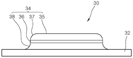
도 6은 본 발명의 일 실시예에 따른 결합부를 도시한 사시도이며, 도 7은 본 발명의 일 실시예에 따른 결합부를 도시한 정면도이다.FIG. 6 is a perspective view illustrating a coupling unit according to an embodiment of the present invention, and FIG. 7 is a front view illustrating a coupling unit according to an embodiment of the present invention.
도 1, 도 6 및 도 7에 도시된 바와 같이, 결합부(30)는 제2부재(20)를 관통하여 제1부재(10)를 향한 방향으로 돌출되며, 제1부재(10)와 같은 재질로 성형되어 스폿용접으로 제1부재(10)에 결합된다.As shown in Figs. 1, 6 and 7, the
일 실시예에 따른 결합부(30)는, 제2부재(20)의 일측면에 도포된 제1접착부재(40)와 마주하는 형상으로 설치되며 제2부재(20)의 외측에 적층되는 걸림부재(32)와, 걸림부재(32)에서 연장되어 제2부재(20)를 관통하며 제1부재(10)를 향한 방향으로 돌출되는 고정돌기(34)를 포함한다.The
걸림부재(32)는 제2부재(20)의 상측에 위치하며, 중공을 구비한 판 형상으로 형성된다. 걸림부재(32)의 내측에서 하측으로 돌출되어 통공홀부(22)를 관통하며 제1부재(10)에 접하는 고정돌기(34)는 베이스부재(35)와 측면부재(36)를 포함한다.The
베이스부재(35)는 제1부재(10)의 상측에 접한 상태로 용접이 이루어지며, 베이스부재(35)의 둘레에서 상측으로 연장된 측면부재(36)는 걸림부재(32)에 연결된다.The
제1곡면부(37)는 베이스부재(35)와 측면부재(36)의 경계면을 따라 곡면을 형성하므로, 고정돌기(34)가 통공홀부(22)의 내측으로 삽입되는 동작이 용이하게 이루어질 수 있도록 안내한다.The first
제2곡면부(38)는 측면부재(36)와 걸림부재(32)의 경계면을 따라 곡면을 형성하므로, 제1접착부재(40)와 접하는 모서리 부분의 면적을 증대시켜 접착력을 향상시킨다. Since the second
고정돌기(34)는 하측을 향하여 볼록한 형상으로 돌출되며, 고정돌기(34)의 내측에는 스폿용접기(60)의 제2전극(64)이 삽입되기 위한 홈부가 형성된다. The
결합부(30)와 제1부재(10)는 스폿용접 라인에서 용접이 이루어지는 스틸을 포함한 재질로 성형되며, 제2부재(20)는 유리 및 카본 섬유로 강화된 플라스틱계 복합재료인 에프알피(FRP: Fiber Reinforced Plastics)가 사용된다. 에프알피는 경량, 내식성, 성형성(成型性) 등이 뛰어난 고성능 및 고기능성 재료이다. 또는 제2부재(20)의 재료로 스틸이 아닌 다른 수지계 복합재료를 사용할 수도 있다.The joining
스틸인 제1부재(10)와 비철금속인 제2부재(20)의 접합시, 스틸 재질의 결합부(30)를 사용하여 이종소재의 접합이 이루어지므로, 기존의 용접라인을 사용할 수 있다.Since the joining of the different materials is performed by using the joining
스틸과 스틸을 스폿용접하는 기존의 용접라인을 그대로 활용할 수 있으므로, 차체 부품을 경량화시키기 위한 이종소재를 포함하는 복합체(1)의 생산에 소요되는 비용을 절감할 수 있다.The existing welding line for spot welding steel and steel can be utilized as it is, and thus it is possible to reduce the cost of producing the composite 1 including the different materials for lightening the body parts.
제1접착부재(40)는 제2부재(20)의 상측과 걸림부재(32)의 사이에 도포되므로, 제2부재(20)의 상측에 걸림부재(32)가 고정된다.Since the first
제2부재(20)를 사이에 두고 결합부(30)가 제1부재(10)에 고정되도록 스폿용접기(60)의 제1전극(62)과 제2전극(64)에 전기가 공급된다. 제1전극(62)은 제1부재(10)의 하측에 접하며 제2전극(64)은 결합부(30)의 고정돌기(34) 내측으로 삽입되어 베이스부재(35)의 상측에 접한다. 이러한 상태에서 제1전극(62)과 제2전극(64)으로 전기가 공급되어 스폿용접이 이루어진다.Electricity is supplied to the
도 5는 본 발명의 일 실시예에 따른 제1부재와 제2부재의 사이에 제2접착부재가 추가로 설치된 상태를 도시한 단면도이다.5 is a cross-sectional view showing a state in which a second adhesive member is additionally provided between the first member and the second member according to the embodiment of the present invention.
도 5에 도시된 바와 같이 이종소재를 포함하는 복합체(1)는, 접착성분을 포함하며 제1부재(10)와 제2부재(20)의 사이에 적층되며, 서로 마주하는 제1부재(10)와 제2부재(20)에 접착되는 제2접착부재(50)를 더 포함할 수 있다.As shown in Fig. 5, a composite 1 comprising a heterogeneous material is composed of a
따라서 제1부재(10)는 결합부(30)와 스폿용접되므로 제1부재(10)와 제2부재(20)의 결합이 이루어질 수 있으며, 제2접착부재(50)에 의해 제1부재(10)와 제2부재(20)의 결합이 이루어질 수 있다. 제1부재(10)와 제2부재(20)는 스폿용접과 접착제의 고정으로 2차에 걸쳐서 결합이 이루어지므로 향상된 결합력을 제공할 수 있다.The
이하에서는 첨부된 도면들을 참조하여 본 발명의 일 실시예에 따른 이종소재를 포함하는 복합체(1)의 제조방법을 상세히 설명한다.Hereinafter, a method for manufacturing a composite 1 including a heterogeneous material according to an embodiment of the present invention will be described in detail with reference to the accompanying drawings.
도 8은 본 발명의 일 실시예에 따른 이종소재를 포함하는 복합체(1)의 제조방법을 도시한 순서도이다.8 is a flowchart showing a method of manufacturing a composite 1 including a heterogeneous material according to an embodiment of the present invention.
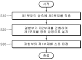
도 2와 도 8에 도시된 바와 같이, 본 발명의 일 실시예에 따른 이종소재를 포함하는 복합체(1)의 제조방법은, 제1부재(10)의 상측에 제1부재(10)와 다른 재질로 이루어진 제2부재(20)를 적층하는 단계를 갖는다.(S10) 이때 제1부재(10)와 결합부(30)는 스틸을 재질로 하며, 제2부재(20)는 비철금속을 재질로 한다.As shown in FIGS. 2 and 8, a method of manufacturing a composite 1 including a heterogeneous material according to an embodiment of the present invention includes the steps of forming a
그리고 도 3과 도 8에 도시된 바와 같이, 제1부재(10)와 같은 재질로 이루어지며 일측은 제2부재(20)의 외측에 위치하며 타측은 제2부재(20)를 관통하여 제1부재(10)를 향한 방향으로 돌출되는 결합부(30)를 제2부재(20)에 가조립하는 단계를 갖는다.(S20)As shown in Figs. 3 and 8, the
결합부(30)를 제2부재(20)에 가조립하는 단계에서, 결합부(30)와 제2부재(20)의 사이에 제1접착부재(40)가 설치되어 결합부(30)와 제2부재(20)의 마주하는 면에 접착된다. 따라서 결합부(30)와 제2부재(20)의 고정이 이루어진다.A
도 4와 도 8에 도시된 바와 같이, 결합부(30)를 스폿용접하여 제1부재(10)와 제2부재(20)를 고정시키는 단계를 갖는다.(S30) 제1전극(62)이 제1부재(10)의 하측에 접하며, 제2전극(64)이 결합부(30)의 내측으로 삽입되어 고정돌기(34)의 내측에 위치한 상태에서 제1전극(62)과 제2전극(64)에 전기가 공급된다. 따라서 결합부(30)는 제1부재(10)의 상측에 용접으로 고정되며, 제2부재(20)와 결합부(30)는 제1접착부재(40)의 사용과 결합부(30)의 걸림부재(32) 형상에 의해 고정된다.4 and 8, the
상술한 바와 같이, 본 발명에 따르면 스틸재질로 이루어진 결합부(30)가 비철금속 재질의 제2부재(20)를 관통하여 스틸재질로 이루어진 제1부재(10)에 용접되므로, 스틸재질을 용접하는 기존의 용접라인을 이용할 수 있어서 생산비를 절감할 수 있다.As described above, according to the present invention, since the engaging
본 발명은 도면에 도시된 실시예를 참고로 하여 설명되었으나 이는 예시적인 것에 불과하며, 당해 기술이 속하는 분야에서 통상의 지식을 가진 자라면 이로부터 다양한 변형 및 균등한 타 실시예가 가능하다는 점을 이해할 것이다. 따라서 본 발명의 진정한 기술적 보호범위는 아래의 특허청구범위에 의해서 정하여져야 할 것이다.
While the present invention has been particularly shown and described with reference to exemplary embodiments thereof, it will be understood by those skilled in the art that various changes and modifications may be made without departing from the scope of the invention as defined by the appended claims. will be. Accordingly, the true scope of the present invention should be determined by the following claims.
1: 이종소재를 포함하는 복합체
10: 제1부재
20: 제2부재
22: 통공홀부
30: 결합부
32: 걸림부재
34: 고정돌기
35: 베이스부재
36: 측면부재
37: 제1곡면부
38: 제2곡면부
40: 제1접착부재
50: 제2접착부재
60: 스폿용접기
62: 제1전극
64: 제2전극1: composite containing heterogeneous material
10: first member 20: second member
22: through hole 30:
32: engaging member 34:
35: base member 36: side member
37: first curved portion 38: second curved portion
40: first adhesive member 50: second adhesive member
60: Spot welder 62: First electrode 64: Second electrode
Claims (8)
상기 제1부재와 마주하며 상기 제1부재에 겹쳐지는 형상으로 설치되며, 상기 제1부재의 재질과 다른 재질로 이루어진 제2부재; 및
상기 제2부재를 관통하여 상기 제1부재를 향한 방향으로 돌출되며, 상기 제1부재와 같은 재질로 성형되는 결합부;를 포함하는 것을 특징으로 하는 이종소재를 포함하는 복합체.
A first plate-shaped member;
A second member provided in a shape facing the first member and overlapping the first member, the second member being made of a material different from the material of the first member; And
And an engaging portion protruding in a direction toward the first member through the second member and formed of the same material as the first member.
상기 제1부재와 상기 결합부는 스틸을 재질로 하며, 상기 제2부재는 비철금속을 재질로 하는 것을 특징으로 하는 이종소재를 포함하는 복합체.
The method according to claim 1,
Wherein the first member and the coupling portion are made of steel, and the second member is made of a non-ferrous material.
상기 제2부재와 상기 결합부의 사이에 도포되어 상기 제2부재에 상기 결합부를 고정시키는 제1접착부재;를 더 포함하는 것을 특징으로 하는 이종소재를 포함하는 복합체.
3. The method of claim 2,
And a first adhesive member applied between the second member and the engaging portion to fix the engaging portion to the second member.
상기 결합부는, 상기 제2부재의 일측면에 도포된 상기 제1접착부재와 마주하는 형상으로 설치되며, 상기 제2부재의 외측에 적층되는 걸림부재; 및
상기 걸림부재에서 연장되어 상기 제2부재를 관통하며, 상기 제1부재를 향한 방향으로 돌출되는 고정돌기;를 포함하는 것을 특징으로 하는 이종소재를 포함하는 복합체.
The method of claim 3,
The engaging portion is provided in a shape facing the first adhesive member coated on one side of the second member and is stacked on the outer side of the second member; And
And a fixing protrusion extending from the latching member and passing through the second member and protruding in a direction toward the first member.
접착성분을 포함하며 상기 제1부재와 상기 제2부재의 사이에 적층되며, 서로 마주하는 상기 제1부재와 상기 제2부재에 접착되는 제2접착부재;를 더 포함하는 것을 특징으로 하는 이종소재를 포함하는 복합체.
5. The method of claim 4,
Further comprising a second adhesive member which includes an adhesive component and is laminated between the first member and the second member and bonded to the first member and the second member facing each other, ≪ / RTI >
상기 제1부재와 같은 재질로 이루어지며, 일측은 상기 제2부재의 외측에 위치하며 타측은 상기 제2부재를 관통하여 상기 제1부재를 향한 방향으로 돌출된 결합부를 제2부재에 가조립하는 단계; 및
상기 결합부를 스폿용접하여 상기 제1부재와 상기 제2부재를 고정시키는 단계;를 포함하는 것을 특징으로 하는 이종소재를 포함하는 복합체의 제조방법.
Stacking a second member made of a different material from the first member on the upper side of the first member;
The step of joining the engaging part protruding in the direction toward the first member through the second member to the second member, the first member being made of the same material as the first member, the one side being located on the outer side of the second member, ; And
And fixing the first member and the second member by spot welding the joining portion. ≪ RTI ID = 0.0 > 11. < / RTI >
상기 제1부재와 상기 결합부는 스틸을 재질로 하며, 상기 제2부재는 비철금속을 재질로 하는 것을 특징으로 하는 이종소재를 포함하는 복합체의 제조방법.
The method according to claim 6,
Wherein the first member and the coupling portion are made of steel, and the second member is made of a non-ferrous material.
상기 결합부를 상기 제2부재에 가조립하는 단계에서, 상기 결합부와 상기 제2부재의 사이에 제1접착부재가 설치되는 것을 특징으로 하는 이종소재를 포함하는 복합체의 제조방법.8. The method of claim 7,
Wherein a first adhesive member is provided between the engaging portion and the second member in the step of assembling the engaging portion to the second member.
Priority Applications (1)
| Application Number | Priority Date | Filing Date | Title |
|---|---|---|---|
| KR1020160049240A KR20170120845A (en) | 2016-04-22 | 2016-04-22 | Composite of different materials |
Applications Claiming Priority (1)
| Application Number | Priority Date | Filing Date | Title |
|---|---|---|---|
| KR1020160049240A KR20170120845A (en) | 2016-04-22 | 2016-04-22 | Composite of different materials |
Publications (1)
| Publication Number | Publication Date |
|---|---|
| KR20170120845A true KR20170120845A (en) | 2017-11-01 |
Family
ID=60382798
Family Applications (1)
| Application Number | Title | Priority Date | Filing Date |
|---|---|---|---|
| KR1020160049240A KR20170120845A (en) | 2016-04-22 | 2016-04-22 | Composite of different materials |
Country Status (1)
| Country | Link |
|---|---|
| KR (1) | KR20170120845A (en) |
Cited By (1)
| Publication number | Priority date | Publication date | Assignee | Title |
|---|---|---|---|---|
| KR102028370B1 (en) * | 2018-06-15 | 2019-10-04 | (주)호원 | Apparatus for manufacturing composite of different materials |
-
2016
- 2016-04-22 KR KR1020160049240A patent/KR20170120845A/en not_active Application Discontinuation
Cited By (1)
| Publication number | Priority date | Publication date | Assignee | Title |
|---|---|---|---|---|
| KR102028370B1 (en) * | 2018-06-15 | 2019-10-04 | (주)호원 | Apparatus for manufacturing composite of different materials |
Similar Documents
| Publication | Publication Date | Title |
|---|---|---|
| US7819452B2 (en) | Automotive structural joint and method of making same | |
| CN107922008B (en) | Vehicle body structure of vehicle | |
| US6291792B1 (en) | Welded joint between a sheet-steel component and a light sheet metal component, and a welding method | |
| US10252472B2 (en) | Method for joining fiber-reinforced plastic material | |
| JP7012205B2 (en) | Joined structure | |
| JPWO2013073499A1 (en) | Automotive subframe | |
| KR20170120845A (en) | Composite of different materials | |
| KR20160082288A (en) | fastener for joining sheet | |
| JP2006281956A (en) | Sheet metal joint structure for vehicle body | |
| KR20180078041A (en) | Bonding method of different material | |
| JP2002321283A (en) | Ultrasonic fusion structure of plastic product | |
| JP2013126679A (en) | Panel connection structure | |
| JP4030370B2 (en) | Vehicle roof structure | |
| JP2003260737A (en) | Joint structure of injection-molded product | |
| KR102352109B1 (en) | Method for assembling different materials and different materials assembly | |
| KR100812414B1 (en) | Roof welding structure in vehicle | |
| KR102524663B1 (en) | Assembling method of lightweight sunroof assembly | |
| KR101729504B1 (en) | Adhering structure and method of different kinds of materials | |
| KR101689570B1 (en) | Adhering method of different kinds of materials | |
| JPWO2019224984A1 (en) | Body side panel | |
| KR20190076734A (en) | Hardware for different panel joining and different panel joining method using the same | |
| KR102104890B1 (en) | Clip for adhering different kinds materials and adhering structure of different kinds materials using thereof | |
| KR102225490B1 (en) | Multi material patchwork and manufacturing method thereof | |
| KR20210079808A (en) | Welding method for metal sheet and composite sheet | |
| KR20170069379A (en) | Connecting unit for composite |
Legal Events
| Date | Code | Title | Description |
|---|---|---|---|
| A201 | Request for examination | ||
| E902 | Notification of reason for refusal | ||
| E601 | Decision to refuse application |