RU2363617C2 - Aircraft landing gear manipulator system and aircraft with such system - Google Patents
Aircraft landing gear manipulator system and aircraft with such system Download PDFInfo
- Publication number
- RU2363617C2 RU2363617C2 RU2007115053/11A RU2007115053A RU2363617C2 RU 2363617 C2 RU2363617 C2 RU 2363617C2 RU 2007115053/11 A RU2007115053/11 A RU 2007115053/11A RU 2007115053 A RU2007115053 A RU 2007115053A RU 2363617 C2 RU2363617 C2 RU 2363617C2
- Authority
- RU
- Russia
- Prior art keywords
- chassis
- control circuit
- aircraft
- landing gear
- sash
- Prior art date
Links
- 238000012423 maintenance Methods 0.000 claims description 25
- 230000007246 mechanism Effects 0.000 claims description 18
- 230000014759 maintenance of location Effects 0.000 claims description 4
- 238000004891 communication Methods 0.000 claims description 2
- 230000000694 effects Effects 0.000 abstract 1
- 239000000126 substance Substances 0.000 abstract 1
- 238000004140 cleaning Methods 0.000 description 6
- 230000033001 locomotion Effects 0.000 description 5
- 238000000034 method Methods 0.000 description 5
- 239000012530 fluid Substances 0.000 description 3
- 230000005484 gravity Effects 0.000 description 2
- 230000000903 blocking effect Effects 0.000 description 1
- 238000005516 engineering process Methods 0.000 description 1
- 238000009434 installation Methods 0.000 description 1
- 238000002955 isolation Methods 0.000 description 1
- 238000004519 manufacturing process Methods 0.000 description 1
- 230000009347 mechanical transmission Effects 0.000 description 1
Images
Classifications
-
- B—PERFORMING OPERATIONS; TRANSPORTING
- B64—AIRCRAFT; AVIATION; COSMONAUTICS
- B64C—AEROPLANES; HELICOPTERS
- B64C25/00—Alighting gear
- B64C25/02—Undercarriages
- B64C25/08—Undercarriages non-fixed, e.g. jettisonable
- B64C25/10—Undercarriages non-fixed, e.g. jettisonable retractable, foldable, or the like
- B64C25/18—Operating mechanisms
- B64C25/26—Control or locking systems therefor
- B64C25/30—Control or locking systems therefor emergency actuated
-
- B—PERFORMING OPERATIONS; TRANSPORTING
- B64—AIRCRAFT; AVIATION; COSMONAUTICS
- B64C—AEROPLANES; HELICOPTERS
- B64C25/00—Alighting gear
- B64C25/02—Undercarriages
- B64C25/08—Undercarriages non-fixed, e.g. jettisonable
- B64C25/10—Undercarriages non-fixed, e.g. jettisonable retractable, foldable, or the like
- B64C25/18—Operating mechanisms
- B64C25/24—Operating mechanisms electric
-
- B—PERFORMING OPERATIONS; TRANSPORTING
- B64—AIRCRAFT; AVIATION; COSMONAUTICS
- B64C—AEROPLANES; HELICOPTERS
- B64C25/00—Alighting gear
- B64C25/02—Undercarriages
- B64C25/08—Undercarriages non-fixed, e.g. jettisonable
- B64C25/10—Undercarriages non-fixed, e.g. jettisonable retractable, foldable, or the like
- B64C25/18—Operating mechanisms
- B64C25/26—Control or locking systems therefor
-
- B—PERFORMING OPERATIONS; TRANSPORTING
- B64—AIRCRAFT; AVIATION; COSMONAUTICS
- B64F—GROUND OR AIRCRAFT-CARRIER-DECK INSTALLATIONS SPECIALLY ADAPTED FOR USE IN CONNECTION WITH AIRCRAFT; DESIGNING, MANUFACTURING, ASSEMBLING, CLEANING, MAINTAINING OR REPAIRING AIRCRAFT, NOT OTHERWISE PROVIDED FOR; HANDLING, TRANSPORTING, TESTING OR INSPECTING AIRCRAFT COMPONENTS, NOT OTHERWISE PROVIDED FOR
- B64F5/00—Designing, manufacturing, assembling, cleaning, maintaining or repairing aircraft, not otherwise provided for; Handling, transporting, testing or inspecting aircraft components, not otherwise provided for
- B64F5/60—Testing or inspecting aircraft components or systems
Abstract
Description
Область техникиTechnical field
Настоящее изобретение относится к системе манипулирования шасси летательного аппарата. Системой манипулирования шасси летательного аппарата называют систему, позволяющую обеспечить выпуск и уборку шасси по отношению к фюзеляжу летательного аппарата. Действительно, в большинстве летательных аппаратов шасси является убираемым, то есть это шасси смонтировано шарнирным образом в отсеке шасси, располагающемся внутри фюзеляжа летательного аппарата. Таким образом, в фазе крейсерского полета шасси остается внутри фюзеляжа, в отсеке шасси, который закрывается при помощи системы створок. Перед посадкой летательного аппарата шасси выпускается и выходит из отсека шасси после раскрытия створок. Предлагаемое изобретение относится также к системе управления раскрытием створок и выпуском шасси при нормальном функционировании, при резервном функционировании и в фазе технического обслуживания.The present invention relates to an aircraft landing gear manipulation system. A system for manipulating the landing gear of an aircraft is called a system that allows for the release and cleaning of the landing gear in relation to the fuselage of the aircraft. Indeed, in most aircraft, the landing gear is retractable, that is, this landing gear is hinged in the compartment of the landing gear located inside the fuselage of the aircraft. Thus, in the phase of the cruise flight, the landing gear remains inside the fuselage, in the landing gear compartment, which is closed by a sash system. Before landing the aircraft, the landing gear is released and leaves the landing gear compartment after the flaps open. The present invention also relates to a control system for the opening of the leaves and the release of the chassis during normal operation, during standby operation and in the maintenance phase.
Предлагаемое изобретение находит применение в области авиационной техники и, в частности, в области выпуска и уборки шасси летательного аппарата.The present invention finds application in the field of aviation technology and, in particular, in the field of production and cleaning of the aircraft chassis.
Уровень техникиState of the art
В настоящее время преобладающая часть летательных аппаратов содержит одну или несколько убираемых стоек шасси. Каждая стойка шасси, называемая просто шасси, установлена в ложементе фюзеляжа, называемом "отсеком шасси". В процессе выполнения крейсерского полета отсек шасси закрыт при помощи системы створок, чтобы сохранить требуемый аэродинамический профиль летательного аппарата. При выполнении фазы посадки или взлета шасси находится в выпущенном положении, то есть в положении его выхода из отсека размещения в так называемом нижнем положении. Перед осуществлением фазы посадки летательного аппарата шасси выпускается из своего отсека, то есть оно переходит из убранного положения в выпущенное или нижнее положение, обычно в автоматическом режиме по команде, выдаваемой пилотом.Currently, the predominant part of the aircraft contains one or more retractable landing gear. Each landing gear, simply called the landing gear, is installed in the lodgement of the fuselage, called the "landing gear compartment." During cruising, the landing gear compartment is closed using a system of flaps in order to maintain the desired aerodynamic profile of the aircraft. During the landing or take-off phase, the chassis is in the released position, that is, in the position of its exit from the placement compartment in the so-called lower position. Before the landing phase of the aircraft, the landing gear is released from its compartment, that is, it moves from the retracted position to the released or lower position, usually in automatic mode, on command issued by the pilot.
В процессе так называемого "нормального" функционирования шасси выпускается автоматически из своего отсека. В случае того или иного повреждения основной системы резервный контур управления обеспечивает механический выпуск шасси.In the process of the so-called "normal" functioning, the chassis is automatically released from its compartment. In the event of one or another damage to the main system, a redundant control loop provides mechanical release of the chassis.
В процессе нормального функционирования шасси имеет возможность быть выпущенным только после раскрытия створок отсека шасси. Таким образом, предусмотрена определенная последовательность функционирования системы выпуска шасси, в соответствии с которой прежде всего открываются створки отсека шасси, а затем выпускается собственно стойка шасси. Обратная последовательность функционирования позволяет обеспечить уборку шасси в отсек шасси после взлета летательного аппарата.In the process of normal functioning of the chassis has the ability to be released only after the opening of the wings of the compartment. Thus, a certain sequence of operation of the landing gear system is provided, in accordance with which, first of all, the doors of the chassis compartment are opened, and then the landing gear itself is released. The reverse sequence of operation allows the landing gear to be cleaned into the landing gear compartment after take-off of the aircraft.
При резервном функционировании шасси выходит из своего отсека под действием силы тяжести, обеспечивая при этом раскрытие створок отсека. При этом створки отсека шасси образованы одной или несколькими основными створками и одной или несколькими вторичными створками, независимыми от основных створок. Основная створка отсека шасси предназначена для того, чтобы быть снова закрытой после того, как шасси перешло в свое нижнее или выпущенное положение. Вторичные створки предназначены для того, чтобы пропустить стойку шасси и они, таким образом, остаются открытыми до тех пор, пока шасси остается выпущенным.During standby operation, the chassis leaves its compartment under the action of gravity, while ensuring the opening of the shutters of the compartment. The flaps of the chassis compartment are formed by one or more main flaps and one or more secondary flaps, independent of the main flaps. The main flap of the chassis compartment is designed to be closed again after the chassis has moved to its lower or extended position. The secondary flaps are designed to skip the landing gear and thus remain open as long as the chassis remains extended.
Когда летательный аппарат находится на земле, основная створка отсека шасси находится в закрытом положении, причем вторичные створки остаются открытыми, оставляя свободным только минимально необходимое пространство, требуемое для прохождения стойки шасси. Однако и в этом случае может возникнуть необходимость в открытии основной створки, например, для выполнения операций технического обслуживания.When the aircraft is on the ground, the main wing of the landing gear compartment is in the closed position, with the secondary wings remain open, leaving only the minimum necessary space required to pass the landing gear. However, in this case, it may be necessary to open the main leaf, for example, to perform maintenance operations.
В настоящее время система выпуска шасси представляет собой систему смешанного типа, то есть систему, в которой используются несколько источников энергии. Более конкретно в процессе нормального функционирования в этой системе используется энергия гидравлической системы, связанной с электрической энергией. При резервном функционировании в этой системе используется электрическая энергия, связанная с механической кинематической цепью. В процессе функционирования в рамках технического обслуживания в этой системе используется энергия обслуживающего персонала, связанная с механической энергией.Currently, the chassis exhaust system is a mixed type system, that is, a system that uses several energy sources. More specifically, during normal operation, the system uses the energy of a hydraulic system associated with electrical energy. When backed up, this system uses electrical energy associated with a mechanical kinematic circuit. In the process of functioning as part of maintenance, this system uses the energy of the operating personnel associated with mechanical energy.
Для обеспечения нормального функционирования система содержит следующие элементы:To ensure normal operation, the system contains the following elements:
клапан, управляемый электрически, или электроклапан, который обеспечивает соединение специфического гидравлического контура отсека шасси с общей гидравлической системой летательного аппарата. Управление электроклапаном выполняется из кабины экипажа и обеспечивает подключение к функционированию гидравлического контура отсека шасси;an electrically controlled valve or an electrovalve that connects the specific hydraulic circuit of the landing gear compartment to the general hydraulic system of the aircraft. The control of the electrovalve is carried out from the cockpit and provides connection to the functioning of the hydraulic circuit of the chassis compartment;
контур гидравлического и электрического управления створками.hydraulic and electric sash control circuit.
Этот контур содержитThis circuit contains
- по меньшей мере один замок блокировки створки, который обеспечивает удержание створки в закрытом положении,- at least one lock to lock the sash, which ensures that the sash is in the closed position,
- по меньшей мере один гидравлический силовой цилиндр, который обеспечивает подвижность створки,- at least one hydraulic ram, which provides sash mobility,
- электроклапан створки, который обеспечивает управление гидравлическим силовым цилиндром створки.- sash electrovalve, which provides control of the sash hydraulic ram.
В настоящее время цепь гидравлического и электрического управления створкой представляет собой гидравлический контур, называемый контуром створки. Клапан створки представляет собой точку входа этой цепи управления. Клапан управляется электрически. В случае когда клапан открыт, текучая среда протекает в контур управления, обеспечивая разблокирование замка створки и питание гидравлического силового цилиндра створки, который обеспечивает открытие этой створки.Currently, the sash hydraulic and electrical control circuit is a hydraulic circuit called the sash circuit. The sash valve is the entry point of this control circuit. The valve is electrically controlled. When the valve is open, fluid flows into the control circuit, enabling the sash lock to be unlocked and the sash hydraulic cylinder to open, which allows the sash to open.
Кроме того, данная система содержит контур управления шасси, содержащийIn addition, this system comprises a chassis control loop comprising
по меньшей мере один замок удержания шасси, который обеспечивает удержание шасси в убранном положении,at least one lock holding the chassis, which ensures that the chassis is in the retracted position,
по меньшей мере один гидравлический силовой цилиндр шасси, который обеспечивает подвижность шасси,at least one hydraulic power cylinder of the chassis, which provides mobility of the chassis,
электроклапан шасси, который обеспечивает управление гидравлическим силовым цилиндром шасси.Chassis solenoid valve that controls the hydraulic power cylinder of the chassis.
В настоящее время цепь управления перемещением шасси представляет собой гидравлический контур, называемый контуром шасси. Клапан шасси представляет собой входную точку этой цепи управления. Клапан управляется электрически. В том случае когда клапан открыт, текучая среда попадает в систему цепи управления, обеспечивая разблокирование замка удержания шасси и питание гидравлического силового цилиндра шасси, что обеспечивает выпуск стойки шасси.Currently, the chassis movement control circuit is a hydraulic circuit called the chassis circuit. The chassis valve is the entry point to this control circuit. The valve is electrically controlled. In the case when the valve is open, the fluid enters the control circuit system, providing unlocking of the chassis lock and power supply to the hydraulic chassis power cylinder, which ensures the release of the landing gear.
В том случае когда шасси находится в своем нижнем или выпущенном положении, питание контура шасси прекращается. Гидравлический силовой цилиндр створки при этом приводится в действие для того, чтобы закрыть основные створки, причем в этом случае вторичные створки остаются открытыми, оставляя свободным лишь минимальное пространство, необходимое для прохождения стойки шасси. После закрытия основных створок питание гидравлического силового цилиндра створок прекращается, чтобы исключить возможность несвоевременного раскрытия створок. Затем специфический гидравлический контур отсека шасси отключается от общего гидравлического контура.When the chassis is in its lower or extended position, the power to the chassis circuit is cut off. The flap hydraulic actuator is then actuated in order to close the main flaps, in which case the secondary flaps remain open, leaving only the minimum space necessary to pass the landing gear. After closing the main leaves, the power of the hydraulic power cylinder of the leaves is stopped to exclude the possibility of untimely opening of the leaves. Then, the specific hydraulic circuit of the chassis compartment is disconnected from the general hydraulic circuit.
Открытие створок и последующий выпуск шасси обеспечиваются при помощи гидравлического контура, последовательно управляемого при помощи электронного вычислителя. Таким образом, факт наличия электрически управляемого клапана, предназначенного для створок, и другого электрически управляемого клапана, предназначенного для выпуска шасси, позволяет обеспечить открытие клапанов в различные моменты времени, в той или иной степени отличающиеся друг от друга, что позволяет обеспечить определенную последовательность в выполнении операций открытия створок и выпуска шасси.The opening of the wings and the subsequent release of the chassis are ensured by a hydraulic circuit, sequentially controlled by an electronic computer. Thus, the fact of the presence of an electrically controlled valve designed for sashes, and another electrically controlled valve designed to release the chassis, allows the valves to open at various points in time, to one degree or another different from each other, which allows for a certain sequence in execution sash opening and landing gear operations.
Последовательность операций уборки шасси в предназначенный для его размещения отсек является обратной по отношению к последовательности операций выпуска шасси. Эта последовательность операций содержит те же этапы, что и последовательность для выпуска шасси, и управляется электрически и гидравлически, но осуществляется в обратном порядке.The sequence of operations for cleaning the chassis in the compartment intended for its placement is the reverse of the sequence of operations for the release of the chassis. This sequence of operations contains the same steps as the sequence for the release of the chassis, and is controlled electrically and hydraulically, but is carried out in the reverse order.
Таким образом, в процессе нормального функционирования основной клапан управления и другие клапаны гидравлического контура управляются электрически из кабины экипажа, например, при помощи бортового блока управления положением шасси летательного аппарата, действующего по команде пилота.Thus, during normal operation, the main control valve and other valves of the hydraulic circuit are electrically controlled from the cockpit, for example, using the on-board control unit for the position of the aircraft landing gear, acting on the command of the pilot.
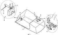
В случае отказа общего гидравлического контура или специфического гидравлического контура отсека шасси предусмотрен резервный вариант функционирования. Этот резервный вариант функционирования (называемый также английским термином Free Fall) осуществляется при помощи специальной системы, представленной на фиг.1, где показана резервная система, установленная в отсеке шасси.In the event of a failure of the general hydraulic circuit or a specific hydraulic circuit of the chassis compartment, a redundant operation option is provided. This backup version of the operation (also called the English term Free Fall) is carried out using a special system, presented in figure 1, which shows the backup system installed in the chassis compartment.
На фиг.1 схематически представлен отсек шасси, в котором установлена классическая резервная система, содержащая приводной механизм 1, управляемый электрически, например, при помощи блока управления перемещением шасси. Приводной механизм 1 механически связан посредством кинематической цепи 2 (называемой также системой тяг, качалок и рычагов) с замком 7 удержания шасси и с клапаном 4. Показана более подробно цепь управления створкой 6 вместе с ее замком 3 блокировки и цепь 5 управления перемещением шасси вместе с замком 7 удержания. Клапан 4 позволяет обеспечить свободное скольжение поршней в гидравлических силовых цилиндрах створок и стойки шасси.1 schematically shows a compartment of a chassis in which a classic backup system is installed, comprising a
В резервном функционировании задание последовательности операций разблокирования замков створок и стойки шасси обеспечивается механически путем использования приводного элемента 1.In standby operation, setting the sequence of operations for unlocking the locks of the wings and the landing gear is provided mechanically by using the
Разумеется понятно, что в соответствии со способом резервного варианта функционирования створки остаются открытыми и шасси не может быть убрано.Of course, it is clear that in accordance with the method of the backup version of the functioning of the sash remain open and the chassis cannot be removed.
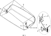
В соответствии с другим способом функционирования системы выпуска шасси, когда летательный аппарат находится на земле, важно, по соображениям технического обслуживания шасси, иметь возможность открыть основную створку отсека шасси вручную. Действительно, в случае когда летательный аппарат находится на земле и опирается на шасси, эта створка закрыта. Персонал технического обслуживания летательного аппарата должен иметь возможность проникнуть в отсек шасси, чтобы осуществить необходимые операции контроля. При нахождении летательного аппарата на земле гидравлическая энергия отсутствует, поскольку двигатели летательного аппарата выключены. При этом открытие створки осуществляется при помощи механической рукоятки, расположенной в непосредственной близости от створки отсека шасси. Пример реализации классической системы технического обслуживания представлен на фиг.2, где схематически показана система технического обслуживания, которая фиксирована в отсеке шасси.In accordance with another method of operating the landing gear system when the aircraft is on the ground, it is important, for reasons of landing gear maintenance, to be able to manually open the main wing of the landing gear compartment. Indeed, in the case when the aircraft is on the ground and rests on the landing gear, this sash is closed. Aircraft maintenance personnel should be able to enter the landing gear compartment to carry out the necessary control operations. When the aircraft is on the ground, there is no hydraulic energy because the aircraft’s engines are turned off. The opening of the sash is carried out using a mechanical handle located in the immediate vicinity of the sash of the chassis compartment. An example implementation of the classic maintenance system is presented in figure 2, which schematically shows a maintenance system, which is fixed in the compartment of the chassis.
Система технического обслуживания содержит механическую рукоятку 8, связанную при помощи кинематической цепи (называемой также системой тяг, качалок и рычагов) с цепью управления створками 6. Кинематическая цепь 9 может представлять собой шарнирный приводной механизм, закрепленный при помощи направляющих на стенках отсека шасси. Приводя в действие рукоятку 8, кинематическая цепь 9 приводится в движение, управляя открытием основной створки. Более конкретно, поворачивая рукоятку 8, например, на угол 90°, кинематическая цепь 9 приводится в линейное перемещение, которое реализует определенную последовательность операций:The maintenance system contains a
изоляцию специального гидравлического контура питания гидравлических силовых цилиндров створок (в целях безопасности и для исключения возможности, в случае аварийного подключения к общему гидравлическому контуру, несвоевременного закрытия основной створки);isolation of a special hydraulic power supply circuit for the hydraulic leaf power cylinders (for safety reasons and to exclude the possibility, in case of emergency connection to the general hydraulic circuit, of untimely closing of the main leaf);
открытие клапана 10, позволяющего обеспечить свободу циркуляции текучей среды в камере гидравлического силового цилиндра створки, чтобы гидравлический силовой цилиндр не противодействовал открытию створки;opening the
механическую разблокировку замка основной створки.mechanical unlocking of the main sash lock.
Основная створка открывается под действием силы тяжести или вручную.The main sash opens by gravity or manually.
В системе технического обслуживания ручная рукоятка закреплена на фюзеляже летательного аппарата, обычно в закрытой полости, размещенной в непосредственной близости от створки, т.е. она располагается на относительно большой высоте по отношению к земле. Вследствие этого персонал технического обслуживания должен, в некоторых случаях, подниматься на стремянку, чтобы достать до рукоятки и привести ее в действие для открытия створки.In a maintenance system, a hand grip is mounted on the fuselage of an aircraft, usually in a closed cavity located in close proximity to the sash, i.e. it is located at a relatively high height relative to the ground. As a result, maintenance personnel must, in some cases, climb the ladder to reach the handle and actuate it to open the sash.
Кроме того, как об этом уже было сказано выше, конструкция управления выпуском и уборкой шасси является достаточно сложной и требует наличия значительного числа громоздких элементов, например, таких как кинематические цепи, которые являются различными в зависимости от режима функционирования.In addition, as already mentioned above, the design for controlling the release and cleaning of the chassis is quite complex and requires a significant number of bulky elements, such as kinematic chains, which are different depending on the mode of operation.
Кроме того, чтобы иметь возможность быть использованными в различных режимах функционирования, некоторые элементы управляются от различных источников энергии, что приводит к усложнению этих элементов. Например, замок шасси содержит два независимых входа: гидравлический вход, предназначенный для режима нормального функционирования, и механический вход, предназначенный для функционирования в резервном режиме. Кроме того, замок створки содержит три раздельных и независимых входа: гидравлический вход, предназначенный для режима нормального функционирования, механический вход, предназначенный для функционирования в резервном режиме, и специальный механический вход, предназначенный для проведения операций технического обслуживания. Из этого следуют соответствующие габариты соединительных элементов с цепями управления.In addition, in order to be able to be used in various modes of operation, some elements are controlled from various energy sources, which leads to the complexity of these elements. For example, a chassis lock contains two independent inputs: a hydraulic input, designed for normal operation, and a mechanical input, designed to function in standby mode. In addition, the sash lock contains three separate and independent inputs: a hydraulic input, designed for normal operation, a mechanical input, designed to function in standby mode, and a special mechanical input, designed for maintenance operations. From this follow the corresponding dimensions of the connecting elements with control circuits.
Кроме того, замки створки и шасси располагаются в негерметизированных отсеках, не подвергающихся наддуву, тогда как цепи управления, главным образом, располагаются в наддуваемых и герметизированных отсеках. Вследствие этого должны быть приняты все меры предосторожности, чтобы обеспечить возможность для упомянутой системы тяг, качалок и рычагов проходить через стенки наддуваемых герметизированных отсеков, не изменяя давления в этих отсеках.In addition, the sash and chassis locks are located in unpressurized compartments that are not pressurized, while the control circuits are mainly located in pressurized and pressurized compartments. As a consequence, all safety precautions must be taken to ensure that the mentioned traction system, rocking chairs and levers can pass through the walls of pressurized pressurized compartments without changing the pressure in these compartments.
В настоящее время производители летательных аппаратов стремятся разрабатывать летательные аппараты, позволяющие транспортировать в одном полете все более объемные и тяжеловесные грузы. Для этого они стремятся разрабатывать летательные аппараты все более крупных размеров. Такие летательные аппараты могут иметь большее количество стоек шасси, чем летательные аппараты классического типа, что умножает упомянутые в предшествующем изложении проблемы, связанные с шасси. Кроме того, увеличение количества стоек шасси существенно увеличивает массу летательного аппарата.Currently, aircraft manufacturers are striving to develop aircraft that allow the transport of increasingly voluminous and heavy loads in one flight. To do this, they strive to develop aircraft of ever larger sizes. Such aircraft may have more landing gear than classical type aircraft, which multiplies the problems associated with the landing gear mentioned in the previous discussion. In addition, an increase in the number of landing gear significantly increases the mass of the aircraft.
Кроме того, в этих летательных аппаратах очень больших размеров колеса шасси могут быть более объемными, чем колеса шасси классического типа, что приводит к размещению фюзеляжа на большей высоте по отношению к земле. По соображениям массы и размещения упомянутая выше рукоятка должна быть установлена в негерметизированной и не подлежащей наддуву области, что требует выполнения отверстия для прохождения системы тяг, качалок и рычагов в стенке наддуваемого отсека с возникновением всех проблем, связанных с наддувом этого отсека. При этом рукоятка будет находиться очень далеко от земли, на высоте, превышающей высоту человеческого роста, с повышенной опасностью падения людей, выполняющих техническое обслуживание.In addition, in these very large size aircraft, the landing gear wheels can be more voluminous than the classic landing gear wheels, which leads to the fuselage being placed at a higher height relative to the ground. For reasons of weight and placement, the handle mentioned above should be installed in an unsealed and non-pressurized area, which requires a hole to pass through the system of rods, rocking chairs and levers in the wall of the pressurized compartment with all the problems associated with pressurization of this compartment. At the same time, the handle will be very far from the earth, at a height exceeding the height of human growth, with an increased danger of falling people performing maintenance.
Краткое изложение существа изобретенияSummary of the invention
Технической задачей предлагаемого изобретения является устранение отмеченных недостатков. Для решения этой технической задачи согласно изобретению предложена система манипулирования шасси летательного аппарата, в которой управление открытием створки и управление выпуском шасси реализуются электрически в любом режиме функционирования. Электрическая энергия всегда присутствует на борту летательного аппарата либо в результате функционирования его двигателей, при нормальном функционировании, или в случае потери гидравлической энергии, либо благодаря резервному воздушному винту, позволяющему генерировать количество электрической энергии, достаточное для управления самолетом в режиме повреждения (потеря гидравлической и электрической энергии), либо с использованием в случае необходимости вспомогательного наземного источника энергии (аккумуляторные батареи, наземные генераторные установки и т.п.) в фазе технического обслуживания. Таким образом, в данном изобретении предлагается заменить гидравлические и механические приводные механизмы цепей управления створками и шасси на электрические приводные механизмы в процессе нормального функционирования, резервного функционирования и функционирования при техническом обслуживании.The technical task of the invention is to remedy the noted drawbacks. To solve this technical problem, according to the invention, there is provided a system for manipulating the landing gear of an aircraft, in which the leaf opening control and landing gear control are realized electrically in any operating mode. Electric energy is always present on board the aircraft, either as a result of the operation of its engines, during normal operation, or in the event of loss of hydraulic energy, or due to a reserve propeller that allows generating enough electric energy to control the aircraft in damage mode (loss of hydraulic and electrical energy), or using, if necessary, an auxiliary ground-based energy source (batteries, ground e generating system and the like) in the maintenance phase. Thus, in this invention, it is proposed to replace the hydraulic and mechanical drive mechanisms of the leaf and chassis control circuits with electric drive mechanisms during normal operation, back-up operation and operation during maintenance.
Более конкретно предлагаемое изобретение относится к системе манипулирования шасси летательного аппарата, установленного на шарнирах в отсеке шасси, закрытом системой створок, содержащей:More specifically, the present invention relates to a system for manipulating the landing gear of an aircraft mounted on hinges in a compartment of the landing gear, closed by a sash system comprising:
общий блок управления отсеком шасси, предназначенный для включения различных операций,a common control unit for the chassis compartment, designed to enable various operations,
цепь управления створками,sash control circuit
цепь управления шасси,chassis control circuit
и характеризующейся тем, что общий блок управления, цепь управления створками и цепь управления шасси управляются при помощи источника электрической энергии в случае, когда летательный аппарат находится в режиме нормального функционирования, в режиме резервного функционирования и в фазе технического обслуживания.and characterized in that the common control unit, the leaf control circuit and the landing gear control circuit are controlled by an electric power source in the case when the aircraft is in normal operation, in standby mode and in the maintenance phase.
В предлагаемом изобретении предпочтительноIn the present invention, preferably
цепь управления створками содержит по меньшей мере одно электрически управляемое устройство блокировки створок, по меньшей мере один приводной орган створки и электрически управляемый орган управления этим приводным органом,the leaf control circuit comprises at least one electrically controlled leaf blocking device, at least one leaf drive element and an electrically controlled leaf control element,
цепь управления шасси содержит по меньшей мере одно электрически управляемое устройство удержания шасси, по меньшей мере один приводной орган шасси и электрически управляемый орган управления этим приводным органом,the chassis control circuit includes at least one electrically controlled chassis retention device, at least one chassis drive member and an electrically controlled chassis control member,
при нормальном функционировании источник энергии представляет собой общее электрическое питание летательного аппарата,during normal operation, the energy source is the total electrical power of the aircraft,
при резервном функционировании источник энергии представляет собой общее электрическое питание летательного аппарата или вторичный источник электрического питания летательного аппарата, содержащий воздушный винт, если общее электрическое питание летательного аппарата отсутствует,in standby operation, the energy source is a general electrical power supply of the aircraft or a secondary electric power supply of the aircraft containing a propeller, if the general electrical power of the aircraft is absent,
в фазе технического обслуживания источником энергии является источник электрической энергии, имеющийся на летательном аппарате или вспомогательный наземный источник электрической энергии,in the maintenance phase, the energy source is an electric energy source available on an aircraft or an auxiliary ground source of electric energy,
цепь управления створками содержит по меньшей мере один электрический приводной механизм, связанный с устройством блокировки створки, и электрический приводной механизм, связанный с органом управления приводным органом створки,the sash control circuit comprises at least one electric drive mechanism associated with the sash lock device, and an electric drive mechanism associated with the control member of the sash drive member,
цепь управления шасси содержит по меньшей мере один электрический приводной механизм, связанный с устройством удержания шасси, и электрический приводной механизм, связанный с органом управления приводным органом шасси,the chassis control circuit includes at least one electric drive mechanism associated with the chassis holding device, and an electric drive mechanism associated with a control member of the chassis drive member,
цепь управления створками содержит орган электрического управления, обеспечивающий управление открытием основной створки в фазе технического обслуживания,the leaf control circuit contains an electric control element that controls the opening of the main leaf in the maintenance phase,
общий блок управления электрически связан с цепью управления створками и с цепью управления шасси,the common control unit is electrically connected to the leaf control circuit and to the chassis control circuit,
электрическая связь между общим блоком управления и цепями управления створками и шасси, представляет собой проводную связь,The electrical connection between the common control unit and the leaf and chassis control circuits is a wire connection,
общий блок управления обеспечивает задание последовательности приведения в действие устройств блокировки створок и удержания шасси и приводных органов.the common control unit provides a sequence of actuating devices for locking the wings and holding the chassis and drive elements.
Предлагаемое изобретение относится также к летательному аппарату с такой системой выполнения операций с шасси.The present invention also relates to an aircraft with such a system for performing operations with the landing gear.
Краткое описание чертежейBrief Description of the Drawings
В дальнейшем изобретение поясняется описанием предпочтительных вариантов выполнения со ссылками на сопровождающие чертежи, на которых:The invention is further explained in the description of the preferred embodiments with reference to the accompanying drawings, in which:
фиг.1 изображает известную систему выпуска шасси при резервном функционировании;figure 1 depicts a known system for the release of the chassis in redundant operation;
фиг.2 изображает известную систему выпуска шасси в фазе технического обслуживания;figure 2 depicts a known system for the release of the chassis in the phase of maintenance;
фиг.3 изображает систему выпуска шасси согласно изобретению.figure 3 depicts a chassis exhaust system according to the invention.
Подробное описание предпочтительных вариантов реализации изобретенияDETAILED DESCRIPTION OF PREFERRED EMBODIMENTS
Согласно изобретению предлагается система манипулирования шасси с электрическими органами управления. Система представлена на фиг.3.According to the invention, a chassis manipulation system with electric controls is provided. The system is presented in figure 3.
Система манипулирования шасси содержит цепь 16 управления створками и цепь 15 управления шасси, причем сами эти цепи управляются общим блоком управления.The chassis manipulation system comprises a sash control circuit 16 and a chassis control circuit 15, these circuits themselves being controlled by a common control unit.
В соответствии с предлагаемым изобретением цепь 16 управления створками содержит по меньшей мере одно устройство блокировки каждой створки, по меньшей мере один приводной орган каждой створки и орган управления этим приводным органом. Как было указано выше, отсек шасси летательного аппарата содержит несколько створок, т.е. одну или несколько основных створок и по меньшей мере одну вторичную створку. Предлагаемое изобретение будет описано в варианте с одной основной створкой шасси. Следует отметить, что изобретение также может быть применено ко всем основным створкам летательного аппарата (в случае когда летательный аппарат имеет несколько основных створок) и к одной или нескольким вторичным створкам летательного аппарата, причем понятно, что в этом случае эти одна или несколько вторичных створок остаются открытыми, пока шасси находится в выпущенном положении.In accordance with the invention, the sash control circuit 16 comprises at least one locking device for each sash, at least one drive member of each sash and a control member for this drive member. As mentioned above, the aircraft compartment contains several wings, i.e. one or more primary leaflets and at least one secondary leaflet. The present invention will be described in the embodiment with a single main leaf of the chassis. It should be noted that the invention can also be applied to all the main wings of the aircraft (in the case when the aircraft has several main wings) and to one or more secondary wings of the aircraft, and it is clear that in this case these one or more secondary wings remain open while the chassis is in the released position.
Каждая створка приводится в действие посредством по меньшей мере одного приводного органа типа гидравлического силового цилиндра или электрического двигателя. В последующем изложении будет считаться, что приводной орган представляет собой гидравлический силовой цилиндр. Гидравлические силовые цилиндры управляются при помощи органа 18 управления. Этот орган управления может представлять собой электроклапан, то есть электрически управляемый гидравлический клапан при помощи электрического привода.Each leaf is actuated by at least one drive member such as a hydraulic ram or electric motor. In the following statement, it will be considered that the drive member is a hydraulic ram. Hydraulic power cylinders are controlled by a control member 18. This control may be an electrovalve, that is, an electrically controlled hydraulic valve with an electric actuator.
Каждая створка удерживается в заблокированном положении при помощи устройства 17 блокировки. Устройство блокировки может представлять собой замок, или самоблокирующийся подъемник, или же систему тяг и рычагов, связанных с шасси и позволяющих при помощи соответствующей кинематики открывать створку в том случае, когда начинается фаза выпуска шасси. В последующем изложении принято, что устройство блокировки представляет собой электрически управляемый замок. Таким образом, в соответствии с предлагаемым изобретением замок блокировки связан с электрическим приводным механизмом.Each leaf is held in a locked position by the locking device 17. The locking device can be a lock, or a self-locking lift, or a system of rods and levers connected with the chassis and allowing using the appropriate kinematics to open the sash in the case when the landing phase of the chassis begins. In the following statement, it is assumed that the locking device is an electrically controlled lock. Thus, in accordance with the invention, the lock lock is associated with an electric drive mechanism.
Другими словами, в соответствии с предпочтительным вариантом реализации предлагаемого изобретения цепь управления створкой содержитIn other words, in accordance with a preferred embodiment of the invention, the sash control circuit comprises
электрически управляемый замок блокировки при помощи электрического приводного механизма,an electrically operated lock with an electric drive mechanism,
гидравлический силовой цилиндр створки, управляемый гидравлически посредством электроклапана.sash hydraulic cylinder, hydraulically controlled by an electrovalve.
Согласно изобретению цепь 15 управления шасси содержит устройство удержания шасси, по меньшей мере один приводной орган шасси и орган управления этим приводным органом. Таким образом, шасси приводится в действие посредством приводного органа типа гидравлического силового цилиндра или электрического двигателя. В последующем изложении будет считаться, что приводной орган представляет собой гидравлический силовой цилиндр. Этот гидравлический силовой цилиндр управляется посредством органа 14 управления, представляющего собой электроклапан.According to the invention, the chassis control circuit 15 comprises a chassis holding device, at least one chassis drive member and a control member for this drive member. Thus, the chassis is driven by a drive member such as a hydraulic ram or electric motor. In the following statement, it will be considered that the drive member is a hydraulic ram. This hydraulic power cylinder is controlled by a control member 14, which is an electrovalve.
В убранном положении шасси удерживается при помощи устройства 13 удержания, которое может представлять собой замок или самоблокирующийся подъемник. В последующем изложении будет считаться, что это устройство удержания представляет собой замок, управляемый электрически. В соответствии с предлагаемым изобретением замок удержания связан с электрическим приводным механизмом.In the retracted position, the chassis is held by a holding device 13, which may be a lock or a self-locking lift. In the following, it will be deemed that this restraint is an electrically operated lock. In accordance with the invention, the retention lock is connected to an electric drive mechanism.
Таким образом, в соответствии с предпочтительным вариантом реализации предлагаемого изобретения цепь управления шасси содержитThus, in accordance with a preferred embodiment of the invention, the chassis control circuit comprises
замок удержания шасси, электрически управляемый при помощи электрического приводного механизма, иa chassis retention lock electrically controlled by an electric drive mechanism, and
гидравлический силовой цилиндр шасси, управляемый гидравлически при помощи электроклапана.hydraulic power cylinder of the chassis, hydraulically controlled by an electrovalve.
Цепь управления шасси, как и цепь управления створками, управляется электрически от общего блока управления, расположенного, например, в кабине экипажа летательного аппарата. Различные элементы этих цепей управления шасси и створками, то есть гидравлические силовые цилиндры и замки, осуществляют затем функционирование классического типа, то есть гидравлическое и/или механическое. В соответствии с предлагаемым изобретением управление этими элементами является полностью электрическим. Говоря другими словами, каждый элемент цепи управления шасси и цепи управления створками способен принимать электрические команды управления, выдаваемые общим блоком управления. Для этого каждый элемент соединен с электрическим приводным механизмом, а именно с электрическим двигателем или с электроклапаном.The landing gear control circuit, as well as the leaf control circuit, is electrically controlled from a common control unit located, for example, in the cockpit of an aircraft. The various elements of these chassis and sash control circuits, that is, hydraulic rams and locks, then operate the classic type, i.e. hydraulic and / or mechanical. In accordance with the invention, the control of these elements is completely electric. In other words, each element of the chassis control circuit and the leaf control circuit is capable of receiving electrical control commands issued by a common control unit. For this, each element is connected to an electric drive mechanism, namely to an electric motor or to an electrovalve.
В полете электрический ток на борту летательного аппарата вырабатывается, например, при помощи генераторов, связанных с двигателями летательного аппарата. Таким образом, в соответствии с предлагаемым изобретением при нормальном функционировании электрический ток, необходимый для манипуляций шасси и, следовательно, со створками, может быть получен от двигателей летательного аппарата, как и вся электрическая энергия на борту.In flight, an electric current on board an aircraft is generated, for example, by means of generators associated with the engines of the aircraft. Thus, in accordance with the invention, during normal operation, the electric current necessary for manipulating the landing gear and, therefore, with the wings, can be obtained from the engines of the aircraft, like all electrical energy on board.
В случае отказа нормальной гидравлической системы на летательном аппарате устанавливается аварийный режим, называемый резервным функционированием. В этом резервном режиме электрическая энергия, необходимая для манипуляций с шасси и створками, поступает от источника электрической энергии, имеющегося на данном воздушном судне.In the event of a failure of a normal hydraulic system, an emergency mode called standby operation is established on the aircraft. In this standby mode, the electrical energy needed to manipulate the landing gear and sash comes from the source of electrical energy available on the aircraft.
На земле, в фазе технического обслуживания, электрическая энергия может подаваться от вспомогательного источника энергии. Вспомогательный источник энергии может представлять собой, например, аккумуляторные батареи летательного аппарата или наземную генераторную установку.On the ground, during the maintenance phase, electrical energy can be supplied from an auxiliary energy source. The auxiliary energy source may be, for example, aircraft batteries or a ground-based generating set.
Таким образом, что в соответствии с предлагаемым изобретением одна система манипулирования шасси и створками может быть использована как при нормальном функционировании, так и при резервном функционировании или в фазе технического обслуживания. В соответствии с предлагаемым изобретением независимо от режима функционирования (нормальный, резервный, техническое обслуживание) единственным источником энергии для цепей управления створками и шасси является электрическая энергия. Таким образом, больше не используются специальные механические или гидравлические цепи, специфические для каждого режима функционирования. В соответствии с предлагаемым изобретением цепь управления створками и цепь управления шасси связаны, каждая, только электрической связью с общим блоком управления. Электрическая связь может представлять собой электрический кабель или даже средство беспроводной связи.Thus, in accordance with the invention, one chassis and sash manipulation system can be used both in normal operation and in standby operation or in the maintenance phase. In accordance with the invention, regardless of the mode of operation (normal, standby, maintenance), the only source of energy for the leaf and chassis control circuits is electric energy. Thus, special mechanical or hydraulic circuits specific to each operating mode are no longer used. In accordance with the invention, the leaf control circuit and the chassis control circuit are each connected, only by electrical communication with a common control unit. The electrical connection may be an electric cable or even a wireless means.
Нетрудно понять, что прокладку электрического кабеля внутри отсека шасси осуществить более просто, чем установить систему тяг, качалок и рычагов, более громоздкую, менее гибкую и более трудоемкую в установке, которая, кроме того, создает определенные усилия в точках ее крепления.It is easy to understand that laying an electric cable inside the chassis compartment is simpler than installing a system of rods, rockers and levers, more bulky, less flexible and more labor-intensive in installation, which, in addition, creates certain efforts at its attachment points.
Таким образом, манипуляции с шасси и створками в полете управляются экипажем от бортового вычислителя из кабины пилотов путем приведения в действие соответствующего переключателя, рукоятки, связанной с электрическим датчиком положения или любого другого органа электрического управления. Орган электрического управления передает управляющую команду на открытие створок и выпуск шасси в соответствии с предварительно определенной последовательностью операций, которая обеспечивает открытие створок перед выпуском шасси, а затем закрытие основной створки после того, как шасси оказывается в выпущенном положении. И наоборот, в случае уборки шасси предварительно определенная последовательность операций обеспечивает открытие основной створки перед уборкой шасси, а затем закрытие основных и вторичных створок после того, как шасси оказывается в убранном положении. Последовательность операций открытия и закрытия створок и выпуска и уборки шасси обеспечивается посредством задания последовательности команд управления, выдаваемых общим блоком управления.Thus, manipulations with the landing gear and wings in flight are controlled by the crew from the on-board calculator from the cockpit by actuating the appropriate switch, a handle associated with an electric position sensor or any other electric control. The electric control body sends a control command to open the leaves and release the chassis in accordance with a predetermined sequence of operations, which ensures the opening of the leaves before the release of the chassis, and then closing the main leaf after the chassis is in the released position. Conversely, in the case of landing gear cleaning, a predefined sequence of operations ensures that the main leaf opens before the chassis is harvested, and then the main and secondary wings are closed after the chassis is in the retracted position. The sequence of operations for opening and closing the valves and the release and cleaning of the chassis is ensured by setting the sequence of control commands issued by the common control unit.
В фазе технического обслуживания открытие основной створки может осуществляться при помощи электрического органа 10 управления, установленного так, что он легко доступен для персонала. Электрический орган 10 управления типа выключателя или рукоятки управления обеспечивает управление открытием основной створки отсека шасси. Этот выключатель может быть выполнен в виде электрической кнопки, подключенной при помощи электрического кабеля к цепи 16 управления створками. На фиг.3 соединение между выключателем 10 и цепью 16 управления створками показано двухсторонней стрелкой. Такой электрический выключатель обладает преимуществом, его можно устанавливать в доступном для персонала месте. Действительно, поскольку электрический выключатель занимает относительно немного места по сравнению с рукояткой ручного управления, он может быть установлен непосредственно на фюзеляже и даже прямо на самом шасси. Он не создает опасности изменения подъемной силы летательного аппарата и, следовательно, может быть установлен не только в закрытой полости. Например, он может быть установлен на стойке шасси.In the maintenance phase, the opening of the main sash can be carried out using an
Таким образом, система в соответствии с предлагаемым изобретением позволяет обеспечить выигрыш в массе, а также выигрыш в занимаемом месте, поскольку в ней отсутствуют валы, тяги или другие передаточные механические элементы, проходящие через отсек шасси.Thus, the system in accordance with the invention allows to achieve a gain in weight, as well as a gain in occupied space, since there are no shafts, rods or other mechanical transmission elements passing through the chassis compartment.
Claims (12)
общий блок управления отсеком шасси, предназначенный для включения различных операций манипулирования,
цепь (16) управления створками,
цепь (15) управления шасси,
отличающаяся тем, что один общий блок управления, одна цепь управления створками и одна цепь управления шасси обеспечивают нормальное функционирование, резервное функционирование и функционирование на фазе технического обслуживания,
при этом общий блок управления, цепь управления створками и цепь управления шасси управляются от источника электрической энергии, причем цепь управления створками и цепь управления шасси связаны, каждая, с общим блоком управления только электрической связью и выполнены с возможностью приема команд управления, выдаваемых общим блоком управления, в соответствии с предварительно заданной последовательностью.1. A system for manipulating the landing gear of an aircraft pivotally mounted in a landing gear compartment enclosed by a sash system, comprising
a common chassis compartment control unit designed to enable various manipulation operations,
sash control circuit (16),
chassis control circuit (15),
characterized in that one common control unit, one leaf control circuit and one chassis control circuit ensure normal operation, redundant operation and operation during the maintenance phase,
wherein the common control unit, the leaf control circuit and the chassis control circuit are controlled from an electric energy source, and the leaf control circuit and the chassis control circuit are each connected to the common control unit only by electric communication and are configured to receive control commands issued by the common control unit , in accordance with a predefined sequence.
Applications Claiming Priority (2)
| Application Number | Priority Date | Filing Date | Title |
|---|---|---|---|
| FR0452105A FR2875475B1 (en) | 2004-09-21 | 2004-09-21 | SYSTEM FOR MANEUVERING A LANDING TRAIN FOR AN AIRCRAFT AND AN AIRCRAFT HAVING SUCH A SYSTEM |
| FR0452105 | 2004-09-21 |
Publications (2)
| Publication Number | Publication Date |
|---|---|
| RU2007115053A RU2007115053A (en) | 2008-10-27 |
| RU2363617C2 true RU2363617C2 (en) | 2009-08-10 |
Family
ID=34949528
Family Applications (1)
| Application Number | Title | Priority Date | Filing Date |
|---|---|---|---|
| RU2007115053/11A RU2363617C2 (en) | 2004-09-21 | 2005-09-15 | Aircraft landing gear manipulator system and aircraft with such system |
Country Status (8)
| Country | Link |
|---|---|
| US (1) | US8191827B2 (en) |
| EP (1) | EP1802526B1 (en) |
| JP (1) | JP4528831B2 (en) |
| CN (1) | CN100515862C (en) |
| CA (1) | CA2580829C (en) |
| FR (1) | FR2875475B1 (en) |
| RU (1) | RU2363617C2 (en) |
| WO (1) | WO2006032811A1 (en) |
Families Citing this family (17)
| Publication number | Priority date | Publication date | Assignee | Title |
|---|---|---|---|---|
| FR2898866B1 (en) * | 2006-03-22 | 2008-11-21 | Airbus France Sas | HYDRAULIC DISTRIBUTOR FOR AIRCRAFT LANDING TRAIN |
| FR2931798B1 (en) * | 2008-05-29 | 2010-08-20 | Airbus France | INTEGRATED AIRCRAFT FRONT LIGHTER WITH ELECTRICAL CONTROL |
| US8070094B2 (en) * | 2008-07-16 | 2011-12-06 | Hamilton Sundstrand Corporation | Aircraft landing gear actuator |
| FR2957585B1 (en) * | 2010-03-17 | 2012-03-02 | Airbus Operations Sas | METHOD AND DEVICE FOR DRIVING AT LEAST ONE WHEEL OF LANDING TRAIN OF AN AIRCRAFT BY A WHEELED ENGINE |
| FR2980461B1 (en) * | 2011-09-26 | 2013-10-04 | Messier Bugatti Dowty | DEVICE FOR MANEUVERING THE GROUND OF A TRAPPER OF AN AIRCRAFT ENGINEER. |
| FR2984276B1 (en) * | 2011-12-15 | 2014-03-07 | Messier Bugatti Dowty | METHOD FOR MANAGING SYSTEMS RELATED TO THE LANDING TRAIN OF AN AIRCRAFT |
| FR2986502B1 (en) | 2012-02-08 | 2014-03-07 | Messier Bugatti Dowty | CONTROL BOX |
| FR3013681B1 (en) * | 2013-11-22 | 2017-06-09 | Messier Bugatti Dowty | METHOD FOR REDUCING APPROPRIATE MANEUVER TIME OF AIRCRAFT IMPELLERS |
| FR3030442B1 (en) * | 2014-12-18 | 2017-01-27 | Airbus Operations Sas | FRONT AIRCRAFT TIP EQUIPPED WITH A JUNCTION FRAME BETWEEN THE LANDING TRAIN BOX AND THE EXTERNAL SKIN OF THE FUSELAGE |
| GB2562027A (en) * | 2017-03-02 | 2018-11-07 | Airbus Operations Ltd | Control system and method for landing gear extension/retraction |
| GB2562485A (en) * | 2017-05-15 | 2018-11-21 | Airbus Operations Ltd | Aircraft door control |
| GB2563437A (en) * | 2017-06-16 | 2018-12-19 | Airbus Operations Ltd | Landing gear controller |
| GB2563675A (en) * | 2017-06-23 | 2018-12-26 | Airbus Operations Ltd | Aircraft hydraulics |
| CN109343335A (en) * | 2018-11-05 | 2019-02-15 | 中国航空工业集团公司西安飞机设计研究所 | A kind of hatch door redundance control system |
| GB2581824A (en) | 2019-02-28 | 2020-09-02 | Airbus Operations Ltd | Landing gear control |
| CN113753223A (en) * | 2020-06-02 | 2021-12-07 | 北京航天易联科技发展有限公司 | Undercarriage control method and device, electronic equipment and storage medium |
| CN112937841B (en) * | 2021-03-04 | 2022-07-05 | 中国商用飞机有限责任公司 | Landing gear and cabin door control system and control method |
Family Cites Families (12)
| Publication number | Priority date | Publication date | Assignee | Title |
|---|---|---|---|---|
| US2452787A (en) * | 1948-01-02 | 1948-11-02 | North American Aviation Inc | Landing gear system |
| US2701695A (en) * | 1949-08-18 | 1955-02-08 | Mcdonnell Aircraft Corp | Hydraulic interlock for retractable landing gear and closure operators for the chambers therefor |
| US4312619A (en) * | 1979-07-19 | 1982-01-26 | Fmc Corporation | Aircraft cargo loading method and apparatus |
| US4573649A (en) * | 1983-08-01 | 1986-03-04 | The Boeing Company | Integrated alternate gear extension and ground-crew door opening/closing system for an aircraft |
| JPS6456889A (en) | 1987-08-28 | 1989-03-03 | Sumitomo Chemical Co | Method for removing scale in jacket of glass lined apparatus |
| FR2677950B1 (en) * | 1991-06-21 | 1996-07-05 | Messier Bugatti | DEVICE FOR ELECTRICALLY OPERATING A LANDING DEVICE. |
| JP3095598B2 (en) * | 1993-12-08 | 2000-10-03 | 本田技研工業株式会社 | Aircraft leg lifting equipment |
| US5484120A (en) * | 1994-03-11 | 1996-01-16 | Sundstrand Corporation | Support strut for ram air driven turbine |
| US6499005B2 (en) * | 1997-11-10 | 2002-12-24 | The Boeing Company | System and method for simulating air mode and ground mode of an airplane |
| US6625504B2 (en) * | 2001-03-22 | 2003-09-23 | Honeywell International Inc. | Auxiliary power unit engine monitoring system |
| FR2836668B1 (en) | 2002-03-04 | 2004-12-03 | Messier Bugatti | ATTACHMENT DEVICE, IN PARTICULAR FOR ATTACHING AN AIRCRAFT LANDING GEAR OR AN AIRCRAFT LANDING GEAR HATCH, AND METHOD FOR OPERATING THE SAID DEVICE |
| DE10330805B4 (en) * | 2003-07-08 | 2015-07-30 | Liebherr-Aerospace Lindenberg Gmbh | Aircraft landing gear control |
-
2004
- 2004-09-21 FR FR0452105A patent/FR2875475B1/en not_active Expired - Fee Related
-
2005
- 2005-09-15 CN CNB2005800318418A patent/CN100515862C/en not_active Expired - Fee Related
- 2005-09-15 WO PCT/FR2005/050746 patent/WO2006032811A1/en active Application Filing
- 2005-09-15 EP EP05800486.2A patent/EP1802526B1/en not_active Not-in-force
- 2005-09-15 US US11/663,413 patent/US8191827B2/en active Active
- 2005-09-15 JP JP2007531809A patent/JP4528831B2/en active Active
- 2005-09-15 RU RU2007115053/11A patent/RU2363617C2/en not_active IP Right Cessation
- 2005-09-15 CA CA2580829A patent/CA2580829C/en not_active Expired - Fee Related
Also Published As
| Publication number | Publication date |
|---|---|
| US8191827B2 (en) | 2012-06-05 |
| FR2875475B1 (en) | 2008-02-08 |
| CA2580829A1 (en) | 2006-03-30 |
| JP2008513283A (en) | 2008-05-01 |
| EP1802526A1 (en) | 2007-07-04 |
| CN100515862C (en) | 2009-07-22 |
| CA2580829C (en) | 2010-06-29 |
| RU2007115053A (en) | 2008-10-27 |
| US20080251637A1 (en) | 2008-10-16 |
| FR2875475A1 (en) | 2006-03-24 |
| CN101068713A (en) | 2007-11-07 |
| WO2006032811A1 (en) | 2006-03-30 |
| EP1802526B1 (en) | 2016-04-13 |
| JP4528831B2 (en) | 2010-08-25 |
Similar Documents
| Publication | Publication Date | Title |
|---|---|---|
| RU2363617C2 (en) | Aircraft landing gear manipulator system and aircraft with such system | |
| US6786454B2 (en) | Control device and method for emergency opening of an aircraft evacuation door | |
| EP1270405B1 (en) | Hydraulic actuation system for cargo doors with camtype latches | |
| EP3323709B1 (en) | An actuatable emergency exit door and an aircraft or space craft with a pressurized cabin having such an actuatable emergency exit door | |
| US6158692A (en) | Main deck cargo door electric lock system | |
| JP5596218B2 (en) | Semi-lever landing gear and related method | |
| EP2995554B1 (en) | Stowage bin with closing force assistance | |
| CN110418754B (en) | Landing gear retraction control system and method, aircraft, processing module and medium | |
| US6467729B2 (en) | Method and arrangement for controlling the closing and opening operation of a passenger door of an aircraft | |
| US4573649A (en) | Integrated alternate gear extension and ground-crew door opening/closing system for an aircraft | |
| US7243880B2 (en) | Landing gear door assembly | |
| US20070045472A1 (en) | Combined displacement and swivel mechanism | |
| US20200407036A1 (en) | Separating element for a platform cabin, platform comprising such an element and method for using such an element | |
| CN113719215B (en) | Method and device for operating cabin door | |
| US20240025530A1 (en) | Aircraft door architecture comprising an emergency energy source | |
| US10752335B2 (en) | Emergency release for pushout window evacuation | |
| JP2004050856A (en) | Alighting gear for aircraft | |
| US11421464B2 (en) | Electromechanical door system for an aircraft | |
| US2998212A (en) | Canopy actuator | |
| RU2376206C1 (en) | Emergency exit opening system | |
| US20240018802A1 (en) | Handle Assembly for Escape Hatch | |
| EP4201808A1 (en) | Emergency device actuation assemblies and aircraft including same | |
| CN111252233A (en) | Airstair system with deployable upper steps | |
| CN117589009A (en) | Rocket secondary capable of releasing satellite and working method |
Legal Events
| Date | Code | Title | Description |
|---|---|---|---|
| MM4A | The patent is invalid due to non-payment of fees |
Effective date: 20090916 |