JP5596218B2 - Semi-lever landing gear and related method - Google Patents
Semi-lever landing gear and related method Download PDFInfo
- Publication number
- JP5596218B2 JP5596218B2 JP2013501270A JP2013501270A JP5596218B2 JP 5596218 B2 JP5596218 B2 JP 5596218B2 JP 2013501270 A JP2013501270 A JP 2013501270A JP 2013501270 A JP2013501270 A JP 2013501270A JP 5596218 B2 JP5596218 B2 JP 5596218B2
- Authority
- JP
- Japan
- Prior art keywords
- track beam
- link
- landing gear
- semi
- track
- Prior art date
- Legal status (The legal status is an assumption and is not a legal conclusion. Google has not performed a legal analysis and makes no representation as to the accuracy of the status listed.)
- Active
Links
- 238000000034 method Methods 0.000 title claims description 28
- 230000007246 mechanism Effects 0.000 claims description 23
- 230000001154 acute effect Effects 0.000 claims description 4
- 238000004873 anchoring Methods 0.000 claims description 2
- 230000035939 shock Effects 0.000 description 25
- 230000006870 function Effects 0.000 description 7
- 238000010586 diagram Methods 0.000 description 5
- 230000004044 response Effects 0.000 description 5
- IJGRMHOSHXDMSA-UHFFFAOYSA-N Atomic nitrogen Chemical compound N#N IJGRMHOSHXDMSA-UHFFFAOYSA-N 0.000 description 2
- 230000004308 accommodation Effects 0.000 description 2
- 230000008901 benefit Effects 0.000 description 2
- 230000004048 modification Effects 0.000 description 2
- 238000012986 modification Methods 0.000 description 2
- 230000007704 transition Effects 0.000 description 2
- 239000006096 absorbing agent Substances 0.000 description 1
- 230000008859 change Effects 0.000 description 1
- 230000006835 compression Effects 0.000 description 1
- 238000007906 compression Methods 0.000 description 1
- 230000005484 gravity Effects 0.000 description 1
- 230000003993 interaction Effects 0.000 description 1
- 229910052757 nitrogen Inorganic materials 0.000 description 1
- 230000008569 process Effects 0.000 description 1
- 230000009467 reduction Effects 0.000 description 1
Images


Classifications
-
- B—PERFORMING OPERATIONS; TRANSPORTING
- B64—AIRCRAFT; AVIATION; COSMONAUTICS
- B64C—AEROPLANES; HELICOPTERS
- B64C25/00—Alighting gear
- B64C25/32—Alighting gear characterised by elements which contact the ground or similar surface
- B64C25/34—Alighting gear characterised by elements which contact the ground or similar surface wheeled type, e.g. multi-wheeled bogies
-
- B—PERFORMING OPERATIONS; TRANSPORTING
- B64—AIRCRAFT; AVIATION; COSMONAUTICS
- B64C—AEROPLANES; HELICOPTERS
- B64C25/00—Alighting gear
- B64C25/02—Undercarriages
- B64C25/04—Arrangement or disposition on aircraft
-
- B—PERFORMING OPERATIONS; TRANSPORTING
- B64—AIRCRAFT; AVIATION; COSMONAUTICS
- B64C—AEROPLANES; HELICOPTERS
- B64C25/00—Alighting gear
- B64C25/02—Undercarriages
- B64C25/08—Undercarriages non-fixed, e.g. jettisonable
- B64C25/10—Undercarriages non-fixed, e.g. jettisonable retractable, foldable, or the like
- B64C25/18—Operating mechanisms
- B64C25/20—Operating mechanisms mechanical
-
- B—PERFORMING OPERATIONS; TRANSPORTING
- B64—AIRCRAFT; AVIATION; COSMONAUTICS
- B64C—AEROPLANES; HELICOPTERS
- B64C25/00—Alighting gear
- B64C25/001—Devices not provided for in the groups B64C25/02 - B64C25/68
- B64C2025/008—Comprising means for modifying their length, e.g. for kneeling, for jumping, or for leveling the aircraft
Landscapes
- Engineering & Computer Science (AREA)
- Mechanical Engineering (AREA)
- Aviation & Aerospace Engineering (AREA)
- Transmission Devices (AREA)
- Vehicle Cleaning, Maintenance, Repair, Refitting, And Outriggers (AREA)
- Vehicle Step Arrangements And Article Storage (AREA)
- Vehicle Body Suspensions (AREA)
- Fluid-Damping Devices (AREA)
Description
本開示の実施形態は、一般的に、着陸装置に関し、より詳細には、セミレバー式着陸装置および関連する着陸装置のトラックビームの配置方法に関する。 Embodiments of the present disclosure generally relate to landing gear, and more particularly, to a semi-lever landing gear and a related landing gear track beam placement method.
航空機は、離陸、着陸および誘導滑走を容易にする着陸装置を含む。一部の航空機の着陸装置は、トラックビームに遠位端すなわち下端で枢動可能に取り付けられた緩衝支柱を含む。トラックビームは、2本以上の軸を含み、これらの軸にはタイヤが取り付けられている。この点に関連して、トラックビームは、緩衝支柱の前方に配置された前方軸、緩衝支柱の後方に配置された後方軸を含むことができる。離陸のとき、前方軸と後方軸が付いた従来の着陸装置を有する航空機は、着陸装置の全てのタイヤの荷重分布が均等になるように、トラックビームを緩衝支柱に取り付けるピンまわりに枢動する。 The aircraft includes a landing gear that facilitates take-off, landing and guided gliding. Some aircraft landing gears include a shock strut pivotally attached to the track beam at the distal or lower end. The track beam includes two or more shafts, and tires are attached to these shafts. In this regard, the track beam may include a front shaft disposed in front of the buffer post and a rear shaft disposed behind the buffer post. When taking off, an aircraft with a conventional landing gear with front and rear axles pivots around a pin that attaches the track beam to the buffer strut so that the load distribution of all tires of the landing gear is equal .
離陸の際に航空機がローテーションするための最低地上高を増大させるために、セミレバー式着陸装置が開発された。セミレバー式着陸装置は、離陸の際、航空機が地上を離れるときに前方軸が後方軸に対して引き上げ位置になるように、緩衝支柱とトラックビームの前端を固定配置する。したがって、航空機は、緩衝支柱の伸展圧力が十分に増大していれば、トラックビームを緩衝支柱に枢動可能に連結するピンではなく、後方軸まわりに枢動する。後方軸まわりにローテーションすることにより、着陸装置の高さが効果的に増大し、離陸の際に航空機がローテーションするための最低地上高が増大する。その結果、航空機の離陸フィールド長(TOFL)の短縮、エンジンが必要とする推力の低減、または同じ離陸フィールド長を維持しながら航空機の積載重量の増大が可能になる。 A semi-lever landing gear was developed to increase the minimum ground clearance for the aircraft to rotate during takeoff. The semi-lever landing gear fixes and arranges the buffer strut and the front end of the track beam so that when the aircraft leaves the ground, the front shaft is in the lifted position with respect to the rear shaft. Thus, the aircraft pivots about the rear axis rather than the pin that pivotally connects the track beam to the buffer strut if the extension pressure of the buffer strut is sufficiently increased. Rotating about the rear axis effectively increases the height of the landing gear and increases the minimum ground clearance for the aircraft to rotate during takeoff. As a result, it is possible to reduce the take-off field length (TOFL) of the aircraft, reduce the thrust required by the engine, or increase the payload of the aircraft while maintaining the same take-off field length.
離陸の際、航空機を後方軸まわりにローテーションさせるために、セミレバー式着陸装置は、後方軸に取り付けられたタイヤが航空機を支持するとともに前方軸に取り付けられたタイヤが滑走路表面より高く引き上げられるように、トラックビームを「先端を上げた」姿勢にロックする。通常、離陸後に着陸装置は脚室などに収容される。従来の脚室に適合させるために、一般的には、脚室に引込まれる前に着陸装置がロック解除され、トラックビームが「収容」姿勢に再配置されなければならない。その後、着陸の際には、着陸装置が下げられ、前方軸および後方軸の両方にあるものを含む全ての車輪が航空機の重量を均等に支承するようにトラックビームが再配置される。一般的に、セミレバー式着陸装置のロックおよびロック解除、ならびにそれによる緩衝支柱に対するトラックビームの再配置は、操縦士または操縦系統からの入力なしに行われる。 In order to rotate the aircraft around the rear axis during takeoff, the semi-lever landing gear allows the tire attached to the rear axle to support the aircraft and the tire attached to the front axle to be pulled higher than the runway surface. Next, lock the track beam in the “up-end” position. Usually, the landing gear is housed in a leg compartment after takeoff. In order to adapt to a conventional leg chamber, the landing gear must generally be unlocked and the track beam must be repositioned to the “accommodated” position before being retracted into the leg chamber. Thereafter, during landing, the landing gear is lowered and the track beam is repositioned so that all wheels, including those on both the front and rear axes, bear the weight of the aircraft evenly. In general, the locking and unlocking of the semi-lever landing gear, and thereby the relocation of the track beam with respect to the buffer struts, is done without input from the pilot or control system.
セミレバー式着陸装置の一タイプは、離陸のためにトラックビームを所望の方向にロックするためのロッキング油圧式支柱を含む。ロッキング油圧式支柱は、基本的には、ロッキングアクチュエータであるが、いくつかの追加チャンバ、および1つの内部フローティングピストンを有する。例えば、米国特許第6345564号明細書を参照されたい。ロッキング油圧式支柱を有するセミレバー式着陸装置は、一部の航空機には適しているが、他の航空機では、着陸装置に緩衝支柱とトラックビームの間に油圧式支柱を効果的に配置するのに十分なクリアランスすなわち空間がないことがある。さらに、不利には、油圧式支柱によって着陸装置のコストおよび複雑性が増大してしまう。 One type of semi-lever landing gear includes a locking hydraulic strut for locking the track beam in the desired direction for takeoff. The locking hydraulic strut is basically a locking actuator, but has several additional chambers and one internal floating piston. See for example US Pat. No. 6,345,564. Semi-lever landing gears with rocking hydraulic struts are suitable for some aircraft, but for other aircraft, the landing gear can effectively place the hydraulic struts between the shock strut and the track beam. There may be insufficient clearance or space. Further disadvantageously, hydraulic struts increase the cost and complexity of the landing gear.
他のセミレバー式着陸装置は、離陸の際にトラックビームをロックする機械的リンク機構を利用するが、脚室への引込みのために緩衝支柱を再配置するのにシュリンクリンクと呼ばれる別の機械的リンク機構が必要である。不利には、シュリンクリンクが必要なことによってセミレバー式着陸装置の複雑性、費用および重量が増大してしまう。 Other semi-lever landing gears utilize a mechanical linkage that locks the track beam during take-off, but another mechanical so-called shrink link to reposition the buffer struts for retraction into the limbs A link mechanism is required. Unfortunately, the need for shrink links increases the complexity, cost and weight of the semi-lever landing gear.
したがって、離陸の際にトラックビームを先端を上げた姿勢に確実に配置し、次いで離陸後に脚室に収容するためにトラックビームを「収容」姿勢に再配置する、改良型のセミレバー式着陸装置を提供することが望まれている。特に、セミレバー式着陸装置の様々な動作要件を満たしつつも、重量およびコストの両面から効果的で、過度に複雑でないセミレバー式着陸装置を提供することが望まれている。 Therefore, an improved semi-lever landing gear that reliably places the track beam in a raised position upon take-off and then repositions the track beam to the “accommodate” position for take-off after take-off. It is hoped to provide. In particular, it would be desirable to provide a semi-lever landing gear that meets the various operating requirements of a semi-lever landing gear, but that is both weight and cost effective and not overly complex.
本開示の実施形態によれば、離陸の際にトラックビームを先端を上げた姿勢に配置し、次いで離陸後に脚室に収容するためにトラックビームを「収容」姿勢に再配置するように構成される、セミレバー式着陸装置が提供される。本開示の実施形態のセミレバー式着陸装置は、コストおよび重量の両観点から効果的なやり方で構築され得る。 According to an embodiment of the present disclosure, the track beam is arranged in a posture in which the tip is raised at the time of takeoff, and is then arranged to reposition the track beam in the “accommodation” posture for accommodation in the leg chamber after takeoff. A semi-lever landing gear is provided. The semi-lever landing gear of embodiments of the present disclosure can be constructed in an effective manner from both a cost and weight perspective.
一実施形態では、内側シリンダおよび外側シリンダを有する緩衝支柱、緩衝支柱の内側シリンダに枢動可能に連結されるトラックビーム、および内側シリンダと外側シリンダを連結する一対のトーションリンクを含む、セミレバー式着陸装置が提供される。この実施形態のセミレバー式着陸装置は、さらに、第1のピボットでトラックビームに連結される第1のリンク、第2のピボットで第1のリンクに連結される第2のリンク、および第3のピボットで第2のリンクに連結され第5のピボットで外側シリンダに連結される第3のリンクを含む。さらに、この実施形態のセミレバー式着陸装置は、第3のピボットに動作可能に連結され第3のピボットを第1の位置および第2の位置の一方に配置するように構成される、トラックピッチアクチュエーションシステムを含む。 In one embodiment, a semi-lever landing comprising a shock strut having an inner cylinder and an outer cylinder, a track beam pivotally connected to the inner cylinder of the shock strut, and a pair of torsion links connecting the inner cylinder and the outer cylinder An apparatus is provided. The semi-lever landing gear of this embodiment further includes a first link connected to the track beam by a first pivot, a second link connected to the first link by a second pivot, and a third link A third link is connected to the second link at the pivot and is connected to the outer cylinder at the fifth pivot. Furthermore, the semi-lever landing gear of this embodiment is a track pitch actuator that is operably connected to a third pivot and is configured to place the third pivot in one of the first position and the second position. Includes a tuition system.
一実施形態のトラックピッチアクチュエーションシステムは、第3のピボットが外側シリンダに対して固定された第1の関係にある第1の位置に第3のピボットを維持するように構成され、それによって、緩衝支柱の伸展の際、トラックビームの後端に対してトラックビームの前端が容易に引き上げられるようになる。トラックピッチアクチュエーションシステムは、やはりまた、第3のピボットが外側シリンダに対して固定された第2の関係にある第2の位置に第3のピボットを維持するように構成され、それによってトラックビームが収容方向に容易に配置されるようになる。 The track pitch actuation system of an embodiment is configured to maintain the third pivot in a first position in a first relationship in which the third pivot is fixed relative to the outer cylinder, thereby When the buffer support is extended, the front end of the track beam can be easily lifted with respect to the rear end of the track beam. The track pitch actuation system is also configured to maintain the third pivot in a second position in which the third pivot is in a second relationship fixed with respect to the outer cylinder, thereby providing a track beam. Is easily arranged in the accommodating direction.
さらなる実施形態では、着陸装置のトラックビームを配置する方法が提供される。方法は、セミレバー式着陸装置機構を準備する。セミレバー式着陸装置機構は、緩衝支柱とトラックビームの間に動作可能に連結される複数のリンク、およびトラックピッチアクチュエーションシステムを含む。この実施形態の方法は、航空機が空中にある間、トラックピッチアクチュエーションシステムを離陸位置につかせることによって、トラックビームの後端に対してトラックビームの前端を引き上げ位置に配置する。この実施形態の方法は、さらに、航空機が空中にある間、着陸装置の引込みを容易にするように、トラックピッチアクチュエーションシステムを収容位置につかせることによって、トラックビームの後端に対してトラックビームの前端を引き下げ位置に配置する。 In a further embodiment, a method for positioning a landing gear track beam is provided. The method provides a semi-lever landing gear mechanism. The semi-lever landing gear mechanism includes a plurality of links operably connected between the buffer strut and the track beam, and a track pitch actuation system. The method of this embodiment places the front end of the track beam in the raised position relative to the rear end of the track beam by pulling the track pitch actuation system to the take-off position while the aircraft is in the air. The method of this embodiment further provides for the track beam relative to the trailing edge of the track beam by forcing the track pitch actuation system to the stowed position to facilitate retracting of the landing gear while the aircraft is in the air. The front end of the is placed in the lowered position.
他の実施形態では、着陸装置が、緩衝支柱、緩衝支柱に動作可能に枢動可能に連結されるトラックビーム、トラックビームに動作可能に連結される第1および第2の相互連結されたリンク、および緩衝支柱と第1および第2のリンクの間に延在し第3のピボットで第2のリンクに枢動可能に連結される第3のリンクを含む、航空機の着陸装置を配置する方法が提供される。この実施形態の方法では、着陸装置は、引き上げ位置または引き下げ位置につくように命令される。着陸装置が引き下げ位置につくよう命令され着陸装置が動作可能である場合、第3のピボットは、誘導滑走モード、離陸モードおよび着陸モードをサポートするように、第1の位置に配置される。着陸装置が引き下げ位置につくように命令され着陸装置が完全には動作可能でない場合、第3のピボットは、別法による着陸モードをサポートするように、第2の位置に配置される。さらに、着陸装置が引き上げ位置につくように命令される場合、第3のピボットは、収容モードをサポートするように第2の位置に配置される。 In other embodiments, the landing gear includes a buffer strut, a track beam operably coupled to the buffer strut, first and second interconnected links operably coupled to the track beam, And a method of positioning an aircraft landing gear comprising a third link extending between the shock strut and the first and second links and pivotally connected to the second link by a third pivot. Provided. In the method of this embodiment, the landing gear is commanded to be in the raised or lowered position. If the landing gear is commanded to be in the lowered position and the landing gear is operational, the third pivot is placed in the first position to support guided gliding mode, take-off mode and landing mode. If the landing gear is commanded to be in the lowered position and the landing gear is not fully operational, the third pivot is placed in the second position to support an alternative landing mode. Further, when the landing gear is commanded to be in the lifted position, the third pivot is placed in the second position to support the containment mode.
議論してきた特徴、機能および利点は、本開示の様々な実施形態において別々に達成することができ、さらに他の実施形態に組み込むことができる。それらのさらなる詳細は、以下の説明および図面を参照すれば理解することができる。
また、本願は以下に記載する態様を含む。
The features, functions, and advantages that have been discussed can be achieved separately in various embodiments of the present disclosure and can be incorporated into other embodiments. Further details thereof can be understood with reference to the following description and drawings.
Moreover, this application contains the aspect described below.
(態様1)
セミレバー式着陸装置であって、
内側シリンダおよび外側シリンダを有する緩衝支柱と、
緩衝支柱の内側シリンダに枢動可能に連結されるトラックビームと、
第1のピボットでトラックビームに連結される第1のリンクと、
第2のピボットで第1のリンクに連結される第2のリンクと、
第3のピボットで第2のリンクに連結され、第4のピボットで外側シリンダに連結される、第3のリンクと、
第3のピボットを第1の位置および第2の位置の一方に配置するように第3のピボットに動作可能に連結されるトラックピッチアクチュエーションシステムと
を備える、セミレバー式着陸装置。
(Aspect 1)
A semi-lever landing gear,
A buffer post having an inner cylinder and an outer cylinder;
A track beam pivotally connected to the inner cylinder of the buffer strut;
A first link coupled to the track beam at a first pivot;
A second link coupled to the first link by a second pivot;
A third link connected to the second link by a third pivot and connected to the outer cylinder by a fourth pivot;
A semi-lever landing gear comprising: a track pitch actuation system operably coupled to the third pivot to position the third pivot in one of the first position and the second position.
(態様2)
トラックピッチアクチュエーションシステムが、第3のピボットを、第3のピボットが外側シリンダに対して固定された第1の関係にある第1の位置に維持するように構成され、それによって、緩衝支柱の伸展の間、トラックビームの後端に対してトラックビームの前端が引き上げられ得るようになる、態様1に記載のセミレバー式着陸装置。
(Aspect 2)
A track pitch actuation system is configured to maintain the third pivot in a first position in a first relationship where the third pivot is fixed relative to the outer cylinder, whereby the buffer strut The semi-lever landing gear as set forth in aspect 1, wherein the front end of the track beam can be lifted with respect to the rear end of the track beam during extension.
(態様3)
トラックピッチアクチュエーションシステムが、第3のピボットを、第3のピボットが外側シリンダに対して固定された第2の関係にある第2の位置に維持するように構成され、それによってトラックビームが収容方向に配置され得るようになる、態様1に記載のセミレバー式着陸装置。
(Aspect 3)
A track pitch actuation system is configured to maintain the third pivot in a second position in a second relationship in which the third pivot is fixed relative to the outer cylinder, thereby accommodating the track beam. A semi-lever landing gear according to aspect 1, which can be arranged in a direction.
(態様4)
第1のリンクおよび第2のリンクが、オフセンタ方向に限られた、互いにある範囲の角回転を行う、態様1に記載のセミレバー式着陸装置。
(Aspect 4)
The semi-lever landing gear according to aspect 1, wherein the first link and the second link perform angular rotation within a certain range with respect to each other limited in the off-center direction.
(態様5)
トラックビームが、第1のリンクと第2のリンクの間のオフセンタ方向および緩衝支柱の伸展によって制限される離陸時のピッチを有する、態様4に記載のセミレバー式着陸装置。
(Aspect 5)
The semi-lever landing gear according to aspect 4, wherein the track beam has a pitch at take-off limited by the off-center direction between the first link and the second link and the extension of the buffer strut.
(態様6)
第1のリンクおよび第2のリンクが、第1のリンクおよび第2のリンクの相対運動を制限するそれぞれの停止部を備える、態様1に記載のセミレバー式着陸装置。
(Aspect 6)
The semi-lever landing gear according to aspect 1, wherein the first link and the second link comprise respective stops that limit the relative movement of the first link and the second link.
(態様7)
第1のリンクと第2のリンクの間に延在する少なくとも1つの付勢装置をさらに備える、態様1に記載のセミレバー式着陸装置。
(Aspect 7)
The semi-lever landing gear as set forth in aspect 1, further comprising at least one biasing device extending between the first link and the second link.
(態様8)
第1のリンクとトラックビームの間に延在する少なくとも1つの付勢装置をさらに備える、態様1に記載のセミレバー式着陸装置。
(Aspect 8)
The semi-lever landing gear of aspect 1, further comprising at least one biasing device extending between the first link and the track beam.
(態様9)
一対のロックリンクであって、第1のロックリンクが第3のピボットで第3のリンクに連結され第5のピボットで第2のロックリンクに連結され、第2のロックリンクが第5のピボットで第1のロックリンクに連結され第6のピボットで緩衝支柱に連結される、一対のロックリンクをさらに備える、態様1に記載のセミレバー式着陸装置。
(Aspect 9)
A pair of lock links, wherein the first lock link is connected to the third link by a third pivot, is connected to the second lock link by a fifth pivot, and the second lock link is the fifth pivot; The semi-lever landing gear as set forth in aspect 1, further comprising a pair of lock links connected to the first lock link and connected to the buffer strut by a sixth pivot.
(態様10)
トラックピッチアクチュエーションシステムが、第3のピボットと第5のピボットの中間で第1のロックリンクに動作可能に連結される、態様9に記載のセミレバー式着陸装置。
(Aspect 10)
The semi-lever landing gear as set forth in aspect 9, wherein the track pitch actuation system is operably coupled to the first lock link halfway between the third pivot and the fifth pivot.
(態様11)
第1および第2のロックリンクが、第1および第2のロックリンクの相対運動を制限するそれぞれの停止部を備える、態様9に記載のセミレバー式着陸装置。
(Aspect 11)
The semi-lever landing gear according to aspect 9, wherein the first and second lock links comprise respective stops that limit the relative movement of the first and second lock links.
(態様12)
航空機の着陸装置のトラックビームを配置する方法であって、
緩衝支柱とトラックビームの間に動作可能に連結される複数のリンク、およびトラックピッチアクチュエーションシステムを備えるセミレバー式着陸装置機構を用意するステップと、
航空機が空中にある間、トラックピッチアクチュエーションシステムを離陸位置につかせることによって、トラックビームの後端に対してトラックビームの前端を引き上げ位置に配置するステップと、
航空機が空中にある間、着陸装置の引込みを容易にするように、トラックピッチアクチュエーションシステムを収容位置につかせることによって、トラックビームの後端に対してトラックビームの前端を引き下げ位置に配置するステップと
を含む、方法。
(Aspect 12)
A method for positioning a track beam of an aircraft landing gear, comprising:
Providing a semi-lever landing gear mechanism comprising a plurality of links operably connected between the buffer strut and the track beam, and a track pitch actuation system;
Placing the front end of the track beam in the raised position relative to the rear end of the track beam by anchoring the track pitch actuation system to the takeoff position while the aircraft is in the air;
Positioning the front end of the track beam in the lowered position relative to the rear end of the track beam by forcing the track pitch actuation system to the stowed position to facilitate retracting of the landing gear while the aircraft is in the air Including a method.
(態様13)
複数のリンクが、セミレバー式着陸装置リンク機構と一対のロックリンクとを備え、トラックビームの後端に対してトラックビームの前端を引き上げ位置に配置するステップが、セミレバー式着陸装置リンク機構と一対のロックリンクをそれらの間にトラックビームの方に開いた鋭角を画成するように配置するステップを含み、トラックビームの前端をトラックビームの後端に対して引き下げ位置に配置するステップが、セミレバー式着陸装置リンク機構と一対のロックリンクをそれらの間にトラックビームの方に開いた鈍角を画成するように配置するステップを含む、態様12に記載の方法。
(Aspect 13)
The plurality of links includes a semi-lever landing gear link mechanism and a pair of lock links, and the step of disposing the front end of the track beam in the lifted position with respect to the rear end of the track beam includes Positioning the lock link between them so as to define an acute angle open toward the track beam, the step of positioning the front end of the track beam in a lowered position relative to the rear end of the track beam is semi-lever type 13. The method of
(態様14)
トラックビームが、トラックビームの前端がトラックビームの後端に対して引き上げ位置にある着陸位置から、トラックビームの前端がトラックビームの後端に対して引き下げ位置にある収容位置に再配置されるとき、セミレバー式着陸装置リンク機構を伸展位置に維持するステップをさらに含む、態様13に記載の方法。
(Aspect 14)
When the track beam is repositioned from a landing position where the front end of the track beam is in a raised position relative to the rear end of the track beam, to a stowed position where the front end of the track beam is in a lowered position relative to the rear end of the
(態様15)
一対のロックリンクが、トラックビームの前端がトラックビームの後端に対して引き上げ位置にある着陸位置だけでなく、トラックビームの前端がトラックビームの後端に対して引き下げ位置にある収容位置においても伸展され、方法が、トラックビームが着陸位置から収容位置に再配置されるとき一対のロックリンクが折り畳まれるステップをさらに含む、態様13に記載の方法。
(Aspect 15)
The pair of lock links is not only in the landing position where the front end of the track beam is in the raised position with respect to the rear end of the track beam, but also in the receiving position in which the front end of the track beam is in the lowered position with respect to the rear end of the track beam A method according to aspect 13, wherein the method further comprises the step of folding and the pair of lock links folded when the track beam is repositioned from the landing position to the stowed position.
(態様16)
トラックビームの前端がトラックビームの後端に対して引き下げ位置に配置される間、トラックビームの前端が、トラックビームの前端にかかる力に応答してトラックビームの後端に対して引き上げられるように、複数のリンクを折り畳むことができるようにするステップをさらに含む、態様12に記載の方法。
(Aspect 16)
While the front end of the track beam is placed in a lowered position with respect to the rear end of the track beam, the front end of the track beam is raised with respect to the rear end of the track beam in response to a force applied to the front end of the track beam. The method of
(態様17)
航空機の着陸装置を配置する方法であって、
緩衝支柱、緩衝支柱に動作可能に枢動可能に連結されるトラックビーム、トラックビームに動作可能に連結される第1および第2の相互連結されるリンク、ならびに緩衝支柱と第1および第2のリンクの間に延在し第3のピボットで第2のリンクに枢動可能に連結される第3のリンクを備える、着陸装置を準備するステップと、
着陸装置に引き上げ位置または引き下げ位置につくように命令するステップと、
着陸装置が引き下げ位置につくように命令され着陸装置が動作可能である場合、誘導滑走モード、離陸モードおよび着陸モードをサポートするように第3のピボットを第1の位置に配置するステップと、
着陸装置が引き下げ位置につくように命令され着陸装置が完全には動作可能でない場合、別法による着陸モードをサポートするように第3のピボットを第2の位置に配置するステップと、
着陸装置が引き上げ位置につくように命令される場合、収容モードをサポートするように第3のピボットを第2の位置に配置するステップと
を含む、方法。
(Aspect 17)
A method for placing an aircraft landing gear, comprising:
A buffer strut, a track beam operably coupled to the buffer strut, first and second interconnected links operably coupled to the track beam, and the buffer strut and the first and second Providing a landing gear comprising a third link extending between the links and pivotally connected to the second link at a third pivot;
Instructing the landing gear to reach the raised or lowered position;
Positioning the third pivot in the first position to support the guided gliding mode, takeoff mode and landing mode if the landing gear is commanded to be in the lowered position and the landing gear is operable;
Placing the third pivot in the second position to support an alternative landing mode if the landing gear is commanded to be in the lowered position and the landing gear is not fully operational;
Placing the third pivot in the second position to support the containment mode when the landing gear is instructed to be in the lifted position.
(態様18)
誘導滑走モードの間、トラックビームが緩衝支柱に対して枢動できるようにするステップをさらに含む、態様17に記載の方法。
(Aspect 18)
18. The method of aspect 17, further comprising allowing the track beam to pivot relative to the buffer strut during the guided gliding mode.
(態様19)
離陸モードにおいて、トラックビームの後端に対してトラックビームの前端を引き上げ位置に配置するステップをさらに含む、態様17に記載の方法。
(Aspect 19)
18. The method of aspect 17, further comprising the step of positioning the front end of the track beam in a lifted position relative to the rear end of the track beam in takeoff mode.
着陸モードにおいて、トラックビームの後端に対してトラックビームの前端を引き上げ位置に配置するステップをさらに含む、態様17に記載の方法。 18. The method of aspect 17, further comprising positioning the front end of the track beam in a raised position relative to the rear end of the track beam in landing mode.
(態様20)
収容モードにおいて、トラックビームの後端に対してトラックビームの前端を引き下げ位置に配置するステップをさらに含む、態様17に記載の方法。
(Aspect 20)
18. The method of aspect 17, further comprising the step of placing the front end of the track beam in a retracted position relative to the rear end of the track beam in the containment mode.
(態様21)
別法による着陸モードにおいて、トラックビームの後端に対してトラックビームの前端を引き下げ位置に配置するステップをさらに含む、態様17に記載の方法。
(Aspect 21)
18. The method of aspect 17, further comprising the step of placing the front end of the track beam in a lowered position relative to the rear end of the track beam in an alternative landing mode.
次に、添付の図面を参照して、一般的な用語を用いて本開示の実施形態を説明する。図面は必ずしも一定の縮尺で描かれていない。 Embodiments of the present disclosure will now be described using common terms with reference to the accompanying drawings. The drawings are not necessarily drawn to scale.
次に、本発明の全部ではないがいくつかの実施形態が示されている添付の図面を参照して、以下に本開示をより詳細に説明する。実際、これらの実施形態は、多くの異なる形態において具現化することができ、本明細書で説明する実施形態に限定されると解釈すべきではなく、むしろ、本開示は適用可能な法的必要条件を満たすように提供されている。全体を通して、同じ番号は同じ要素を表す。 The present disclosure will now be described in more detail below with reference to the accompanying drawings, in which some, but not all, embodiments of the invention are shown. Indeed, these embodiments may be embodied in many different forms and should not be construed as limited to the embodiments set forth herein; rather, the present disclosure is applicable legal requirements Provided to meet the requirements. Throughout, the same number represents the same element.
次に、図1、2を参照すると、一実施形態によるセミレバー式着陸装置10の概略図および機能ブロック図がそれぞれ示されている。図示のように、セミレバー式着陸装置は、航空機または他の飛行体の胴体から下方に延在する緩衝支柱12を含む。以下に説明するように、緩衝支柱は、一般的に、外側シリンダ14および内側シリンダ16を含む。セミレバー式着陸装置は、内側シリンダと外側シリンダの間に延在しそれらの間の相対的な回転を防止するトーションリンク20を含むことができる。セミレバー式着陸装置は、さらに、緩衝支柱に枢動可能に連結されるトラックビーム18を含む。図示の実施形態では、トラックビームは、内側シリンダと共に垂直方向に動くように緩衝支柱の遠位端すなわち下端に枢動可能に取り付けられる。トラックビームは、前端が航空機の前端に向かって延在し後端が航空機の後端に向かって延在するかたちで、前端18aから反対の後端18bまで延在する。図示の実施形態のトラックビームは、一対の軸を含む。一対の軸は、一方がトラックビームの前端に隣接して枢動可能に連結され、他方がトラックの後端に隣接して枢動可能に連結される。図1に示されるように、1つまたは複数のタイヤ22a、22bが地上動作中の航空機を支持するように、各軸上に取り付けられ得る。
Referring now to FIGS. 1 and 2, there are shown a schematic diagram and a functional block diagram, respectively, of a
図1、2のセミレバー式着陸装置10は、さらに、トラックビーム18を傾けて配置する複数のリンクを含むことができる。この点に関連して、セミレバー式着陸装置は、例えば、第1のピボットピン32のような第1のピボットでトラックビームに連結される第1のリンク30b、および第2のピボットピン31のような第2のピボットで第1のリンクに連結される第2のリンク30aを含む、セミレバー式着陸装置リンク機構30を含むことができる。さらに、セミレバー式着陸装置は、第3のピボットピン28のような第3のピボットで第2のリンクに連結され、第4のピボットピン26のような第4のピボットで緩衝支柱12の外側シリンダ14に連結される、第3のリンク24を含むことができる。また図面では、トーションリンク20は第4のピボットピンで外側シリンダに連結されているが、そうした一致は必須というわけではなく、その代わりに、第3のリンクとトーションリンクが別々の場所で外側シリンダに連結されてもよい。さらに、図1、2のセミレバー式着陸装置は、トラックビームを傾けて配置するように複数のリンクのうちの少なくとも1つを配置するように構成されるトラックピッチアクチュエーションシステム40を含むことができる。トラックピッチアクチュエーションシステムの一実施形態の詳細を以下に説明するが、トラックピッチアクチュエーションシステムは、いくつかの異なる方法で実施されてよく、例えば、油圧、電気、空圧などにより作動され得る複数のリンク、レバー、リニアアクチュエータまたはロータリアクチュエータなどを備えてもよい。離陸の際などの一動作モードでは、一実施形態のトラックピッチアクチュエーションシステムは、外側シリンダに対して固定された第1の関係で第3のピボットを維持するように構成され、それによって、この動作モードにおいて、緩衝支柱の伸展の際、トラックビームの後端18bに対してトラックビーム18の前端18aが引き上げられ得るようになる。さらに、着陸装置を収容している飛行中などの他の動作モードでは、トラックピッチアクチュエーションシステムは、外側シリンダに対して固定された第2の関係で第3のピボットを維持するように構成され、それによってトラックビームが収容方向で航空機近くに配置され得るようになる。
The
一実施形態では、第1および第2のリンク30b、30aは、オフセンタ方向に限られた、互いにある範囲の角回転を行う。この点に関連して、トラックビーム18は、第1のリンクと第2のリンクの間のオフセンタ方向に制限され、さらに緩衝支柱12の伸展および第3のピボットと外側シリンダ14との位置関係により制限される、離陸時のピッチを有することができる。以下に説明するように、第1および第2のリンクは、それらの相対運動を制限する停止部をそれぞれ含むことができる。
In one embodiment, the first and
図3には、より詳細な一実施形態によるセミレバー式着陸装置10が示されている。セミレバー式着陸装置は、航空機の胴体から下方に延在する緩衝支柱12を含む。上述のように、緩衝支柱は、一般的に外側シリンダ14および内側シリンダ16を含む。一実施形態では、緩衝支柱は、例えば窒素圧約2500ポンド/平方インチ(PSI)のような比較的高い圧力下で維持され、その圧力によって内側シリンダが伸展させられる。しかし、航空機が地上にある間、着陸装置にかかる重量がその圧力に打ち勝ち、それによって緩衝支柱は図3に示されるような圧縮位置のままで維持される。図3に示されるように、セミレバー式着陸装置は、トーションリンク20を含むことができる。トーションリンクは、外側シリンダおよび内側シリンダに付いているそれぞれのラグに両端で連結される一対の相互連結リンクを含むことができる。図示の実施形態のセミレバー式着陸装置は、さらに、内側シリンダと共に垂直に動くように緩衝支柱の遠位端すなわち下端に枢動可能に連結されるトラックビーム18を含むことができる。トラックビームは、緩衝支柱の遠位端すなわち下端だけでなくトラックビームの中間部分も貫通して延在するピボットピンにより緩衝支柱に枢動可能に連結され得る。
FIG. 3 shows a
セミレバー式着陸装置10は、さらに、トラックビーム18を傾けて配置するように構成される少なくとも3つのリンクを含むセミレバー式着陸装置機構を含む。少なくとも3つのリンクは、上述した第1および第2のリンク30b、30aのような一対のオフセンタリンク、およびピボットリンクのような第3のリンク24を含む。オフセンタリンクは、第1のピボットピン32でトラックビームに、第2のピボットピン31で互いに、第3のピボットピン28で第3のリンクに枢動可能に連結され得る。この点に関連して、トラックビームは、前端18aに隣接するラグを含むことができ、オフセンタリンクは第1のピボットピンによりトラックビームのラグに連結される。第3のリンクは、第3のリンクを一対のオフセンタリンクに枢動可能に連結する第3のピボットピンと、第3のリンクを緩衝支柱の例えば外側シリンダ14に枢動可能に連結する第4のピボットピン26との間に延在することができる。図3に示されるように、例えば、第4のピボットピンは、トーションリンク20のうちの1つを、緩衝支柱の外側シリンダに付いているラグに枢動可能に取り付ける働きもすることができる。しかし、上述のように、第3のリンクおよびトーションリンクの両方が第4のピボットピンにより外側シリンダに枢動可能に取り付けられる必要はなく、その代わりに、トーションリンクが、外側シリンダに第3のリンクからずれた位置で枢動可能に取り付けられてもよい。
The
図示の実施形態では、一対のオフセンタリンクは、第3のピボットピン28で第3のリンク24に、第1のピボットピン32でトラックビーム18に連結され得るセミレバー式着陸装置リンク機構30を形成する第1および第2のリンク30b、30aを含む。本実施形態の第2のリンクは、第3のピボットピンで第3のリンクに、第2のピボットピン31で第1のリンクに連結され得る。第1のリンクは、第2のピボットピンで第2のリンクに、第1のピボットピンでトラックビームの例えば前端18aに付いているラグに連結される。以下に説明するように、セミレバー式着陸装置リンク機構は、さらに、ばね34などの付勢装置を含むことができる。他の実施形態ではばねは別のやり方で配置され得るが、図3に示される実施形態のばねは、第1のリンクと第2のリンクの間に連結され延在する。ばねは、第1および第2のリンクがオンセンタにあるまたはその他の方法で整列される場合、第1および第2のリンクが伸展させられる第1および第2のリンクのオンセンタまたは整列関係での維持を試みるような引張ばねであってよい。他の実施形態では、他のタイプの付勢装置を用いることができる。
In the illustrated embodiment, the pair of off-center links form a semi-lever
セミレバー式着陸装置機構は、さらに、一対のロックリンクを含むことができる。一対のロックリンクは、第3のピボットピン28で第3のリンク24とセミレバー式着陸装置リンク機構30の両方に連結され、第6のピボットピン38で緩衝支柱12に連結される。この点に関連して、緩衝支柱は、外側シリンダ14に付いているラグなどのラグを含み、第6のピボットピンは、そのラグだけでなく個々のロックリンクを貫通して延在する。図示の実施形態では、一対のロックリンクは第1および第2のロックリンク36a、36bを含む。第1のロックリンクは、第3のピボットピンで第3のリンクとセミレバー式着陸装置リンク機構の両方に連結され、第5のピボットピン37で第2のロックリンクに連結され得る。第2のロックリンクは、第5のピボットピンで第1のロックリンクに、第6のピボットピンで緩衝支柱に連結され得る。
The semi-lever landing gear mechanism can further include a pair of lock links. The pair of lock links are connected to both the
セミレバー式着陸装置機構は、さらに、緩衝支柱12と個々のリンクの間に延在するトラックピッチアクチュエータ40のようなトラックピッチアクチュエーションシステム40を含むことができる。図示の実施形態では、例えば、トラックピッチアクチュエータは、緩衝支柱と個々のロックリンクの間に延在する。この点に関連して、トラックピッチアクチュエータは、一方の端部で、例えばピンによって、緩衝支柱の例えば外側シリンダ14に付いているラグに連結され、他方の端部で、第1のロックリンク36aのようなロックリンクの個々の1つに付いているラグに連結され得る。この点に関連して、トラックピッチアクチュエータは、第1のロックリンクの、第3のピボットピン28と第5のピボットピン37の中間部分に連結され得る。以下に説明するように、トラックピッチアクチュエータは、航空機が空中にあるとき緩衝支柱に対してトラックビーム18を少なくとも部分的に配置するために内側シリンダ44を外側シリンダ42に対して制御可能に伸展、引込みまたは他の方法で配置できるように、油圧、空圧、または他の方法で作動され得る。上述のように、トラックピッチアクチュエーションシステムは、本開示の他の実施形態では、別のやり方で実施され得る。
The semi-lever landing gear mechanism may further include a track
図4に示されるように、セミレバー式着陸装置機構は、ブロック100〜108に示されるように、着陸装置の命令位置がアップ(引き上げ)かダウン(引き下げ)か、着陸装置が適切に機能し完全に動作しているかどうか、および第3のピボットが第1の位置にあるか第2の位置にあるかに応じて、多数の動作モードを可能にする。例えば、図4のブロック110に示される正常な誘導滑走動作中では、緩衝支柱12もトラックピッチアクチュエーションシステム40も誘導滑走位置にあり、緩衝支柱はブロック112に示されるように圧縮されている。セミレバー式着陸装置リンク機構30は、正常な誘導滑走動作中、緩衝支柱と航空機が誘導滑走している地面との間の角度の多少の変化に対応するために、図3に示されるような水平位置、図5に示されるようなトラックピッチ下向き位置、または図6に示されるようなトラックピッチ上向き位置をとるように、ブロック114に示されるようにトラックビーム18の自由な枢動を可能にするように構成される。図4〜6に示されるように、第1および第2のリンク30b、30aの開閉によってトラックビームに許される枢動運動範囲を制御するように、例えば水平位置、トラックピッチ下向き位置およびトラックピッチ上向き位置である各位置において、第3のピボットは同じ第1の位置をとり続ける。この点に関連して、第1および第2のリンクは、トラックピッチ下向き構成においてトラックビームの前端18aがトラックビームの後端18bに対して引き下げられるようにするために、図5に示されるように全体的に開けられすなわち伸展される。その反対に、第1および第2のリンクは、トラックピッチ上向き構成においてトラックビームの前端がトラックビームの後端に対して引き上げられるようにするために、図6に示されるように、第1のリンクと第2のリンクの間により小さな鋭角を画成するようにさらに折り畳まれ得る。第1および第2のリンクは、セミレバー式着陸装置リンク機構の相対運動を制限するロック停止部50、52をそれぞれ含むことができる。例えば、図7に示されるように、第1のリンクの第2のピボットピン31に隣接する端部は、ロック停止部を含むことができ、第2のリンクの中間部分は対応するロック停止部を含むことができる。したがって、図5に示されるようにセミレバー式着陸装置リンク機構が開けられるとき、セミレバー式着陸装置リンク機構がさらに開くのを制限または防止し、それに対応してトラックビームの後端に対するトラックビームの前端のさらなる下向きの運動を防止するために、例えば第2のリンクのロック停止部が第1のリンクの対応するロック停止部と接触することによってロック停止部が互いに係合する。
As shown in FIG. 4, the semi-lever landing gear mechanism is fully functioning when the landing gear command position is up (up) or down (down), as shown in blocks 100 to 108, and the landing gear functions properly. Depending on whether the third pivot is in operation and whether the third pivot is in the first position or the second position. For example, during the normal guided gliding operation shown in
同様に、第1および第2のロックリンク36a、36bは、第1および第2のロックリンクの相対運動を制限するロック停止部54、56をそれぞれ含むことができる。やはりまた図7に示されるように、第2のロックリンクは、第2のロックリンクの第5のピボットピン37に隣接する端部にロック停止部を含むことができ、第1のロックリンクの中間部分は対応するロック停止部を含むことができる。一対のロックリンクが開くと、一対のロックリンクの対応するロック停止部が互いに係合または物理的に接触し、それによって一対のロックリンクがさらに展開すなわち開かないようになる。一対のロックリンクおよび対応するロック停止部は、様々な方法で構成され得るが、一対のロックリンクは、ロック停止部が互いに係合する場合ではインラインになるように、または一対のロックリンクが所定の程度までインライン位置を過ぎて開く場合では図7に示されるようにオーバーセンタ構成になるように構成され得る。図示の実施形態において実線で示されるように、例えば、それぞれのロック停止部が係合している場合、一対のロックリンクは、約175度の内角を画成する。比較のために、図7にはインライン位置が破線で示されている。しかし、他の実施形態では、一対のロックリンクおよびそれぞれのロック停止部がオーバーセンタをとるように異なる角度を画成してもよい。一対のロックリンクを、対応するロック停止部が係合するとすぐにオーバーセンタ位置をとるように構成することによって、一対のロックリンクが圧縮荷重を受けて壊れるのを効果的に防止することができる。
Similarly, the first and
上述のように、緩衝支柱12は、比較的高い圧力で維持される。図4のブロック116に示される離陸モードでは、航空機が離陸の際に滑走路を加速すると、揚力が翼および他の空気力学的表面により生成される。揚力によって着陸装置10から少なくともいくらかの荷重が取り除かれ、取り除かれた荷重によって、緩衝支柱が、維持されていた比較的高い圧力に応じて伸展可能になる。図4のブロック118を参照されたい。離陸の際の航空機のローテーションのための最低地上高を増大させるために、一実施形態のセミレバー式着陸装置機構は、図8の先端を上げた構成に示されるように、トラックビームの後端18bに対してトラックビーム18の前端18aを引き上げ位置に配置するように構成される。図4のブロック120を参照されたい。この点に関連して、セミレバー式着陸装置機構は、生成される揚力とそれに対応した着陸装置にかかる荷重の低減に応答した緩衝支柱の外側シリンダ14に対する内側シリンダ16の伸展などの、緩衝支柱12の伸展と協働するように構成される。離陸モードでは、トラックピッチアクチュエーションシステム40は引込まされた位置をとり続け、第3のピボットは第1の位置をとり続け、第3のリンク24および一対のロックリンク36a、36bは、緩衝支柱の内側シリンダが伸展しても緩衝支柱の外側シリンダに対して同じ固定された位置をとり続ける。しかし、セミレバー式着陸装置リンク機構30は、第1および第2のリンク30b、30aのそれぞれのロック停止部50、52によって許容される範囲まで開く。緩衝支柱の内側シリンダが、セミレバー式着陸装置リンク機構が開くことにより対応できるよりも長い距離まで伸展されると、セミレバー式着陸装置リンク機構は、緩衝支柱の内側シリンダの伸展に応答してトラックビームの前端の下方移動を制限し、それによってトラックビームの後端がトラックビームの前端に対して引き下げられる。
As described above, the
離陸後、トラックビーム18は、図4のブロック124に示されるように、緩衝支柱の12が伸展した状態で、先端を上げた姿勢をとり続ける。しかし、一般的に、着陸装置10は、先端を上げた姿勢のまま脚室に収容されることはあまりない。その代わりに、トラックビームは、脚室に収容されるように他の姿勢に再配置される必要があり得る。本開示の実施形態によれば、図4のブロック122に示されるように操縦士または操縦系統などによって着陸装置に収容モードに引込むように命令が出されると、それに対応して、例えば外側シリンダ42に対して内側シリンダ44を伸展させるなどトラックピッチアクチュエータを伸展させるようにトラックピッチアクチュエーションシステム40に命令が出される。着陸装置が先端を上げた姿勢と先端を下げた姿勢の間の中間位置にある図9に示されるように、トラックピッチアクチュエータの伸展によって一対のロックリンク36a、36bがロック解除され互いに関して折り畳まれる。しかし、セミレバー式着陸装置リンク機構のばね34のような付勢装置により第1および第2のリンク30b、30aは完全に開いた位置に維持される。トラックピッチアクチュエータが伸展すると、第3のリンク24が第4のピボットピン26まわりに反時計方向に回転させられて第3のピボットが第2の位置に動かされ、それに対応してトラックビーム18がトラックビームを緩衝支柱12に連結するピボットピンまわりに反時計方向に回転させられ、それによってトラックビームの前端18aがトラックビームの後端18bに対して引き下げられるようになる。トラックピッチアクチュエータがさらに伸展すると、一対のロックリンクが、それらの間により小さい鋭角を画成するようにさらに折り畳まれる。ピボットリンクの連続した動きによって、図10に示されるように、第1のロックリンクも第3のピボットピン28まわりに反時計方向に回転させられ、第2のロックリンクも第6のピボットピン38まわりに時計方向に回転させられる。
After take-off, the
トラックピッチアクチュエータ40は、一対のロックリンク36a、36bが完全に開いたすなわち伸展した位置にロックされるまで伸展し続けることができる。上述のように、図11に示されるように、一対のロックリンクは、第1および第2のロックリンクの相対運動を制限し完全に開いたすなわち伸展した位置を画成するロック停止部54、56をそれぞれ含むことができる。この点に関連して、図12は、完全に伸展した位置にある一対のロックリンクを示しており、それぞれのロック停止部は、オーバーセンタになる完全に伸展した位置を画成している。有利には、トラックピッチアクチュエーションシステムを緩衝支柱12および一対のロックリンクに対して適切に取り付けることによって、単一のトラックピッチアクチュエータのような単一のトラックピッチアクチュエーションシステムが、アップロック位置とダウンロック位置の間でセミレバー式着陸装置機構の残りの部分を動かすことができるようになる。さらに、第3のピボットピン28にかかる荷重は、第3のリンク24および一対のロックリンクによって作り出されるトラスを介して緩衝支柱の外側シリンダ14に分散されるので、トラックピッチアクチュエーションシステムが荷重経路にならなくてすむことに留意されよう。完全に伸展すると、着陸装置10は、トラックビームの後端18bに対してトラックビーム18の前端18aが引き下げ位置にある、収容位置になる。図4のブロック126に示されるような収容位置になるとすぐに、着陸装置は、飛行コースの間中、脚室内に引込まれ収容され得る。
The
例えば航空機の着陸前などでの着陸装置の伸展は、第3のピボットを第1の位置に戻すことも含め、着陸装置10の引込みと一緒に述べた一連の動作を逆に実施すればよい。この点に関連して、緩衝支柱12が伸展した状態で着陸装置が脚室から出されるとすぐに、図8に示されるように、トラックピッチアクチュエータのようなトラックピッチアクチュエーションシステム40は着陸装置を先端を上げた姿勢に戻すように引込まれる。図4のブロック128、130、132を参照されたい。あるいは、トラックピッチアクチュエーションシステムは、一部だけしか引込まれなくてもよく、それによって、例えば、トラックピッチアクチュエータの内側シリンダ44がトラックピッチアクチュエータの外側シリンダ42に対して完全に伸展した位置と完全に引込まれた位置との中間位置をとることになる。この実施形態では、トラックビーム18の前端18aは、トラックビームの後端18bに対して引き上げられるが、図8の先端を上げた構成とは角度が異なる。トラックピッチアクチュエーションシステムは、その一部しか引込まれないことにより、着陸のときにトラックピッチ緩衝装置として働くことができるようになる。
For example, the extension of the landing gear before landing of the aircraft may be performed by reversely performing the series of operations described together with the retracting of the
さらに他の実施形態では、図4のブロック134に示されるように、着陸装置が正常に機能しないしたがって完全には動作可能でない場合、セミレバー式着陸装置10は、別法による伸展での着陸をサポートすることができる。この点に関連して、着陸装置は、状況によっては動力なしで伸展可能である。例えば、別法による伸展での着陸システムは、着陸装置、および着陸装置が収容されている脚室のドアに連結するロックを解除する専用バッテリを含むことができる。着陸装置は、次いで、図4のブロック136に示されるように、緩衝支柱12が伸展し続けるかたちで重力によって伸展することができるが、別法による伸展での着陸システムには、着陸装置を先端を下げた収容位置から先端を上げた着陸位置まで再配置するのに十分な動力はない。この実施形態では、セミレバー式着陸装置は、セミレバー式着陸装置機構をバックドライブし、一対のロックリンク36a、36bをロック解除するように構成され、それによって万一の別法による伸展での着陸でもセミレバー式着陸装置が損傷を受けないようになる。別法による伸展での着陸では、図11に示されるように、着陸装置は、脚室から展開されるが収容すなわち先端を下げた構成にあり、トラックピッチアクチュエーションシステム40は伸展しており、第3のピボットは第2の位置にある。図4のブロック138を参照されたい。地面と接触し、トラックビーム18の前端18aに装着されているタイヤ22aに上向きの力が加わると、図13に示されるように、セミレバー式着陸装置リンク機構が折り畳まれる。セミレバー式着陸装置リンク機構は、図14に示されるように、第2のリンク30aの停止機能60が第1のロックリンク36aの対応する停止機能62と接触するまで折り畳まれ続ける。図15に示されるように、セミレバー式着陸装置リンク機構がさらに折り畳まれることによって、一対のロックリンクがロック解除され折り畳まれる。セミレバー式着陸装置リンク機構は、第1および第2のリンクに付いている対応する停止部によって画成される最小折り畳み角度に達するまで折り畳まれ続ける。この点に関連して、セミレバー式着陸装置リンク機構は、第2のリンクとトラックピッチアクチュエータのようなトラックピッチアクチュエーションシステムとの間の衝突を防ぐように最小折り畳み角度を画成するように構成される。セミレバー式着陸装置リンク機構が最小折り畳み角度に達すると、図16に示されるように、セミレバー式着陸装置リンク機構により第3のリンク24に加えられる、第3のリンクを時計回りに回転させる力を受けて、第2のリンクと第1のリンクの停止部が係合解除すなわちロック解除される。一対のロックリンクは、例えばトラックピッチアクチュエータの内側シリンダ44を外側シリンダ42内に引込ませるために、ピボットリンクの時計回りの動きによって駆動され、それによってトラックピッチアクチュエーションシステムがバックドライブされる。このプロセスは、航空機が地上に着陸して図17に示される位置が達成されるまで続く。セミレバー式着陸装置リンク機構は、次いで、システムに対する油圧が回復するまでこの位置をとり続け、そのときにトラックピッチアクチュエーションシステムがさらに引込み、それによって一対のロックリンクが図8に示されるように完全に開いたすなわち伸展した位置に開きそこでロックされ、次の離陸に備える。
In yet another embodiment, as shown in
上述のように、有利には、本開示の実施形態のセミレバー式着陸装置10は、受動的であり、離陸の際に自動的にロックされ、着陸の際に自動的にロック解除される。さらに、有利には、一実施形態のセミレバー式着陸装置は、トラックビーム18を単一のトラックピッチアクチュエータ40で離陸位置から収容位置に再配置するので、さもなければ着陸装置の複雑性、重量およびコストを増加させることになる追加のシステムが必要ない。さらに、一実施形態のセミレバー式着陸装置では、トラックピッチアクチュエーションシステムの寸法および複雑性を減少させるために、セミレバー式着陸装置の荷重経路からトラックピッチアクチュエーションシステムが外されている。有利には、本発明の実施形態のセミレバー式着陸装置は、同じシステムを用いて、着陸装置を離陸位置ならびに脚室への収容のために先端を下げた姿勢で収容位置に配置する。
As described above, advantageously, the
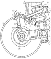
本明細書で説明した本発明の多くの修正形態および他の実施形態は、前述の説明および添付の図面に示されている教示の恩恵を受ける本発明に関連している当業者なら企図できるであろう。したがって、本発明は、特定の開示された実施形態に限定されるものではなく、また修正形態および他の実施形態は添付の特許請求の範囲内に含まれるものであると理解されるべきである。例えば、図18は、3本の軸を含むセミレバー式着陸装置の代替実施形態を示している。セミレバー式着陸装置のいくつかの構成要素は、上述の構造、相互接続および機能と同じであるが、図18のセミレバー式着陸装置のいくつかの態様は修正されている。この点に関連して、第3のリンク24は緩衝支柱12に枢動可能に連結されているが、この実施形態の第3のリンクは、緩衝支柱の例えば外側シリンダ14に連結されたラグ60に枢動可能に連結される。後で言及するように、ラグ60は、第6のピボットピン38の上に配置され、トーションリンク20を緩衝支柱に枢動可能に連結する第4のピボットピン26から間隔を置いて配置される。さらに、図18の実施形態のトラックピッチアクチュエーションシステム40は、上述の実施形態では第3のピボットピン28と第5のピボットピン37の中間において第1のロックリンクに連結されているのとは対照的に、第5のピボットポイント37で一対のロックリンクに枢動可能に連結される。さらに、セミレバー式着陸装置リンク機構のばね34のような付勢装置は、上述とは別の方法で配置される。すなわち、ばねは、第1のリンク30bの中間部分とトラックビーム18の前端18aに付いているラグとの間に延在する。このように、本明細書では特定の用語を用いているが、それらは一般的な説明の意味で用いており限定を目的とするものではない。
Many modifications and other embodiments of the invention described herein can be contemplated by those skilled in the art to which this invention pertains that benefit from the teachings set forth in the foregoing description and accompanying drawings. I will. Accordingly, it is to be understood that the invention is not limited to specific disclosed embodiments, and that modifications and other embodiments are included within the scope of the appended claims. . For example, FIG. 18 shows an alternative embodiment of a semi-lever landing gear that includes three axes. Some components of the semi-lever landing gear are the same as the structure, interconnections and functions described above, but some aspects of the semi-lever landing gear of FIG. 18 have been modified. In this regard, the
Claims (9)
内側シリンダおよび外側シリンダを有する緩衝支柱と、
前記緩衝支柱の前記内側シリンダに枢動可能に連結されるトラックビームと、
第1のピボットで前記トラックビームに連結される第1のリンクと、
第2のピボットで前記第1のリンクに連結される第2のリンクと、
第3のピボットで前記第2のリンクに連結され、第4のピボットで前記外側シリンダに連結される、第3のリンクと、
前記第3のピボットを第1の位置および第2の位置の一方に配置するように前記第3のピボットに動作可能に連結されるトラックピッチアクチュエーションシステムと、及び、
前記第1のリンクと前記第2のリンクの間に延在する少なくとも1つの付勢装置と
を備える、セミレバー式着陸装置。 A semi-lever landing gear,
A buffer post having an inner cylinder and an outer cylinder;
A track beam pivotally connected to the inner cylinder of the buffer post;
A first link coupled to the track beam by a first pivot;
A second link coupled to the first link by a second pivot;
A third link connected to the second link by a third pivot and connected to the outer cylinder by a fourth pivot;
A track pitch actuation system operably coupled to the third pivot to position the third pivot in one of a first position and a second position ; and
A semi-lever landing gear comprising: at least one biasing device extending between the first link and the second link .
緩衝支柱と前記トラックビームの間に動作可能に連結される複数のリンク、およびトラックピッチアクチュエーションシステムを備えるセミレバー式着陸装置機構を用意するステップであって、前記複数のリンクは第1のリンクと第2のリンクを備え、前記第1のリンクと前記第2のリンクの間に少なくとも1つの付勢装置が延在する、ステップと、
航空機が空中にある間、前記トラックピッチアクチュエーションシステムを離陸位置につかせることによって、前記トラックビームの後端に対して前記トラックビームの前端を引き上げ位置に配置するステップと、
航空機が空中にある間、前記着陸装置の引込みを容易にするように、前記トラックピッチアクチュエーションシステムを収容位置につかせることによって、前記トラックビームの前記後端に対して前記トラックビームの前記前端を引き下げ位置に配置するステップと
を含む、方法。 A method for positioning a track beam of an aircraft landing gear, comprising:
Providing a plurality of links operably coupled between a buffer strut and the track beam, and a semi-lever landing gear mechanism comprising a track pitch actuation system , the plurality of links being a first link; Comprising a second link, wherein at least one biasing device extends between the first link and the second link ;
Placing the front end of the track beam in a raised position relative to the rear end of the track beam by anchoring the track pitch actuation system to a take-off position while the aircraft is in the air;
The front end of the track beam is moved relative to the rear end of the track beam by forcing the track pitch actuation system to a stowed position to facilitate retracting of the landing gear while the aircraft is in the air. Placing in the retracted position.
Applications Claiming Priority (3)
| Application Number | Priority Date | Filing Date | Title |
|---|---|---|---|
| US12/730,598 | 2010-03-24 | ||
| US12/730,598 US8448900B2 (en) | 2010-03-24 | 2010-03-24 | Semi-levered landing gear and associated method |
| PCT/US2011/025966 WO2011119283A1 (en) | 2010-03-24 | 2011-02-23 | Semi-levered landing gear and associated method |
Publications (2)
| Publication Number | Publication Date |
|---|---|
| JP2013522120A JP2013522120A (en) | 2013-06-13 |
| JP5596218B2 true JP5596218B2 (en) | 2014-09-24 |
Family
ID=44278927
Family Applications (1)
| Application Number | Title | Priority Date | Filing Date |
|---|---|---|---|
| JP2013501270A Active JP5596218B2 (en) | 2010-03-24 | 2011-02-23 | Semi-lever landing gear and related method |
Country Status (10)
| Country | Link |
|---|---|
| US (3) | US8448900B2 (en) |
| EP (1) | EP2550198B1 (en) |
| JP (1) | JP5596218B2 (en) |
| KR (1) | KR101895081B1 (en) |
| CN (1) | CN102822053B (en) |
| AU (1) | AU2011229883B2 (en) |
| CA (1) | CA2793734C (en) |
| ES (1) | ES2692373T3 (en) |
| RU (1) | RU2564277C2 (en) |
| WO (1) | WO2011119283A1 (en) |
Families Citing this family (44)
| Publication number | Priority date | Publication date | Assignee | Title |
|---|---|---|---|---|
| US8448900B2 (en) * | 2010-03-24 | 2013-05-28 | The Boeing Company | Semi-levered landing gear and associated method |
| US9481452B2 (en) | 2010-11-22 | 2016-11-01 | The Boeing Company | Hydraulic actuator for semi levered landing gear |
| US8939400B2 (en) | 2011-02-21 | 2015-01-27 | The Boeing Company | Air-ground detection system for semi-levered landing gear |
| US8998133B2 (en) | 2011-04-01 | 2015-04-07 | The Boeing Company | Landing gear system |
| GB2489058B (en) * | 2011-08-22 | 2013-05-08 | Messier Dowty Ltd | Aircraft landing gear |
| GB2494219B (en) * | 2012-02-06 | 2013-10-16 | Messier Dowty Ltd | A fairing |
| US8752785B2 (en) * | 2012-06-25 | 2014-06-17 | Bell Helicopter Textron Inc. | Semi-levered articulated landing gear system |
| KR200467824Y1 (en) * | 2013-02-21 | 2013-07-05 | (주) 코마코 | Landing gear lever for aircraft |
| GB2518605B (en) * | 2013-09-18 | 2020-02-12 | Airbus Operations Ltd | Drive system for landing gear |
| US9090342B2 (en) * | 2013-10-04 | 2015-07-28 | Goodrich Corporation | Rocking bogie mechanism |
| US9321524B2 (en) * | 2014-04-22 | 2016-04-26 | Goodrich Corporation | Bogie beam articulation mechanism |
| CN104149972A (en) * | 2014-07-02 | 2014-11-19 | 张更生 | Method capable of adjusting plane undercarriage |
| EP3135581B1 (en) * | 2015-08-25 | 2018-03-21 | Safran Landing Systems UK Limited | Aircraft landing gear assembly |
| US9868521B2 (en) * | 2016-01-14 | 2018-01-16 | Embraer S.A. | Retractable self-aligning aircraft stablizer strut assembly and aircraft including the same |
| EP3213992B1 (en) * | 2016-03-04 | 2018-04-25 | Safran Landing Systems UK Limited | Aircraft landing gear assembly |
| US10351227B2 (en) | 2016-07-29 | 2019-07-16 | Goodrich Corporation | Electrically powered downlock actuation system |
| US10086928B2 (en) * | 2016-07-29 | 2018-10-02 | Goodrich Corporation | Electrically powered downlock actuation system |
| US10293920B2 (en) | 2016-09-02 | 2019-05-21 | The Boeing Company | Landing gear toggle lock mechanism |
| US10562614B2 (en) | 2016-09-21 | 2020-02-18 | The Boeing Company | Aircraft landing gear, aircraft, and related methods |
| DK3568378T3 (en) | 2017-01-13 | 2022-01-17 | Momentive Performance Mat Inc | FOLDED QUARTZ CONTAINER WHICH HAS LOW LEVELS OF SURFACE DEFECTS |
| US10384767B2 (en) | 2017-01-25 | 2019-08-20 | The Boeing Company | Single axle, semi-levered landing gear with shortening mechanism |
| US10766608B2 (en) * | 2017-02-28 | 2020-09-08 | The Boeing Company | Aircraft landing gear having a retract actuator, aircraft including the same, and related methods |
| US10669017B2 (en) * | 2017-02-28 | 2020-06-02 | The Boeing Company | Aircraft landing gear, aircraft, and related methods |
| US10597146B2 (en) * | 2017-02-28 | 2020-03-24 | The Boeing Company | Aircraft landing gear having a lever assembly, aircraft including the same, and related methods |
| US10625849B2 (en) * | 2017-04-11 | 2020-04-21 | The Boeing Company | Levered landing gear with inner shock strut |
| US10486798B2 (en) | 2017-04-18 | 2019-11-26 | The Boeing Company | Aircraft landing gear assembly and method of assembling the same |
| ES2906230T3 (en) | 2017-04-20 | 2022-04-13 | Safran Landing Systems Uk Ltd | aircraft landing gear assembly |
| US10800516B2 (en) * | 2017-06-02 | 2020-10-13 | The Boeing Company | Semi-levered shrink landing gear |
| BR102018008986B1 (en) * | 2017-06-23 | 2023-12-26 | Goodrich Corporation | LANDING GEAR ARRANGEMENT, AND, METHOD FOR EXTENDING A LANDING GEAR ARRANGEMENT FOR AN AIRPLANE |
| GB2563946A (en) * | 2017-06-30 | 2019-01-02 | Airbus Operations Ltd | Pitch trimmer |
| FR3072943B1 (en) * | 2017-10-27 | 2021-12-10 | Safran Landing Systems | AIRCRAFT LANDING WITH BRAKED WHEELS AND MOTORIZED WHEELS |
| KR20190060620A (en) | 2017-11-24 | 2019-06-03 | 대우조선해양 주식회사 | Apparatus for avoiding fishing net of submarine |
| CN107914867B (en) * | 2017-12-06 | 2023-10-27 | 南京航空航天大学 | Friction locking self-adaptive deformation landing gear and control method thereof |
| US11161599B2 (en) | 2018-01-26 | 2021-11-02 | The Boeing Company | Landing gear strut assembly and method therefor |
| US10577128B2 (en) * | 2018-03-30 | 2020-03-03 | The Boeing Company | Health monitoring of aircraft landing gear mechanical structures |
| US11008091B2 (en) | 2018-05-03 | 2021-05-18 | The Boeing Company | Body mounted shrinking landing gear |
| FR3082825B1 (en) * | 2018-06-26 | 2020-09-04 | Safran Landing Systems | WHEEL ACTUATOR LOCKING MECHANISM |
| US10981646B2 (en) | 2018-07-30 | 2021-04-20 | The Boeing Company | Landing gear shrink link mechanism |
| US11433994B2 (en) * | 2019-07-17 | 2022-09-06 | The Boeing Company | Mechanical link with preload verification |
| US10793262B1 (en) | 2019-07-17 | 2020-10-06 | The Boeing Company | Mechanical link with preload verification |
| US10583919B1 (en) | 2019-07-17 | 2020-03-10 | The Boeing Company | Mechanical link with preload verification |
| US11091252B2 (en) | 2019-07-30 | 2021-08-17 | Safran Landing Systems Canada Inc. | Aircraft multi-wheel truck beam positioner |
| JP7256761B2 (en) * | 2020-01-09 | 2023-04-12 | 川崎重工業株式会社 | lifting system |
| US20240140597A1 (en) * | 2022-10-26 | 2024-05-02 | Safran Landing Systems Canada Inc. | Landing gear main fitting with integral shock absorber |
Family Cites Families (27)
| Publication number | Priority date | Publication date | Assignee | Title |
|---|---|---|---|---|
| US3083937A (en) * | 1959-02-05 | 1963-04-02 | English Electric Co Ltd | Aeroplane undercarriages |
| SU133348A1 (en) * | 1960-01-15 | 1960-11-30 | В.В. Кириллин | The mechanism of rotation of the truck landing gear |
| GB1006522A (en) * | 1963-10-08 | 1965-10-06 | Electro Hydraulics Ltd | Retractable undercarriages for aircraft |
| US3345019A (en) * | 1965-12-30 | 1967-10-03 | Bendix Corp | Aircraft landing gear |
| US4359199A (en) * | 1979-12-05 | 1982-11-16 | The United States Of America As Represented By The Secretary Of The Air Force | Soft landing gear |
| GB2101542A (en) | 1981-06-13 | 1983-01-19 | British Aerospace | Aircraft undercarriage unit |
| FR2598676B1 (en) * | 1986-05-13 | 1988-07-29 | Messier Hispano Sa | AIRCRAFT LANDER WITH TIPPING BEAM AND REDUCED SIZE |
| FR2616410B1 (en) | 1987-06-09 | 1992-08-21 | Messier Hispano Sa | TIPPING BEAM LANDING DEVICE |
| FR2625969B1 (en) * | 1988-01-15 | 1990-07-06 | Aerospatiale | DEVICE FOR INCREASING THE STABILITY OF ON-BOARD AND LANDING HELICOPTERS, WITH TRICYCLE LANDING GEAR, AND HELICOPTER EQUIPPED WITH SUCH A DEVICE |
| GB8803134D0 (en) * | 1988-02-11 | 1988-03-09 | British Aerospace | Aircraft undercarriage unit |
| US5086995A (en) * | 1990-04-09 | 1992-02-11 | The Boeing Company | Aft cantilevered wing landing gear for heavy airplane with aft center of gravity |
| GB9223714D0 (en) * | 1992-11-12 | 1992-12-23 | British Aerospace | Auxiliary control of aircraft landing gear movement |
| FR2699886B1 (en) * | 1992-12-28 | 1995-03-24 | Messier Bugatti | Liftable undercarriage, especially for large aircraft. |
| RU2088478C1 (en) * | 1995-02-28 | 1997-08-27 | Акционерное общество открытого типа "ОКБ Сухого" | Flying vehicle retractable landing gear |
| US6308916B1 (en) * | 1998-03-19 | 2001-10-30 | The B. F. Goodrich Company | Dual mode positioner for an aircraft landing gear axle beam |
| US6182925B1 (en) * | 1999-03-30 | 2001-02-06 | The Boeing Company | Semi-levered landing gear and auxiliary strut therefor |
| US6575405B2 (en) * | 1999-03-30 | 2003-06-10 | The Boeing Company | Control system and method for a semi-levered landing gear for an aircraft |
| US8136759B2 (en) * | 2004-06-18 | 2012-03-20 | Goodrich Corporation | Retractable articulated landing gear |
| US7066429B2 (en) * | 2004-06-25 | 2006-06-27 | The Boeing Company | Apparatus and method for predictable movement of structural components during failure |
| WO2006094145A1 (en) | 2005-03-02 | 2006-09-08 | Goodrich Corporation | Landing gear with articulated length extension mechanism |
| DE102005027385B4 (en) | 2005-06-14 | 2011-08-18 | Airbus Operations GmbH, 21129 | Method and device for supporting the star rotation of an aircraft |
| GB2428650B (en) | 2005-08-04 | 2011-01-12 | Messier Dowty Ltd | Landing gear |
| US7578466B2 (en) * | 2006-01-06 | 2009-08-25 | The Boeing Company | Mechanism for reducing heat generation in a joint |
| CA2659293C (en) * | 2006-08-08 | 2014-03-18 | Loadhog Limited | Transporting loads |
| GB2453554B (en) * | 2007-10-09 | 2012-03-14 | Messier Dowty Ltd | Load detection in an aircraft landing gear |
| EP2340996B1 (en) * | 2009-12-30 | 2012-02-08 | AGUSTAWESTLAND S.p.A. | Retractable helicopter landing gear |
| US8448900B2 (en) * | 2010-03-24 | 2013-05-28 | The Boeing Company | Semi-levered landing gear and associated method |
-
2010
- 2010-03-24 US US12/730,598 patent/US8448900B2/en active Active
-
2011
- 2011-02-23 RU RU2012144766/11A patent/RU2564277C2/en active
- 2011-02-23 CA CA2793734A patent/CA2793734C/en active Active
- 2011-02-23 KR KR1020127021625A patent/KR101895081B1/en active IP Right Grant
- 2011-02-23 JP JP2013501270A patent/JP5596218B2/en active Active
- 2011-02-23 EP EP11707030.0A patent/EP2550198B1/en active Active
- 2011-02-23 CN CN201180015380.0A patent/CN102822053B/en active Active
- 2011-02-23 WO PCT/US2011/025966 patent/WO2011119283A1/en active Application Filing
- 2011-02-23 ES ES11707030.0T patent/ES2692373T3/en active Active
- 2011-02-23 AU AU2011229883A patent/AU2011229883B2/en active Active
-
2013
- 2013-05-22 US US13/900,071 patent/US8991753B2/en active Active
- 2013-05-22 US US13/900,098 patent/US8985511B2/en active Active
Also Published As
| Publication number | Publication date |
|---|---|
| EP2550198B1 (en) | 2018-07-25 |
| WO2011119283A1 (en) | 2011-09-29 |
| ES2692373T3 (en) | 2018-12-03 |
| CN102822053A (en) | 2012-12-12 |
| AU2011229883A1 (en) | 2012-08-23 |
| US8448900B2 (en) | 2013-05-28 |
| CA2793734A1 (en) | 2011-09-29 |
| US20130256455A1 (en) | 2013-10-03 |
| AU2011229883B2 (en) | 2016-08-04 |
| US8985511B2 (en) | 2015-03-24 |
| KR20130006599A (en) | 2013-01-17 |
| RU2012144766A (en) | 2014-04-27 |
| CN102822053B (en) | 2015-08-05 |
| US20110233327A1 (en) | 2011-09-29 |
| EP2550198A1 (en) | 2013-01-30 |
| CA2793734C (en) | 2015-09-08 |
| JP2013522120A (en) | 2013-06-13 |
| KR101895081B1 (en) | 2018-09-04 |
| RU2564277C2 (en) | 2015-09-27 |
| US8991753B2 (en) | 2015-03-31 |
| US20140151499A1 (en) | 2014-06-05 |
Similar Documents
| Publication | Publication Date | Title |
|---|---|---|
| JP5596218B2 (en) | Semi-lever landing gear and related method | |
| EP3354564B1 (en) | Single axle, semi-levered landing gear with shortening mechanism | |
| EP3647187B1 (en) | Landing gear | |
| US9205917B2 (en) | Vertically retracting side articulating landing gear for aircraft | |
| CN106477027B (en) | Three-position aircraft tail sled mechanism and actuation method | |
| EP3093237A1 (en) | Method of operating a hydraulic actuator for semi levered landing gear | |
| US20120168561A1 (en) | Fuselage mounted landing gear | |
| US20170158315A1 (en) | System and method for spring assisted landing gear operation | |
| US6360990B1 (en) | Landing gear | |
| US20150069178A1 (en) | Fuselage-mounted landing gear assembly for use with a low wing aircraft | |
| EP1129939A2 (en) | Rotary door assembly for landing gear | |
| US11427309B2 (en) | Hinged truck assembly for aircraft landing gear | |
| EP3681796B1 (en) | Folding landing gear | |
| US6349901B1 (en) | Landing gear | |
| CN218463869U (en) | Unmanned vehicles undercarriage and hatch door linkage jack | |
| GB2621885A (en) | Articulated landing gear shield | |
| CN114368474A (en) | Undercarriage cabin door sequential retraction linkage mechanism and linkage method |
Legal Events
| Date | Code | Title | Description |
|---|---|---|---|
| A977 | Report on retrieval |
Free format text: JAPANESE INTERMEDIATE CODE: A971007 Effective date: 20131227 |
|
| A131 | Notification of reasons for refusal |
Free format text: JAPANESE INTERMEDIATE CODE: A131 Effective date: 20140107 |
|
| A601 | Written request for extension of time |
Free format text: JAPANESE INTERMEDIATE CODE: A601 Effective date: 20140403 |
|
| A602 | Written permission of extension of time |
Free format text: JAPANESE INTERMEDIATE CODE: A602 Effective date: 20140410 |
|
| A521 | Request for written amendment filed |
Free format text: JAPANESE INTERMEDIATE CODE: A523 Effective date: 20140502 |
|
| TRDD | Decision of grant or rejection written | ||
| A01 | Written decision to grant a patent or to grant a registration (utility model) |
Free format text: JAPANESE INTERMEDIATE CODE: A01 Effective date: 20140708 |
|
| A61 | First payment of annual fees (during grant procedure) |
Free format text: JAPANESE INTERMEDIATE CODE: A61 Effective date: 20140806 |
|
| R150 | Certificate of patent or registration of utility model |
Ref document number: 5596218 Country of ref document: JP Free format text: JAPANESE INTERMEDIATE CODE: R150 |
|
| R250 | Receipt of annual fees |
Free format text: JAPANESE INTERMEDIATE CODE: R250 |
|
| R250 | Receipt of annual fees |
Free format text: JAPANESE INTERMEDIATE CODE: R250 |
|
| R250 | Receipt of annual fees |
Free format text: JAPANESE INTERMEDIATE CODE: R250 |
|
| R250 | Receipt of annual fees |
Free format text: JAPANESE INTERMEDIATE CODE: R250 |
|
| R250 | Receipt of annual fees |
Free format text: JAPANESE INTERMEDIATE CODE: R250 |
|
| R250 | Receipt of annual fees |
Free format text: JAPANESE INTERMEDIATE CODE: R250 |
|
| R250 | Receipt of annual fees |
Free format text: JAPANESE INTERMEDIATE CODE: R250 |
|
| R250 | Receipt of annual fees |
Free format text: JAPANESE INTERMEDIATE CODE: R250 |