RU2352852C2 - In-place curing lining material with external impermeable layer, and manufacturing method thereof - Google Patents
In-place curing lining material with external impermeable layer, and manufacturing method thereof Download PDFInfo
- Publication number
- RU2352852C2 RU2352852C2 RU2006119930/06A RU2006119930A RU2352852C2 RU 2352852 C2 RU2352852 C2 RU 2352852C2 RU 2006119930/06 A RU2006119930/06 A RU 2006119930/06A RU 2006119930 A RU2006119930 A RU 2006119930A RU 2352852 C2 RU2352852 C2 RU 2352852C2
- Authority
- RU
- Russia
- Prior art keywords
- tubular element
- resin
- layer
- impregnated
- impermeable
- Prior art date
Links
Images
Classifications
-
- B—PERFORMING OPERATIONS; TRANSPORTING
- B29—WORKING OF PLASTICS; WORKING OF SUBSTANCES IN A PLASTIC STATE IN GENERAL
- B29D—PRODUCING PARTICULAR ARTICLES FROM PLASTICS OR FROM SUBSTANCES IN A PLASTIC STATE
- B29D23/00—Producing tubular articles
- B29D23/001—Pipes; Pipe joints
-
- F—MECHANICAL ENGINEERING; LIGHTING; HEATING; WEAPONS; BLASTING
- F16—ENGINEERING ELEMENTS AND UNITS; GENERAL MEASURES FOR PRODUCING AND MAINTAINING EFFECTIVE FUNCTIONING OF MACHINES OR INSTALLATIONS; THERMAL INSULATION IN GENERAL
- F16L—PIPES; JOINTS OR FITTINGS FOR PIPES; SUPPORTS FOR PIPES, CABLES OR PROTECTIVE TUBING; MEANS FOR THERMAL INSULATION IN GENERAL
- F16L55/00—Devices or appurtenances for use in, or in connection with, pipes or pipe systems
- F16L55/16—Devices for covering leaks in pipes or hoses, e.g. hose-menders
-
- B—PERFORMING OPERATIONS; TRANSPORTING
- B29—WORKING OF PLASTICS; WORKING OF SUBSTANCES IN A PLASTIC STATE IN GENERAL
- B29C—SHAPING OR JOINING OF PLASTICS; SHAPING OF MATERIAL IN A PLASTIC STATE, NOT OTHERWISE PROVIDED FOR; AFTER-TREATMENT OF THE SHAPED PRODUCTS, e.g. REPAIRING
- B29C53/00—Shaping by bending, folding, twisting, straightening or flattening; Apparatus therefor
- B29C53/36—Bending and joining, e.g. for making hollow articles
- B29C53/38—Bending and joining, e.g. for making hollow articles by bending sheets or strips at right angles to the longitudinal axis of the article being formed and joining the edges
- B29C53/48—Bending and joining, e.g. for making hollow articles by bending sheets or strips at right angles to the longitudinal axis of the article being formed and joining the edges for articles of indefinite length, i.e. bending a strip progressively
- B29C53/50—Bending and joining, e.g. for making hollow articles by bending sheets or strips at right angles to the longitudinal axis of the article being formed and joining the edges for articles of indefinite length, i.e. bending a strip progressively using internal forming surfaces, e.g. mandrels
-
- B—PERFORMING OPERATIONS; TRANSPORTING
- B29—WORKING OF PLASTICS; WORKING OF SUBSTANCES IN A PLASTIC STATE IN GENERAL
- B29C—SHAPING OR JOINING OF PLASTICS; SHAPING OF MATERIAL IN A PLASTIC STATE, NOT OTHERWISE PROVIDED FOR; AFTER-TREATMENT OF THE SHAPED PRODUCTS, e.g. REPAIRING
- B29C65/00—Joining or sealing of preformed parts, e.g. welding of plastics materials; Apparatus therefor
- B29C65/48—Joining or sealing of preformed parts, e.g. welding of plastics materials; Apparatus therefor using adhesives, i.e. using supplementary joining material; solvent bonding
- B29C65/50—Joining or sealing of preformed parts, e.g. welding of plastics materials; Apparatus therefor using adhesives, i.e. using supplementary joining material; solvent bonding using adhesive tape, e.g. thermoplastic tape; using threads or the like
- B29C65/5092—Joining or sealing of preformed parts, e.g. welding of plastics materials; Apparatus therefor using adhesives, i.e. using supplementary joining material; solvent bonding using adhesive tape, e.g. thermoplastic tape; using threads or the like characterised by the tape handling mechanisms, e.g. using vacuum
-
- B—PERFORMING OPERATIONS; TRANSPORTING
- B29—WORKING OF PLASTICS; WORKING OF SUBSTANCES IN A PLASTIC STATE IN GENERAL
- B29C—SHAPING OR JOINING OF PLASTICS; SHAPING OF MATERIAL IN A PLASTIC STATE, NOT OTHERWISE PROVIDED FOR; AFTER-TREATMENT OF THE SHAPED PRODUCTS, e.g. REPAIRING
- B29C66/00—General aspects of processes or apparatus for joining preformed parts
- B29C66/70—General aspects of processes or apparatus for joining preformed parts characterised by the composition, physical properties or the structure of the material of the parts to be joined; Joining with non-plastics material
- B29C66/72—General aspects of processes or apparatus for joining preformed parts characterised by the composition, physical properties or the structure of the material of the parts to be joined; Joining with non-plastics material characterised by the structure of the material of the parts to be joined
- B29C66/723—General aspects of processes or apparatus for joining preformed parts characterised by the composition, physical properties or the structure of the material of the parts to be joined; Joining with non-plastics material characterised by the structure of the material of the parts to be joined being multi-layered
- B29C66/7234—General aspects of processes or apparatus for joining preformed parts characterised by the composition, physical properties or the structure of the material of the parts to be joined; Joining with non-plastics material characterised by the structure of the material of the parts to be joined being multi-layered comprising a barrier layer
-
- B—PERFORMING OPERATIONS; TRANSPORTING
- B29—WORKING OF PLASTICS; WORKING OF SUBSTANCES IN A PLASTIC STATE IN GENERAL
- B29C—SHAPING OR JOINING OF PLASTICS; SHAPING OF MATERIAL IN A PLASTIC STATE, NOT OTHERWISE PROVIDED FOR; AFTER-TREATMENT OF THE SHAPED PRODUCTS, e.g. REPAIRING
- B29C66/00—General aspects of processes or apparatus for joining preformed parts
- B29C66/80—General aspects of machine operations or constructions and parts thereof
- B29C66/83—General aspects of machine operations or constructions and parts thereof characterised by the movement of the joining or pressing tools
- B29C66/836—Moving relative to and tangentially to the parts to be joined, e.g. transversely to the displacement of the parts to be joined, e.g. using a X-Y table
-
- F—MECHANICAL ENGINEERING; LIGHTING; HEATING; WEAPONS; BLASTING
- F16—ENGINEERING ELEMENTS AND UNITS; GENERAL MEASURES FOR PRODUCING AND MAINTAINING EFFECTIVE FUNCTIONING OF MACHINES OR INSTALLATIONS; THERMAL INSULATION IN GENERAL
- F16L—PIPES; JOINTS OR FITTINGS FOR PIPES; SUPPORTS FOR PIPES, CABLES OR PROTECTIVE TUBING; MEANS FOR THERMAL INSULATION IN GENERAL
- F16L55/00—Devices or appurtenances for use in, or in connection with, pipes or pipe systems
- F16L55/16—Devices for covering leaks in pipes or hoses, e.g. hose-menders
- F16L55/162—Devices for covering leaks in pipes or hoses, e.g. hose-menders from inside the pipe
- F16L55/165—Devices for covering leaks in pipes or hoses, e.g. hose-menders from inside the pipe a pipe or flexible liner being inserted in the damaged section
- F16L55/1652—Devices for covering leaks in pipes or hoses, e.g. hose-menders from inside the pipe a pipe or flexible liner being inserted in the damaged section the flexible liner being pulled into the damaged section
- F16L55/1654—Devices for covering leaks in pipes or hoses, e.g. hose-menders from inside the pipe a pipe or flexible liner being inserted in the damaged section the flexible liner being pulled into the damaged section and being inflated
-
- F—MECHANICAL ENGINEERING; LIGHTING; HEATING; WEAPONS; BLASTING
- F16—ENGINEERING ELEMENTS AND UNITS; GENERAL MEASURES FOR PRODUCING AND MAINTAINING EFFECTIVE FUNCTIONING OF MACHINES OR INSTALLATIONS; THERMAL INSULATION IN GENERAL
- F16L—PIPES; JOINTS OR FITTINGS FOR PIPES; SUPPORTS FOR PIPES, CABLES OR PROTECTIVE TUBING; MEANS FOR THERMAL INSULATION IN GENERAL
- F16L55/00—Devices or appurtenances for use in, or in connection with, pipes or pipe systems
- F16L55/16—Devices for covering leaks in pipes or hoses, e.g. hose-menders
- F16L55/162—Devices for covering leaks in pipes or hoses, e.g. hose-menders from inside the pipe
- F16L55/165—Devices for covering leaks in pipes or hoses, e.g. hose-menders from inside the pipe a pipe or flexible liner being inserted in the damaged section
- F16L55/1656—Devices for covering leaks in pipes or hoses, e.g. hose-menders from inside the pipe a pipe or flexible liner being inserted in the damaged section materials for flexible liners
-
- B—PERFORMING OPERATIONS; TRANSPORTING
- B29—WORKING OF PLASTICS; WORKING OF SUBSTANCES IN A PLASTIC STATE IN GENERAL
- B29C—SHAPING OR JOINING OF PLASTICS; SHAPING OF MATERIAL IN A PLASTIC STATE, NOT OTHERWISE PROVIDED FOR; AFTER-TREATMENT OF THE SHAPED PRODUCTS, e.g. REPAIRING
- B29C65/00—Joining or sealing of preformed parts, e.g. welding of plastics materials; Apparatus therefor
- B29C65/48—Joining or sealing of preformed parts, e.g. welding of plastics materials; Apparatus therefor using adhesives, i.e. using supplementary joining material; solvent bonding
- B29C65/50—Joining or sealing of preformed parts, e.g. welding of plastics materials; Apparatus therefor using adhesives, i.e. using supplementary joining material; solvent bonding using adhesive tape, e.g. thermoplastic tape; using threads or the like
- B29C65/5042—Joining or sealing of preformed parts, e.g. welding of plastics materials; Apparatus therefor using adhesives, i.e. using supplementary joining material; solvent bonding using adhesive tape, e.g. thermoplastic tape; using threads or the like covering both elements to be joined
-
- B—PERFORMING OPERATIONS; TRANSPORTING
- B29—WORKING OF PLASTICS; WORKING OF SUBSTANCES IN A PLASTIC STATE IN GENERAL
- B29C—SHAPING OR JOINING OF PLASTICS; SHAPING OF MATERIAL IN A PLASTIC STATE, NOT OTHERWISE PROVIDED FOR; AFTER-TREATMENT OF THE SHAPED PRODUCTS, e.g. REPAIRING
- B29C65/00—Joining or sealing of preformed parts, e.g. welding of plastics materials; Apparatus therefor
- B29C65/56—Joining or sealing of preformed parts, e.g. welding of plastics materials; Apparatus therefor using mechanical means or mechanical connections, e.g. form-fits
- B29C65/62—Stitching
-
- B—PERFORMING OPERATIONS; TRANSPORTING
- B29—WORKING OF PLASTICS; WORKING OF SUBSTANCES IN A PLASTIC STATE IN GENERAL
- B29C—SHAPING OR JOINING OF PLASTICS; SHAPING OF MATERIAL IN A PLASTIC STATE, NOT OTHERWISE PROVIDED FOR; AFTER-TREATMENT OF THE SHAPED PRODUCTS, e.g. REPAIRING
- B29C66/00—General aspects of processes or apparatus for joining preformed parts
- B29C66/01—General aspects dealing with the joint area or with the area to be joined
- B29C66/05—Particular design of joint configurations
- B29C66/10—Particular design of joint configurations particular design of the joint cross-sections
- B29C66/11—Joint cross-sections comprising a single joint-segment, i.e. one of the parts to be joined comprising a single joint-segment in the joint cross-section
- B29C66/114—Single butt joints
- B29C66/1142—Single butt to butt joints
-
- B—PERFORMING OPERATIONS; TRANSPORTING
- B29—WORKING OF PLASTICS; WORKING OF SUBSTANCES IN A PLASTIC STATE IN GENERAL
- B29C—SHAPING OR JOINING OF PLASTICS; SHAPING OF MATERIAL IN A PLASTIC STATE, NOT OTHERWISE PROVIDED FOR; AFTER-TREATMENT OF THE SHAPED PRODUCTS, e.g. REPAIRING
- B29C66/00—General aspects of processes or apparatus for joining preformed parts
- B29C66/01—General aspects dealing with the joint area or with the area to be joined
- B29C66/05—Particular design of joint configurations
- B29C66/10—Particular design of joint configurations particular design of the joint cross-sections
- B29C66/13—Single flanged joints; Fin-type joints; Single hem joints; Edge joints; Interpenetrating fingered joints; Other specific particular designs of joint cross-sections not provided for in groups B29C66/11 - B29C66/12
- B29C66/133—Fin-type joints, the parts to be joined being flexible
-
- B—PERFORMING OPERATIONS; TRANSPORTING
- B29—WORKING OF PLASTICS; WORKING OF SUBSTANCES IN A PLASTIC STATE IN GENERAL
- B29C—SHAPING OR JOINING OF PLASTICS; SHAPING OF MATERIAL IN A PLASTIC STATE, NOT OTHERWISE PROVIDED FOR; AFTER-TREATMENT OF THE SHAPED PRODUCTS, e.g. REPAIRING
- B29C66/00—General aspects of processes or apparatus for joining preformed parts
- B29C66/40—General aspects of joining substantially flat articles, e.g. plates, sheets or web-like materials; Making flat seams in tubular or hollow articles; Joining single elements to substantially flat surfaces
- B29C66/41—Joining substantially flat articles ; Making flat seams in tubular or hollow articles
- B29C66/43—Joining a relatively small portion of the surface of said articles
- B29C66/432—Joining a relatively small portion of the surface of said articles for making tubular articles or closed loops, e.g. by joining several sheets ; for making hollow articles or hollow preforms
- B29C66/4322—Joining a relatively small portion of the surface of said articles for making tubular articles or closed loops, e.g. by joining several sheets ; for making hollow articles or hollow preforms by joining a single sheet to itself
-
- B—PERFORMING OPERATIONS; TRANSPORTING
- B29—WORKING OF PLASTICS; WORKING OF SUBSTANCES IN A PLASTIC STATE IN GENERAL
- B29C—SHAPING OR JOINING OF PLASTICS; SHAPING OF MATERIAL IN A PLASTIC STATE, NOT OTHERWISE PROVIDED FOR; AFTER-TREATMENT OF THE SHAPED PRODUCTS, e.g. REPAIRING
- B29C66/00—General aspects of processes or apparatus for joining preformed parts
- B29C66/70—General aspects of processes or apparatus for joining preformed parts characterised by the composition, physical properties or the structure of the material of the parts to be joined; Joining with non-plastics material
- B29C66/71—General aspects of processes or apparatus for joining preformed parts characterised by the composition, physical properties or the structure of the material of the parts to be joined; Joining with non-plastics material characterised by the composition of the plastics material of the parts to be joined
-
- B—PERFORMING OPERATIONS; TRANSPORTING
- B29—WORKING OF PLASTICS; WORKING OF SUBSTANCES IN A PLASTIC STATE IN GENERAL
- B29C—SHAPING OR JOINING OF PLASTICS; SHAPING OF MATERIAL IN A PLASTIC STATE, NOT OTHERWISE PROVIDED FOR; AFTER-TREATMENT OF THE SHAPED PRODUCTS, e.g. REPAIRING
- B29C67/00—Shaping techniques not covered by groups B29C39/00 - B29C65/00, B29C70/00 or B29C73/00
- B29C67/0014—Shaping techniques not covered by groups B29C39/00 - B29C65/00, B29C70/00 or B29C73/00 for shaping tubes or blown tubular films
- B29C67/0018—Turning tubes inside out
-
- B—PERFORMING OPERATIONS; TRANSPORTING
- B29—WORKING OF PLASTICS; WORKING OF SUBSTANCES IN A PLASTIC STATE IN GENERAL
- B29L—INDEXING SCHEME ASSOCIATED WITH SUBCLASS B29C, RELATING TO PARTICULAR ARTICLES
- B29L2023/00—Tubular articles
- B29L2023/005—Hoses, i.e. flexible
- B29L2023/006—Flexible liners
-
- Y—GENERAL TAGGING OF NEW TECHNOLOGICAL DEVELOPMENTS; GENERAL TAGGING OF CROSS-SECTIONAL TECHNOLOGIES SPANNING OVER SEVERAL SECTIONS OF THE IPC; TECHNICAL SUBJECTS COVERED BY FORMER USPC CROSS-REFERENCE ART COLLECTIONS [XRACs] AND DIGESTS
- Y10—TECHNICAL SUBJECTS COVERED BY FORMER USPC
- Y10T—TECHNICAL SUBJECTS COVERED BY FORMER US CLASSIFICATION
- Y10T156/00—Adhesive bonding and miscellaneous chemical manufacture
- Y10T156/10—Methods of surface bonding and/or assembly therefor
- Y10T156/1002—Methods of surface bonding and/or assembly therefor with permanent bending or reshaping or surface deformation of self sustaining lamina
- Y10T156/1007—Running or continuous length work
- Y10T156/1008—Longitudinal bending
- Y10T156/1013—Longitudinal bending and edge-joining of one piece blank to form tube
Landscapes
- Engineering & Computer Science (AREA)
- Mechanical Engineering (AREA)
- General Engineering & Computer Science (AREA)
- Lining Or Joining Of Plastics Or The Like (AREA)
- Pipe Accessories (AREA)
- Extrusion Moulding Of Plastics Or The Like (AREA)
- Laminated Bodies (AREA)
Abstract
Description
Область техники, к которой относится изобретениеFIELD OF THE INVENTION
Настоящее изобретение относится к отверждаемому на месте облицовочному материалу для бестраншейной реконструкции существующих водоводов и трубопроводов и, более конкретно, к пропитанному смолой отверждаемому на месте облицовочному материалу с вывернутым наизнанку внешним непроницаемым покрытием или защитной изоляцией, которые непрерывно формируются по длине материала, подходящему для бестраншейной реконструкции существующих трубопроводов, используя втягивание и накачивание.The present invention relates to an in situ curable facing material for trenchless reconstruction of existing water conduits and pipelines, and more particularly, to a resin impregnated in situ curable facing material with an inside-out outer impermeable coating or protective insulation that are continuously formed along the length of the material suitable for trenchless reconstruction existing pipelines using retraction and inflation.
Уровень техникиState of the art
Общеизвестно, что существующие водоводы и трубопроводы, особенно подземные трубопроводы, такие как системы канализации для коммунально-бытовых вод, коллекторы ливневой канализации, водоводы и газовые линии, которые применяются для отвода текучих сред, часто необходимо ремонтировать из-за утечки текучей среды. Эта утечка может быть направлена внутрь из окружающей среды во внутреннюю часть или проводящую часть трубопроводов. В качестве альтернативы утечка может быть направлена наружу из проводящей части трубопровода в окружающую среду. В любом случае просачивания или эксфильтрации желательно избегать утечек такого типа.It is well known that existing water conduits and pipelines, especially underground pipelines, such as sewage systems for municipal water, storm sewers, water conduits and gas lines that are used to divert fluids, often need to be repaired due to fluid leakage. This leak may be directed inward from the environment into the interior or conductive portion of the piping. Alternatively, the leak may be directed outward from the conductive portion of the pipeline into the environment. In any case, leakage or exfiltration, it is desirable to avoid this type of leakage.
Утечка в имеющихся трубопроводах может быть вызвана несовершенным размещением исходного трубопровода или повреждением самой трубы вследствие обычного старения, или действием транспортируемых коррозионных или абразивных материалов. Трещины на соединениях труб или вблизи них могут быть вызваны условиями окружающей среды, такими как землетрясения или движение крупных транспортных средств на надземной поверхности, или аналогичными естественными или искусственными колебаниями, или другими причинами. Независимо от причины такие утечки являются нежелательными и могут привести к выбросу текучей среды, транспортируемой внутри трубопровода, или привести к повреждению окружающей среды и, возможно, к созданию опасности для системы здравоохранения. В случае длительной утечки она может привести к нарушению структуры имеющихся трубопроводов вследствие потери почвы и боковой опоры трубопровода.Leakage in existing pipelines can be caused by imperfect placement of the original pipeline or damage to the pipe itself due to normal aging, or the action of transported corrosive or abrasive materials. Cracks at or near pipe joints can be caused by environmental conditions, such as earthquakes or the movement of large vehicles on an elevated surface, or by similar natural or artificial vibrations, or other causes. Regardless of the cause, such leaks are undesirable and can result in the release of fluid transported inside the pipeline, or damage the environment and possibly endanger the health system. In the event of prolonged leakage, it can lead to disruption of the structure of existing pipelines due to soil loss and lateral support of the pipeline.
Вследствие постоянно возрастающих затрат на рабочую силу и машинное оборудование становится все более затруднительным и менее экономичным ремонтировать подземные трубопроводы или их участки, которые могут давать утечку, посредством выкапывания имеющихся труб и их замены на новые трубы. В результате были разработаны различные способы ремонта или реконструкции существующих трубопроводов на месте установки. В этих новых способах устраняются затраты и опасности, связанные с выкапыванием и заменой труб или звеньев трубопровода, а также значительные неудобства для людей в процессе ремонтных работ. Одним из наиболее эффективных способов ремонта или бестраншейной реконструкции трубопроводов, который широко распространен в настоящее время, называется Insituform® Process. Этот процесс Insituform Process подробно описан в патентах US 4009063, US 4064211 и US 4135958, все содержание которых включено в это изобретение как ссылка.Due to the ever-increasing costs of labor and machinery, it is becoming increasingly difficult and less economical to repair underground pipelines or parts of them that can leak by digging out existing pipes and replacing them with new pipes. As a result, various methods have been developed for repair or reconstruction of existing pipelines at the installation site. These new methods eliminate the costs and dangers associated with digging and replacing pipes or pipe links, as well as significant inconvenience to people in the repair process. One of the most effective ways to repair or trenchless pipeline reconstruction, which is widely used today, is called the Insituform® Process. This Insituform Process is described in detail in US Pat. Nos. 4,090,663, 4,064,211 and 4,135,958, all of which are incorporated herein by reference.
Согласно установившейся практике способа Insituform Process удлиненная гибкая цилиндрическая облицовка из нетканого материала, пены или аналогичного материала, который может быть пропитан смолой, с внешним непроницаемым покрытием, пропитанным термореактивной отверждаемой смолой, монтируется внутри трубопровода. В наиболее широко распространенном варианте выполнения этого способа облицовка устанавливается посредством процесса выворачивания, который описан в патентах US 4064211 и US 4135958 Insituform. В процессе выворачивания радиальное давление, прилагаемое к внутренней части вывернутой наизнанку облицовки, прижимает ее к (и приводит в контакт с) внутренней поверхности трубопровода, когда облицовка развертывается по длине трубопровода. Кроме того, способ Insituform Process осуществляется путем вытягивания пропитанной смолой облицовки внутрь трубопровода посредством троса или каната с использованием отдельного, непроницаемого для текучей среды накачиваемого эластичного баллона или трубки, которая вывернута наизнанку внутрь облицовки, вызывая отверждение облицовки на внутренней стенке трубопровода. Такую пропитанную смолой облицовку обычно называют "отверждаемым на месте трубопроводом" или "CIPP облицовкой", а такое размещение называется монтажом CIPP.According to the established practice of the Insituform Process method, an elongated flexible cylindrical lining of non-woven material, foam or a similar material that can be impregnated with a resin, with an external impermeable coating impregnated with a thermosetting cured resin, is mounted inside the pipeline. In the most widespread embodiment of this method, the liner is installed by the eversion process, which is described in US Pat. No. 4,064,211 and US Pat. No. 4,135,958 by Insituform. During inversion, the radial pressure applied to the inside of the liner turned inside out presses it against (and makes contact with) the inner surface of the pipeline when the liner unfolds along the length of the pipeline. In addition, the Insituform Process method is carried out by pulling the resin-impregnated liner into the pipeline by means of a cable or rope using a separate, fluid-tight inflatable elastic balloon or tube that is turned inside out inside the liner, causing the liner to cure on the inner wall of the pipeline. Such a resin-impregnated cladding is commonly referred to as an “in-place curable conduit” or “CIPP cladding”, and this arrangement is called CIPP mounting.
Традиционные отверждаемые на месте гибкие трубчатые облицовочные материалы для размещения посредством выворачивания, а также втягивания и накачивания CIPP имеют внешний гладкий слой относительно гибкого, практически непроницаемого полимерного покрытия в исходном состоянии. Внешнее покрытие обеспечивает проникновение смолы во внутренний слой материала, который может быть пропитан смолой, такой как войлок. Будучи вывернутым наизнанку, этот непроницаемый слой оканчивается на внутренней облицовке с пропитанным смолой слоем напротив стенки существующего трубопровода. Когда гибкая облицовка монтируется на месте, внутри трубопровода, внутри этого трубопровода создается давление, предпочтительно посредством выворачивающей текучей среды, такой как вода или воздух, радиально воздействуя на облицовку снаружи для того, чтобы привести в контакт и соответствие с внутренней частью поверхности трубопровода. Отверждение смолы инициируется посредством введения отверждающей горячей текучей среды, такой как вода, внутрь вывернутой наизнанку облицовки через рециркуляционный рукав, подсоединенный к концу вывернутой облицовки. Затем отверждают смолу, пропитывающую материал изнутри, получая твердую трубную облицовку с плотной посадкой внутри трубопровода. Эта новая облицовка эффективно уплотняет любые трещины и ремонтирует повреждение любого звена трубопровода или трубного соединения для того, чтобы предотвратить дальнейшую утечку или внутрь, или наружу из трубопровода. Кроме того, отвержденная смола предназначена для укрепления стенки существующего трубопровода, и, таким образом, обеспечивается дополнительная конструкционная поддержка для охраны окружающей среды.Conventional in situ curable flexible tubular cladding materials for placement by turning as well as retracting and inflating CIPP have an outer smooth layer of a relatively flexible, practically impermeable polymer coating in its original state. The outer coating allows the resin to penetrate into the inner layer of the material, which may be impregnated with a resin, such as felt. Being turned inside out, this impermeable layer terminates on the inner lining with a resin-impregnated layer opposite the wall of the existing pipeline. When the flexible liner is mounted in place, inside the pipeline, pressure is created inside the pipeline, preferably by eversion fluid, such as water or air, acting radially on the liner from the outside in order to bring into contact and conformity with the interior of the surface of the pipeline. Curing of the resin is initiated by introducing a curing hot fluid, such as water, into the inside of the facing through the recirculation sleeve connected to the end of the turned facing. The resin impregnating the material from the inside is then cured to form a solid pipe lining with a snug fit inside the pipeline. This new cladding effectively seals any cracks and repairs damage to any link in the pipeline or pipe connection in order to prevent further leakage either in or out of the pipeline. In addition, the cured resin is intended to strengthen the wall of the existing pipeline, and thus provides additional structural support for environmental protection.
Когда трубчатые отверждаемые на месте облицовочные материалы монтируются способом втягивания и накачивания, облицовка пропитывается смолой таким же образом, как в процессе выворачивания, и втягивается и размещается внутри трубопровода в сплющенном состоянии. При типичном размещении нисходящая труба, накачиваемая труба или трубопровод, имеющий коленчатый патрубок в нижнем конце, размещается внутри имеющегося люка или в месте доступа, и вывернутый эластичный баллон пропускают через нисходящую трубу, раскрытую и отвернутую назад, поверх входной части горизонтального участка коленчатого патрубка, и вставляют в сплющенную облицовку. Затем сплющенную облицовку внутри трубопровода располагают и прикрепляют к отвернутому назад концу накачиваемого эластичного баллона. Затем в нисходящую трубу подают выворачивающую текучую среду, такую как вода, и давление воды побуждает вытеснение накачиваемого эластичного баллона из горизонтального участка коленчатого патрубка и вызывает расширение сплющенной облицовки относительно внутренней части поверхности трубопровода. Разворачивание накачиваемого эластичного баллона продолжается, пока этот эластичный баллон не достигнет (и не расширится до) находящегося ниже люка или второго места доступа. В этот момент дают отвердиться облицовке, прижимающейся к внутренней части поверхности трубопровода. Отверждение инициируется посредством введения горячей отверждающей воды, введенной внутрь накачиваемого эластичного баллона, в основном, таким же образом, как рециркуляционная линия, соединенная с концом вывернутого эластичного баллона, чтобы вызвать отверждение смолы в пропитанном слое.When tubular in situ curable liners are mounted by pulling and inflating, the liner is impregnated with resin in the same way as it is turned out, and it is drawn and placed inside the pipeline in a flattened state. In a typical arrangement, a descending pipe, an inflated pipe or pipe having a bent pipe at the lower end is placed inside an existing hatch or access point, and an inverted elastic balloon is passed through a descending pipe opened and bent back over the inlet of the horizontal portion of the crank pipe, and inserted into a tapered lining. Then, the flattened lining inside the pipeline is positioned and attached to the back-turned end of the inflated elastic balloon. Then, an eversible fluid such as water is supplied to the descending pipe, and the pressure of the water causes the inflated elastic balloon to be forced out of the horizontal portion of the elbow and causes the tapered lining to expand relative to the inside of the pipe surface. The deployment of the inflated elastic balloon continues until this elastic balloon reaches (and expands to) the lower hatch or second access point. At this moment, the liner is cured, pressing against the inside of the surface of the pipeline. Curing is initiated by introducing hot curing water introduced into the inflated elastic balloon, essentially in the same way as a recirculation line connected to the end of the inverted elastic balloon to cause the resin to solidify in the impregnated layer.
После отверждения смолы в облицовке накачиваемый эластичный баллон может быть удален или оставлен на месте установки в отвержденной облицовке. Обычно для способа втягивания и накачивания, а также для способа выворачивания требуется доступ оператора для того, чтобы ограничить пространство люка в отдельных случаях в ходе процесса. Например, доступ оператора требуется для закрепления вывернутой облицовки или баллона на конце коленчатого патрубка и вставки ее в сплющенную облицовку.After the resin has cured in the liner, the inflated elastic balloon can be removed or left at the installation site in the cured liner. Typically, the retraction and inflation method, as well as the eversion method, require operator access in order to limit the hatch space in some cases during the process. For example, operator access is required to secure an inverted liner or balloon at the end of an elbow and insert it into a flattened liner.
Независимо от того, как будет смонтирована облицовка, поглощающие слои облицовки пропитываются отверждаемой термореактивной смолой посредством способа, который называется "смачивание". Обычно способ смачивания включает введение смолы в слои, поглощающие смолу через край или отверстие, образовавшееся во внешней непроницаемой пленке, откачку в вакууме и пропускание пропитанной облицовки между прижимными роликами, как хорошо известно в уровне техники облицовки. Могут быть использованы самые различные смолы, такие как полиэфирные, сложные виниловые эфиры, эпоксидные смолы и им подобные, которые могут быть модифицированы, по желанию. Предпочтительно применяются смолы, которые относительно стабильны при комнатной температуре, но которые легко отверждаются при обработке горячим воздухом, паром или водой или подвергаются действию соответствующего облучения, такого как ультрафиолетовое излучение.Regardless of how the cladding will be mounted, the absorbent layers of the cladding are impregnated with a curable thermosetting resin through a method called wetting. Typically, a wetting method involves introducing the resin into layers absorbing the resin through an edge or hole formed in the outer impermeable film, pumping in a vacuum, and passing the impregnated lining between the pressure rollers, as is well known in the lining art. A wide variety of resins can be used, such as polyester, vinyl esters, epoxy resins and the like, which can be modified as desired. Resins that are relatively stable at room temperature but which cure easily when treated with hot air, steam or water, or are exposed to the appropriate radiation, such as ultraviolet radiation, are preferably used.
Одна такая методика смачивания облицовки посредством вакуумной пропитки описана в патенте Insituform US 4366012. Когда облицовка имеет внутренние и внешние непроницаемые слои, трубчатая облицовка может быть снабжена фасками и прорезями, сформованными на противоположных сторонах сплюснутой облицовки, причем смола вводится на обе стороны, как описано в патенте US 4009063. Другое устройство для смачивания в процессе монтажа при откачивании в вакууме на заднем конце облицовки продемонстрировано в патенте US 4182262. Содержание каждого из этих патентов включено в изобретение как ссылка.One such technique for wetting a liner by vacuum impregnation is described in Insituform US Pat. No. 4,366,012. When the liner has inner and outer impermeable layers, the tubular liner may be chamfered and slit molded on opposite sides of the oblate liner, with resin being introduced on both sides as described in US patent 4009063. Another device for wetting during installation during pumping in vacuum at the rear end of the cladding is shown in US patent 4182262. The contents of each of these patents include in EHO herein by reference.
Недавно были предприняты усилия для того, чтобы модифицировать способ втягивания и накачивания, используя воздух для выворачивания эластичного баллона внутрь растянутой облицовки из ближайшего места доступа. Когда вывернутый эластичный баллон достигает наиболее удаленного места доступа, в ближайшее место доступа вводится водяной пар для того, чтобы инициировать отверждение смолы, которой пропитан соответствующий слой. Этот способ обеспечивает преимущество ускоренного отверждения под действием повышенной энергии пара, введенного в качестве отверждающей текучей среды. Однако в этом способе все же требуется выворачивание эластичного баллона внутрь растянутой пропитанной облицовки. С целью устранения этой стадии выворачивания эластичного баллона внутрь растянутой облицовки стадию выворачивания осуществляют на земле. Например, в патенте US 6270289, этот способ включает выворачивание калиброванного рукава в лежащий плоско на земле облицованный рукав до вытягивания рукавного блока в существующий трубопровод. В этом способе исключена стадия выворачивания под землей, но способ существенно ограничен по длине облицовки, которая может быть разложена на земле до вытягивания.Efforts have recently been made to modify the retract and inflate method using air to twist the elastic balloon into the stretched liner from the closest access point. When the inverted elastic balloon reaches the farthest access point, water vapor is introduced into the nearest access point in order to initiate the curing of the resin to which the corresponding layer has been impregnated. This method provides the advantage of accelerated curing under the action of increased energy of steam introduced as a curing fluid. However, in this method, it is still necessary to twist the elastic balloon inside the stretched impregnated lining. In order to eliminate this stage of eversion of the elastic balloon inside the stretched lining, the eversion stage is carried out on the ground. For example, in US Pat. No. 6,270,289, this method involves twisting a calibrated sleeve into a lined sleeve lying flat on the ground before pulling the sleeve unit into an existing pipeline. In this method, the stage of eversion under the ground is excluded, but the method is significantly limited by the length of the lining, which can be decomposed on the ground before stretching.
Кроме того, с целью исключения этой стадии выворачивания предлагается производить облицовку, имеющую внутреннее покрытие и внешнее покрытие для того, чтобы отверждающую текучую среду можно было вводить непосредственно внутрь растянутой облицовки. Недостатки способа включают затруднения, возникающие при попытке пропитать смолой материал, который расположен между внутренним и внешним непроницаемым покрытием. Внешнее покрытие является существенным для манипулирования пропитанной облицовкой и для обеспечения втягивания облицовки в трубопровод, а внутреннее покрытие является предпочтительным для отверждения всей смолы паром.In addition, in order to avoid this eversion stage, it is proposed to produce a lining having an inner coating and an outer coating so that the curing fluid can be introduced directly into the stretched lining. The disadvantages of the method include the difficulties encountered when trying to impregnate a resin material, which is located between the inner and outer impermeable coating. An outer coating is essential for handling the impregnated liner and for allowing the liner to be drawn into the conduit, and an inner coating is preferred for curing the entire resin with steam.
Независимо от последних усовершенствований в способах бестраншейной реконструкции с использованием методов выворачивания, а также втягивания и накачивания, в обоих способах требуются большие затраты, связанные с интенсивной работой и наличием стадии выворачивания. Поэтому желательно разработать облицовку, произведенную с внутренним и внешним непроницаемым покрытием, которые могут быть легко пропитаны, с обеспечением отверждения паром в качестве отверждающей текучей среды, используя энергию для обеспечения способа монтажа, который является ускоренным и более эффективным экономически, чем современные способы реконструкции.Regardless of recent improvements in trenchless reconstruction methods using eversion methods, as well as retraction and pumping, both methods require high costs associated with intensive work and the presence of an eversion stage. Therefore, it is desirable to develop a liner made with an internal and external impermeable coating that can be easily impregnated, providing steam curing as a curing fluid, using energy to provide an installation method that is faster and more cost-effective than modern reconstruction methods.
Раскрытие изобретенияDisclosure of invention
В сущности, согласно изобретению разработан облицовочный материал, пропитанный отверждаемой на месте смолой, с внутренней трубкой из материала, который может быть пропитан смолой, и вывернутое наизнанку внешнее непроницаемое покрытие, предназначенное для реконструкции существующих трубопроводов, используя втягивание и накачивание. Эта облицовка может иметь внутренний непроницаемый слой, который непрерывно формируется по длине материала, поглощающего смолу и связанный с его поверхностью непроницаемый слой, образовавшийся во внутреннем трубчатом элементе и герметизированный с непроницаемым слоем на внутренней стороне трубки. В качестве альтернативы трубка из пропитываемого смолой материала может быть сформована вокруг непрерывной трубки непроницаемого слоя. Затем пропитываемая смолой трубка может быть обернута дополнительными слоями пропитанного смолой материала, закрепленного внутри трубчатой формы, пропитанной термореактивной смолой и обернутой внешним покрытием, непроницаемым для смолы и герметизированным. Внешнее непроницаемое покрытие или защитная изоляция наносится на трубку посредством выворачивания трубки из непроницаемого материала на внутреннем трубчатом элементе, когда он поступает в трубчатую обкладочную машину. Внешнее покрытие выполнено в виде предварительно сформованной трубки или непрерывно формуемой и герметизируемой до выворачивания наизнанку поверх внутреннего трубчатого элемента.Essentially, according to the invention, a liner material impregnated with an in situ curable resin is developed with an inner tube of a material that can be impregnated with a resin, and an external impermeable coating turned inside out, intended for reconstructing existing pipelines using retraction and pumping. This lining may have an inner impermeable layer that is continuously formed along the length of the resin absorbing material and an impermeable layer connected to its surface formed in the inner tubular element and sealed with an impermeable layer on the inner side of the tube. Alternatively, a tube of resin impregnated material may be formed around a continuous tube of an impermeable layer. The resin-impregnated tube may then be wrapped with additional layers of resin-impregnated material fixed inside a tubular shape impregnated with a thermosetting resin and wrapped in an outer coating, resin-impermeable and sealed. An external impermeable coating or protective insulation is applied to the tube by turning the tube out of the impermeable material on the inner tubular member when it enters the tubular wrapping machine. The outer coating is made in the form of a preformed tube or continuously molded and sealed until inside out over the inner tubular element.
Соответственно, задачей изобретения является разработка усовершенствованного способа реконструкции существующих трубопроводов с отверждением на месте.Accordingly, an object of the invention is the development of an improved method for the reconstruction of existing pipelines with curing in place.
Другой задачей изобретения является разработка усовершенствованного облицовочного материала для реконструкции существующих трубопроводов с отверждением на месте.Another objective of the invention is the development of an improved facing material for the reconstruction of existing pipelines with curing in place.
Задачей изобретения является также разработка усовершенствованной облицовки из пропитанного смолой материала, имеющей внутренний непроницаемый слой и внешний непроницаемый слой, который вывернут наизнанку поверх пропитанной смолой внутренней трубки, который предназначен для бестраншейной реконструкции существующих трубопроводов.The objective of the invention is the development of an improved lining of resin-impregnated material having an inner impermeable layer and an outer impermeable layer that is turned inside out over the resin-impregnated inner tube, which is designed for trenchless reconstruction of existing pipelines.
Еще одной задачей изобретения является разработка усовершенствованного способа непрерывного получения пропитанного смолой отверждаемого на месте облицовочного материала, имеющего вывернутый наизнанку внешний непроницаемый слой.Another objective of the invention is the development of an improved method for the continuous production of resin-cured in situ curable facing material having an outer impermeable layer turned inside out.
Задачей изобретения является разработка способа получения пропитанного смолой отверждаемого на месте облицовочного материала, имеющего внутренний и внешний непроницаемые слои, для бестраншейного монтажа трубопровода путем втягивания и накачивания.The objective of the invention is to develop a method for producing a resin-cured in situ curable facing material having inner and outer impermeable layers for trenchless installation of a pipeline by drawing in and pumping.
Кроме того, другие цели и преимущества этого изобретения будут отчасти очевидными и будут отчасти явными из описания изобретения.In addition, other objects and advantages of this invention will be partly apparent and will be partly apparent from the description of the invention.
Соответственно, это изобретение содержит несколько этапов, причем связь одного или нескольких таких этапов относительно друг друга, устройства, в которых воплощены конструктивные признаки, сочетания и компоновка деталей, которые приспособлены для осуществления таких этапов, и продукты, которые обладают характеристиками, признаками, свойствами, и связь компонентов, примеры которых приведены в следующем подробном описании, и объем изобретения будут раскрыты в формуле изобретения.Accordingly, this invention comprises several steps, the connection of one or more of these steps relative to each other, devices that embody structural features, combinations and arrangement of parts that are adapted to carry out such steps, and products that have characteristics, features, properties, and the relationship of components, examples of which are given in the following detailed description, and the scope of the invention will be disclosed in the claims.
Краткое описание чертежейBrief Description of the Drawings
Изобретение поясняется посредством чертежей, на которых представлено:The invention is illustrated by means of the drawings, which show:
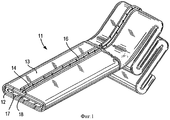
фиг.1 - общий вид отрезка типичного пропитываемого смолой, отверждаемого на месте облицовочного материала, предназначенного для применения при облицовке существующих трубопроводов, типа обычно используемых в настоящее время и известных из уровня техники;figure 1 - General view of a segment of a typical resin impregnated, cured in place of the facing material intended for use in facing existing pipelines, the type commonly used at present and known from the prior art;
фиг.2 - поперечное сечение отверждаемого на месте облицовочного материала, имеющего объединенный внутренний непроницаемый слой и внешнюю непроницаемую пленку или защитное покрытие, созданное и скомпонованное согласно изобретению;FIG. 2 is a cross-sectional view of an in situ curable facing material having a combined inner impermeable layer and an outer impermeable film or protective coating created and arranged according to the invention;
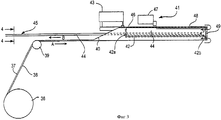
фиг.3 - схематичный чертеж устройства, используемого для получения внутренней части облицовки, имеющей внешний войлочный слой с внутренним высокотемпературным полимерным слоем, используемым при получении отверждаемого на месте облицовочного материала по фиг.2;figure 3 is a schematic drawing of a device used to obtain the inner part of the cladding having an outer felt layer with an inner high-temperature polymer layer used in the preparation of the in situ cured facing material of Fig. 2;
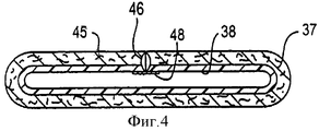
фиг.4 - поперечное сечение структуры внутренней части облицовки, полученной посредством устройства по фиг.3, до проведения пропитки согласно изобретению;figure 4 is a cross section of the structure of the inner part of the cladding obtained by the device of figure 3, before the impregnation according to the invention;
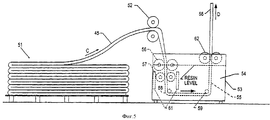
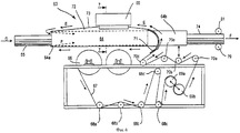
фиг.5 - схематичный вид в вертикальном разрезе, демонстрирующий пропитку смолой трубчатого элемента по фиг.4 для получения пропитанной CIPP облицовки согласно изобретению;Fig. 5 is a schematic vertical sectional view showing the resin impregnation of the tubular element of Fig. 4 to obtain a CIPP-impregnated lining according to the invention;
фиг.6 - схематичный вид в вертикальном разрезе, демонстрирующий герметизацию и нанесение обмотки на пропитанный трубчатый элемент, выходящий из резервуара со смолой по фиг.5, с внешним покрытием, с уплотнением кромки, расположенным внутри внешнего покрытия согласно изобретению;FIG. 6 is a schematic vertical sectional view illustrating sealing and winding of an impregnated tubular member exiting the resin reservoir of FIG. 5 with an outer coating, with an edge seal located inside the outer coating of the invention;
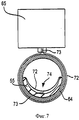
фиг.7 - поперечное сечение по линии 7-7 узла для сварки в устройстве герметизации и нанесения обмотки, по фиг.6;Fig.7 is a cross section along line 7-7 of the site for welding in a sealing device and applying a winding, Fig.6;
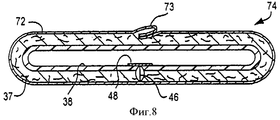
фиг.8 - поперечное сечение облицовки, изготовленной посредством устройства по фиг.6;Fig.8 is a cross section of a cladding made by the device of Fig.6;
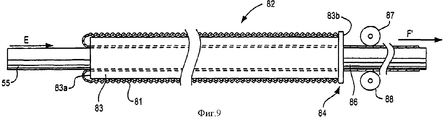
фиг.9 - схематичный вид в вертикальном разрезе нанесения обмотки на трубчатый элемент, выходящий из устройства пропитки смолой, с внешним покрытием, посредством пропускания смоченной облицовки через трубчатую обкладочную машину, имеющую заготовленное трубчатое защитное покрытие;Fig. 9 is a schematic vertical sectional view of applying a winding to a tubular member exiting from a resin impregnation device with an external coating by passing the wetted cladding through a tubular wrapping machine having a prepared tubular protective coating;
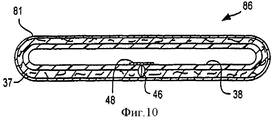
фиг.10 - поперечное сечение облицовки, обернутой посредством устройства по фиг.9.figure 10 is a cross section of the cladding wrapped by the device of figure 9.
Осуществление изобретенияThe implementation of the invention
Пропитанный смолой отверждаемый на месте облицовочный материал, полученный согласно предпочтительному варианту выполнения изобретения, имеет объединенную внутреннюю облицовку, так чтобы ее можно было вставить способом втягивания и накачивания и наполнить и отвердить нагретой текучей средой без использования накачиваемого эластичного баллона. Пропитанную облицовку желаемой длины с внутренним непроницаемым полимерным слоем получают непрерывно. Она может быть пропитана в собранном виде, с учетом необходимости дополнительных усилий для того, чтобы пропитать сплюснутую облицовку, содержащую между внутренним и внешним покрытием материал, поглощающий смолу, используя традиционную технологию вакуумной пропитки.The resin impregnated in place curable lining material obtained according to the preferred embodiment of the invention has an integrated inner lining so that it can be inserted by drawing in and pumping out and filling and curing with a heated fluid without using an inflated elastic balloon. An impregnated lining of the desired length with an inner impermeable polymer layer is produced continuously. It can be impregnated in assembled form, taking into account the need for additional efforts in order to impregnate a flattened cladding containing resin-absorbing material between the inner and outer coatings using traditional vacuum impregnation technology.
Эти дополнительные усилия действительно необходимы, как свидетельствует практика способа по патенту US 6270289. При этом калиброванный рукав выворачивается наизнанку на земле, образуя лежащий плоско рукав с пропитанной облицовкой, или рукав с пропитанной облицовкой посредством сжатого воздуха выворачивается наизнанку, образуя трубчатую пленку. В этом случае отрезок облицованного рукава приблизительно равен длине подземного трубопровода, подлежащего облицовке. Для выворачивания одной трубки внутри другой требуется свободное пространство, равное длине самого длинного слоя. Если эти два слоя не были предварительно пропитаны, то может возникнуть необходимость вводить смолу между слоями с обеих сторон плоско лежащих труб для того, чтобы обеспечить соответствующую степень пропитки. Пропитка облицованных труб представляет собой трудную и неэффективную операцию. Таким образом, не только ограничена длина, но также пропитка является чрезвычайно затруднительной.These additional efforts are really necessary, as evidenced by the practice of the method according to the patent US 6270289. In this case, the calibrated sleeve is turned inside out on the ground, forming a flat sleeve with an impregnated lining, or the sleeve with an impregnated lining is turned inside out by means of compressed air, forming a tubular film. In this case, the section of the lined sleeve is approximately equal to the length of the underground pipeline to be lined. To turn one tube inside another, free space equal to the length of the longest layer is required. If these two layers have not been pre-impregnated, it may be necessary to introduce resin between the layers on both sides of the flat-lying pipes in order to provide an appropriate degree of impregnation. Impregnation of lined pipes is a difficult and inefficient operation. Thus, not only is the length limited, but also the impregnation is extremely difficult.
На фиг.1 показан гибкий отверждаемый на месте облицовочный материал 11, обычно используемый в настоящее время и хорошо известный из уровня техники. Облицовочный материал 11 выполнен, по меньшей мере, из одного слоя гибкого материала, который может быть пропитан смолой, такого как войлочный слой 12, имеющий внешний слой 13 из непроницаемой полимерной пленки. Войлочный слой 12 и внешний полимерный слой 13 сшиваются вдоль линии стыка 14, образуя трубчатую облицовку. Совместимая термопластичная пленка в форме ленты или штампованного материала 16 помещается (или прессуется) сверху линии стыка 14 для обеспечения непроницаемости облицовки 11. В показанном на фиг.1 и применяемом во всем описании изобретения варианте выполнения облицовка 11 содержит внутреннюю трубку второго войлочного слоя 17, который также сшивается вдоль линии стыка 18, расположенной в таком месте трубки, которое отличается от положения линии стыка 14 во внешнем войлочном слое 12. Затем формируется внешний войлочный слой 12 с полимерным слоем 13 вокруг внутреннего войлочного слоя 17. После пропитки облицовочного материала 11 по всей длине его хранят в камере охлаждения для того, чтобы подавлять преждевременное отверждение смолы. Затем отрезают желаемый отрезок облицовочного материала 11 после втягивания его внутрь существующего трубопровода или отрезают до выворачивания наизнанку внутри существующего трубопровода.Figure 1 shows a flexible in situ
Облицовочный материал 11, показанный на фиг.1, непроницаем для воды и воздуха. Это позволяет использовать воздух или воду при выворачивании, как описано выше. Однако при монтаже посредством втягивания и надувания, согласно изобретению, необходимо, чтобы внешнее покрытие на облицовке было лишь достаточно непроницаемым для того, чтобы обеспечить легкость манипулирования и сохранение смолы и чтобы предотвратить повреждение облицовки, когда она втягивается внутрь существующего трубопровода.The lining
При более крупном диаметре облицовки могут быть использованы несколько слоев войлока или пропитываемого смолой материала. Войлочные слои 12 и 17 представляют собой естественные или синтетические гибкие материалы, поглощающие смолу, такие как полиэфирные, акриловые, полипропиленовые или неорганические волокна, такие как из стекла и углерода. В качестве альтернативы поглощающий смолу материал может представлять собой пену. Непроницаемой пленкой 13 может быть полиолефин, такой как полиэтилен или полипропилен, виниловый полимер, такой как поливинилхлорид, или полиуретан, которые хорошо известны из уровня техники. Для соединения материала в виде трубки могут быть использованы любые формы сшивания, соединения склеиванием или газопламенная сварка, или любые другие подходящие приемы. На начальной стадии монтажа для любой бестраншейной реконструкции проводят очистку и видеоосмотр существующего трубопровода.With a larger cladding diameter, several layers of felt or resin-impregnated material may be used. Felt layers 12 and 17 are natural or synthetic flexible materials that absorb resin, such as polyester, acrylic, polypropylene or inorganic fibers, such as glass and carbon. Alternatively, the resin absorbent material may be foam. The
На фиг.2 показано поперечное сечение отверждаемого на месте облицовочного материала 21 согласно изобретению. Облицовка 21 подобна традиционной облицовке 11, однако она содержит внутренний непроницаемый слой 22, в котором имеется тонкий войлок или связанный с ним слой 23, пропитываемый смолой. Внутренний войлочный слой 23 сшит вдоль продольных кромок, образуя линию стыка 24 за счет ряда строчек 26, и герметизирован лентой 27, нанесенной сверху строчек 26. Внешний войлочный слой 28 обернут вокруг внутреннего тонкого войлочного слоя 23, и ему придается форма трубки посредством строчек 29. Окончательно внешнему слою или защитному покрытию 31 придают форму трубки посредством уплотнения по кромке 32, и его непрерывно выворачивают наизнанку поверх внешнего войлочного слоя 28 таким образом, что уплотнение по кромке 32 капсулируется под внешним непроницаемым слоем 31, что будет описано ниже более подробно.Figure 2 shows a cross section of a cured in place of the facing material 21 according to the invention. The lining 21 is similar to the
При таком производстве облицовки отпадает необходимость выворачивания облицовки в ходе ее размещения или выворачивания накачиваемого эластичного баллона после втягивания облицовки внутрь существующего трубопровода. Таким образом, могут быть существенно сокращены затраты труда в процессе монтажа. Кроме того, это позволяет использовать нагретую отверждающую текучую среду, такую как пар, чтобы накачать облицовку и отвердить смолу. В таком случае все нагретые текучие среды вводятся внутрь облицовки под землей, что обеспечивает более безопасные условия труда.With such a production of cladding, there is no need to turn the cladding during its placement or to turn the inflated elastic balloon after pulling the cladding into the existing pipeline. Thus, labor costs during installation can be significantly reduced. In addition, this allows the use of a heated curing fluid, such as steam, to inflate the liner and harden the resin. In this case, all heated fluids are introduced into the cladding underground, which ensures safer working conditions.
Войлочные слои 23 и 28 могут быть пропитаны обычным способом с использованием вакуума. В качестве альтернативы войлочные слои 23 и 28 сначала пропитывают смолой и затем наносят внешний непроницаемый слой 31. При этом устраняются затруднения при пропитке окончательной облицовки, в которой войлочные слои расположены между внутренним и внешним пропитываемым слоем. В патенте US 4009063 (Eric Wood) предложено вводить смолу в войлочный слой посредством игл, вставленных с противоположных сторон полученной сплюснутой облицовки. Для этой операции требуется нарезка и наложение заплат на отверстия от игл во внешнем покрытии. Способ вакуумной пропитки, раскрытый в патенте US 4366012, может оказаться неподходящим, если вакуум не подводится с обеих сторон, так как внутреннее покрытие представляет собой барьер для течения смолы внутрь облицовки с внутренним и внешним покрытием. Для преодоления затруднений при пропитке облицовку 21 производят из бесконечных рулонов плоско покрытого и гладкого войлока и непрерывно пропитанного до нанесения внешнего защитного покрытия 31. Это может быть выполнено посредством способа, использующего устройства, показанные на фиг.3, 5, и 6, с образованием облицовки 74, как показано на фиг.8.Felt layers 23 and 28 can be impregnated in the usual way using vacuum. Alternatively, the felt layers 23 and 28 are first impregnated with resin and then an outer impermeable layer 31 is applied. This eliminates the difficulty in impregnating the final lining, in which the felt layers are located between the inner and outer impregnated layers. US Pat. No. 4,090,663 (Eric Wood) proposes to introduce the resin into the felt layer by means of needles inserted from opposite sides of the obtained oblate cladding. This operation requires cutting and patching of the holes from the needles in the outer coating. The vacuum impregnation method disclosed in US Pat. No. 4,366,012 may not be suitable if the vacuum is not applied from both sides, since the inner coating is a barrier for the resin to flow into the lining with an inner and outer coating. To overcome the difficulties in impregnation, the lining 21 is made of endless rolls of flat-coated and smooth felt and continuously impregnated until the external protective coating 31 is applied. This can be done by a method using the devices shown in FIGS. 3, 5, and 6 to form the
Хотя войлочным слоям 23 и 28 придают форму трубок посредством сшивания и/или скрепления лентой, подходящими являются любые традиционно известные способы формирования труб из войлочных или других пропитываемых смолой материалов. Например, трубы могут быть сформованы посредством различных клеев или связующих материалов, а также газопламенной сварки. Лента может быть нанесена на внутренний непроницаемый слой 22 посредством связующей полосы или посредством экструзии слоя полимерного материала для того, чтобы герметизировать стыковое соединение войлочного материала и отверстия, образовавшееся в процессе сшивания.Although the felt layers 23 and 28 are shaped into tubes by stitching and / or tape bonding, any conventionally known methods of forming tubes from felt or other resin-impregnated materials are suitable. For example, pipes can be molded using various adhesives or binders, as well as flame welding. The tape may be applied to the inner impermeable layer 22 by means of a tie strip or by extrusion of a layer of polymer material in order to seal the butt joint of the felt material and the hole formed during the crosslinking process.
На фиг.3 показан способ непрерывного формирования отрезка трубы или пропитываемого смолой материала с герметизированным внутренним непроницаемым слоем. Рулон покрытого войлока 36, имеющий войлок 37 по всей длине, с непроницаемым слоем 38 поступает сверху направляющего ролика 39 в плоской форме, причем покрытая сторона ролика 39 обращена в сторону устройства 41, формирующего трубу.Figure 3 shows a method for continuously forming a length of pipe or material impregnated with resin with a sealed inner impermeable layer. A roll of coated felt 36 having felt 37 along its entire length, with an
Устройство 41, формирующее трубку, содержит трубчатую опорную раму 42, имеющую ближайший конец 42а и наиболее удаленный конец 42b и устройство 40, деформирующее пленку, выполненное в виде отражателя. Сшивающее устройство 43, которое представляет собой швейную машину и машину для запечатывания липкой лентой, клеильный станок или устройство газопламенной сварки, монтируется выше опорной рамы 42. Войлок 37 с непроницаемым слоем 38, обращенным к ролику 39, поступает в направлении стрелки А к ближайшему концу устройства 41, формирующего трубу, где он отклоняется упомянутым отражателем, наматывается вокруг опорной рамы 42 и сшивается в трубу 44 вдоль линии стыка 46 с войлоком 37 на внутренней стороне и непроницаемым слоем 38 на внешней стороне. Затем трубу 44 пропускают в лентообмоточное устройство 47, в котором лента 48 накладывается сверху линии стыка 46, образуя непроницаемый трубчатый элемент 45, покрытый лентой.The
Затем труба 44 продолжает перемещаться вдоль трубчатой опорной рамы 42 к инвертерному кольцу 49 на наиболее удаленном конце 42b опорной рамы 42. Затем обернутую лентой трубу 45 выворачивают наизнанку внутрь трубчатой опорной рамы 42, при этом непроницаемый слой 38 расположен внутри трубы 45, когда ее извлекают из ближайшего конца 42а трубчатой опорной рамы 42 вдоль линии, обозначенной стрелкой В. В этом месте вывернутая наизнанку труба 45 имеет структуру, показанную в поперечном разрезе на фиг.4, с непроницаемым слоем 38 на внутренней стороне и войлочным слоем 37 на внешней стороне. Труба 45 после этого хранится для последующего использования, или она может быть подана прямо на стадию пропитки смолой, как показано на фиг.5, до окончательного обертывания изоляцией.The
Фиг.5 схематично иллюстрирует пропитку запаса 51 трубы 45, покрытой лентой. Здесь труба 45 вытягивается в направлении стрелки С посредством пары вытягивающих роликов 52 с каучуковым покрытием в открытый сверху резервуар со смолой 53, заполненный до заданного уровня отверждаемой термореактивной смолой 54, чтобы образовалась пропитанная или смоченная труба 55. Труба 45 проходит между первым и вторым рядом прижимных роликов 56 и 57 и вокруг первого направляющего ролика 58, поворачивающего трубу 45 в горизонтальном направлении, и второго направляющего ролика 59, поворачивающего трубу в вертикальном направлении. Кроме второго направляющего ролика 57 (или вместо него) может быть использован генератор звуковых волн 61. Этот генератор звуковых волн 61 улучшает проникновение смолы 54 внутрь войлочного слоя 37 трубы 45, когда она проходит через резервуар со смолой 53. После изменения направления движения вокруг второго направляющего ролика 59 пропитанная смолой труба 55 проходит между парой пневматических калиброванных роликов 62. Тогда, в этот момент времени, труба 55 проходит через узел покрытия и герметизации защитной пленкой, обобщенно обозначенный позицией 63, в направлении стрелки D.5 schematically illustrates the impregnation of
Узел обертывания и герметизации защитной пленкой 63, показанный на фиг.6, содержит трубный формирователь 64, имеющий впускное отверстие 64а и выходное отверстие 64b и узел сварки кромки 65, расположенный над средней секцией трубного формирователя 64. Рулон 66 материала 67 с непроницаемой для смолы пленкой, которым будет обернута пропитанная труба 55, поступает в трубный формирователь 64. Материал 67 с непроницаемой для смолы пленкой поступает из рулона 66 на ряд направляющих роликов 68а-е и протягивается парой приводных роликов 69а и 69b, когда пленка 67 поступает поверх роликов 70а-d в трубный формирователь 64. Дефлектор 71 у выходного отверстия 64b трубного формирователя 64 направляет пленку 67 вокруг трубного формирователя 64 до ее подачи внутрь узла сварки 65, чтобы образовалась пленка 67 в трубке 72 с уплотнением по кромке 73, выступающей из трубы наружу. Трубка 72 непроницаемого материала, передвигающаяся вдоль трубного формирователя 64, вытягивается в направлении, указанном стрелкой Е, к входному концу 64а трубного формирователя 64, после чего трубка 72 непрерывно выворачивается наизнанку во внутренней части трубного формирователя 64, попадая на пропитанную трубу 55, и вытягивается в противоположном направлении, показанном пунктирной стрелкой F.The protective film wrapping and sealing
В этот момент пропитанная труба 55, входящая в открытый резервуар со смолой 54, поступает в направлении стрелки D во входное отверстие 64а трубного формирователя 64 и обвертывается вывернутой пленочной трубкой 72. Когда пленочная трубка 72 вывернута наизнанку, уплотнение по кромке 73 расположено на внутренней стороне трубки 72, так что уплотнение по кромке 73 располагается между пропитанной трубой 55 и пленочной трубкой 72. Обернутая смоченная CIPP облицовка 74, включающая смоченную трубу 55 и вывернутую наизнанку пленочную трубку 72, вытягивается из выходного отверстия 64b трубного формирователя 64 посредством пары приводных роликов 79 и 81. В качестве альтернативы облицовка 74 может быть выведена посредством протяжного механизма или ведомой ленты транспортера и поступает на охлажденную платформу для хранения и перевозки к месту размещения.At this point, the impregnated
На фиг.7 показано поперечное сечение узла для сварки 65 и трубного формирователя 64 вдоль линии 7-7 на фиг.6. В узле для сварки 65 образуется уплотнение по кромке 73 в пленочной трубке 72, когда эта трубка 72 проходит сверху наружной стороны трубного формирователя 64. Когда трубка 72 вывернута наизнанку, тогда уплотнение по кромке 73 с внутренней стороны обертывает смоченную трубу 74, когда ее вытягивают из выходного отверстия 64b трубного формирователя 64. Внешняя непроницаемая пленка 72 может быть нанесена до или после смачивания. В случае, когда это выполнено до смачивания, труба 45, полученная, как показано на фиг.3, поступает непосредственно в блок трубного формирователя 64 на фиг.6, и образуется облицовка 74, приведенная в поперечном сечении на фиг.8.7 shows a cross section of the site for welding 65 and the tube former 64 along the line 7-7 in Fig.6. In the assembly for welding 65, a seal is formed at the
На фиг.9 обобщенно проиллюстрировано альтернативное устройство 82 для нанесения внешнего защитного покрытия из непроницаемой трубки 81 вокруг пропитанной трубы 55. Здесь труба 55 может быть пропитана таким же образом, как описано в связи с резервуаром 53 для смачивания на фиг.5, и затем труба 55 поступает в трубчатую обкладочную машину 83, имеющую входной конец 83а и выпускной конец 83b. Для идентичных элементов здесь используется такая же нумерация, как и для фиг.5.FIG. 9 summarizes an
Запас гибкой непроницаемой трубки 81 подается на внешнюю сторону поверхности трубчатой обкладочной машины 83, имеющей входной конец 83а и выпускной конец 83b. Пропитанная труба 55 после резервуара со смолой 53 поступает во входной конец 83а трубчатой обкладочной машины 83. Когда труба 55 поступает во входной конец 83а трубчатой обкладочной машины 83, непроницаемая трубка 81 вытягивается наружу из трубчатой обкладочной машины 83 и выворачивается наизнанку вокруг входного конца 83а вовнутрь трубчатой обкладочной машины 83, чтобы обернуть пропитанную трубу 55, когда она покидает выпускной конец 83b. При этом образуется завершенная облицовка 86, имеющая внутренний непроницаемый слой 38 и внешнее непроницаемое покрытие 81. Трубку 86 с внешним покрытием 81 выводят из выпускного конца 83b трубчатой обкладочной машины 83 посредством пары ведомых роликов 87 и 88 или другого вытягивающего устройства, такого как протяжный механизм или транспортер, в направлении стрелки F'. Когда в этом варианте воплощения применяется штампованная труба, на внешнем непроницаемом покрытии 81 отсутствует шов. Единственным ограничением при изготовлении трубки 86 этим способом является длина непроницаемой трубки 81, которая может быть помещена в трубчатую обкладочную машину 83. Установлено, что на трубчатой обкладочной машине длиной приблизительно 20 футов (6,1 м) может быть обжата непроницаемая труба длиной приблизительно 1000 футов (304,80 м). Более длинный отрезок может быть оснащен на более длинной трубчатой обкладочной машине.A supply of flexible
На фиг.10 изображено поперечное сечение облицовки 86, которая покидает трубчатую обкладочную машину 83. Облицовка 86 содержит внутренний трубчатый элемент из материала 37, поглощающего смолу и имеющего непроницаемое внутреннее покрытие 38, герметизированное лентой 48, как описано в связи с фиг.4. После выхода из трубчатой обкладочной машины 83 облицовка 86 включает внешнее трубчатое защитное покрытие 81. Принимая во внимание то, что трубчатое защитное покрытие 81 представляет собой предварительно штампованную трубку, на внешнем защитном покрытии 81 отсутствуют какие-либо швы в связи с фиг.6 и 8.Figure 10 shows a cross section of the lining 86, which leaves the
Будучи на месте размещения, обернутая пропитанная трубка 74 или 86, имеющая внутренний непроницаемый слой 38 и внешнее непроницаемое защитное покрытие 72 или 81, подготовлена для монтажа способом втягивания и накачивания. Этот способ полностью описан в патенте US 4009063, содержание которого введено в изобретение как ссылка. В случае монтажа способом втягивания и накачивания для наполнения облицовки не нужен отдельный выворачиваемый эластичный баллон благодаря наличию внутреннего непроницаемого слоя 38. В результате подбора соответствующих материалов для внутреннего непроницаемого слоя 38, таких как полипропилен, операции накачивания и отверждения могут быть выполнены посредством пара, введенного внутрь облицовки 74 или 86, сразу в положении существующего трубопровода.At the place of placement, the wrapped impregnated
Описанные в изобретении способы и устройства предоставляют удобные возможности для получения отверждаемого на месте облицовочного материала, имеющего как внутренний, так и внешний непроницаемые слои. Устройство для формирования и выворачивания трубки, которое представлено на фиг.3, обеспечивает легкий способ приготовления внутренней части готовой трубы с непроницаемым слоем на внутренней стороне трубы и внешним войлочным слоем. Если желательно, то дополнительные слои непокрытого войлока могут быть обернуты вокруг формованной внутренней трубы.The methods and devices described in the invention provide convenient opportunities for producing in situ curable facing material having both inner and outer impermeable layers. The device for forming and turning the tube, which is presented in figure 3, provides an easy way to prepare the inner part of the finished pipe with an impermeable layer on the inner side of the pipe and the outer felt layer. If desired, additional layers of uncoated felt may be wrapped around the molded inner tube.
Внутренний трубчатый элемент для CIPP облицовки, полученный в соответствии со способом, описанным в связи с фиг.3, может быть легко пропитан в открытом сверху резервуаре со смолой и обернут непроницаемым защитным покрытием, как описано в связи с устройством, показанным на фиг.6 или на фиг.9. Посредством непрерывного формирования внешнего защитного покрытия с уплотнением по кромке и непрерывного выворачивания трубки герметизированной пленки вокруг смоченной трубы, уплотнение инвертируется, обеспечивая изолированную смоченную трубу с гладкой внешней поверхностью, подготовленной для монтажа методом втягивания и накачивания. Аналогично посредством выворачивания трубки относительно внутренней трубы также получается гладкая внешняя поверхность трубопровода, которая будет облицована.The inner tubular element for the CIPP cladding obtained in accordance with the method described in connection with FIG. 3 can be easily impregnated in the resin reservoir open at the top and wrapped with an impermeable protective coating, as described in connection with the device shown in FIG. 6 or Fig.9. By continuously forming an outer protective coating with an edge seal and continuously turning the sealed film tube around the wetted pipe, the seal is inverted to provide an insulated wetted pipe with a smooth outer surface prepared for installation by pulling and pumping. Similarly, by twisting the tube relative to the inner pipe, a smooth outer surface of the pipe is also obtained, which will be lined.
Очевидно, что эффективно достигнуты поставленные задачи, среди тех, которые стали очевидны в свете предшествующего описания, и, поскольку при осуществлении указанного выше способа могут быть сделаны определенные изменения в описанном продукте и в конструкции (узлах), изложенных без отклонения от объема изобретения, предполагается, что все материалы, содержащиеся в приведенном выше описании и показанные в сопровождающих чертежах, должны истолковываться как иллюстративные, но не в аспекте ограничения.It is obvious that the set objectives are effectively achieved, among those that have become obvious in the light of the previous description, and since the implementation of the above method can be made certain changes in the described product and in the design (nodes) set forth without deviating from the scope of the invention, it is assumed that all materials contained in the above description and shown in the accompanying drawings are to be construed as illustrative, but not in the aspect of limitation.
Кроме того, очевидно, что следующие ниже притязания предназначаются для защиты всех родовых и специфических признаков описанного здесь изобретения и всех формулировок объема изобретения, которые по существу редакции могут быть отнесены к формуле изобретения.In addition, it is obvious that the following claims are intended to protect all generic and specific features of the invention described here and all wording of the scope of the invention, which essentially wording can be attributed to the claims.
Claims (13)
обеспечивают наличие первого трубчатого элемента, по меньшей мере, из одного слоя пропитываемого смолой материала;
обеспечивают наличие отрезка материала, имеющего, по меньшей мере, непроницаемый для смолы слой;
первый трубчатый элемент подают в первом направлении;
второй трубчатый элемент формируют из отрезка материала, имеющего непроницаемый для смолы слой;
второй трубчатый элемент подают во втором направлении, в направлении к первому трубчатому элементу;
продолжают подавать первый трубчатый элемент в полость второго трубчатого элемента;
выворачивают наизнанку второй трубчатый элемент для оборачивания первого трубчатого элемента из пропитываемого смолой материала;
формируют отверждаемый на месте облицовочный материал с внешним непроницаемым слоем, капсулирующим первый трубчатый элемент из пропитываемого смолой материала; и
вытягивают облицовочный материал первого трубчатого элемента из пропитываемого смолой материала и внешнего второго трубчатого элемента из непроницаемого для смолы материала в первом направлении.1. A method of manufacturing an in situ curable facing material with an external impermeable coating, in which:
providing a first tubular element of at least one layer of resin impregnated material;
providing a piece of material having at least a resin-impermeable layer;
the first tubular element is fed in a first direction;
the second tubular element is formed from a piece of material having a layer impervious to resin;
the second tubular element is supplied in a second direction, in the direction of the first tubular element;
continue to feed the first tubular element into the cavity of the second tubular element;
the second tubular element is turned inside out to wrap the first tubular element from a material impregnated with resin;
forming a cured in place facing material with an external impermeable layer encapsulating the first tubular element from the material impregnated with the resin; and
the facing material of the first tubular element is drawn from the resin impregnated material and the outer second tubular element from the resin impervious material in the first direction.
обеспечивают наличие, по меньшей мере, одного слоя в виде дополнительного отрезка пропитываемого смолой материала; подают дополнительный слой из пропитываемого смолой материала вокруг первого трубчатого элемента; сворачивают дополнительный слой из пропитываемого смолой материала в трубку, формуемую вокруг первого трубчатого элемента до выворачивания наизнанку второго трубчатого элемента поверх первого трубчатого элемента.2. The method according to claim 1, in which:
provide the presence of at least one layer in the form of an additional segment of the material impregnated with the resin; supplying an additional layer of resin impregnated material around the first tubular element; roll an additional layer of resin-impregnated material into a tube formed around the first tubular element until the second tubular element is turned inside out over the first tubular element.
обеспечивают наличие первого герметизированного трубчатого элемента, имеющего объединенный внутренний непроницаемый слой;
формируют внешний непроницаемый слой вокруг первого трубчатого элемента посредством непрерывного предоставления трубки из непроницаемого материала; и
выворачивают наизнанку трубку из непроницаемого материала для обертывания внутреннего трубчатого элемента в качестве внешнего слоя посредством пропускания внешнего слоя в противоположном направлении с образованием обернутой трубчатой облицовки с пропитываемым смолой материалом, капсулированным между внешним непроницаемым слоем и внутренним непроницаемым слоем.5. A method of manufacturing an in situ curable facing material having a combined inner impermeable layer and an outer impermeable layer turned inside out, in which:
providing a first sealed tubular member having a combined inner impermeable layer;
forming an outer impermeable layer around the first tubular element by continuously providing a tube of impermeable material; and
the tube of impermeable material is turned inside out to wrap the inner tubular element as an outer layer by passing the outer layer in the opposite direction to form a wrapped tubular lining with resin impregnated material encapsulated between the outer impermeable layer and the inner impermeable layer.
фиксатор, предназначенный для удерживания отрезка непроницаемого материала;
трубчатый профиль, имеющий открытый входной конец и открытый выпускной конец;
узел уплотнения, предназначенный для герметизации отрезка непроницаемого материала, с образованием трубки, вокруг удаленного конца трубчатого профиля и выворачивания наизнанку трубки непроницаемого материала внутри входного конца, чтобы обернуть внутренний трубчатый элемент;
втягивающее средство для вытягивания обернутого внутреннего трубчатого элемента, когда защитная изоляция выворачивается наизнанку вокруг входного конца трубчатого профиля.11. A device for wrapping a cured in place of the facing material turned inside out by an external impermeable tubular insulation, containing:
a retainer designed to hold a piece of impermeable material;
a tubular profile having an open inlet end and an open outlet end;
a sealing assembly for sealing a piece of impermeable material to form a tube around the distal end of the tubular profile and turning inside out the impermeable material inside the inlet end to wrap the inner tubular element;
retractor for pulling the wrapped inner tubular element when the protective insulation is turned inside out around the inlet end of the tubular profile.
Applications Claiming Priority (2)
| Application Number | Priority Date | Filing Date | Title |
|---|---|---|---|
| US10/704,501 US7857932B1 (en) | 2003-11-07 | 2003-11-07 | Cured in place liner with everted outer impermeable layer and method of manufacture |
| US10/704,501 | 2003-11-07 |
Publications (2)
| Publication Number | Publication Date |
|---|---|
| RU2006119930A RU2006119930A (en) | 2007-12-27 |
| RU2352852C2 true RU2352852C2 (en) | 2009-04-20 |
Family
ID=34590744
Family Applications (1)
| Application Number | Title | Priority Date | Filing Date |
|---|---|---|---|
| RU2006119930/06A RU2352852C2 (en) | 2003-11-07 | 2004-11-03 | In-place curing lining material with external impermeable layer, and manufacturing method thereof |
Country Status (17)
| Country | Link |
|---|---|
| US (2) | US7857932B1 (en) |
| EP (1) | EP1680618A1 (en) |
| JP (1) | JP4590413B2 (en) |
| KR (1) | KR101154085B1 (en) |
| CN (1) | CN100520146C (en) |
| AU (1) | AU2004288927B2 (en) |
| BR (1) | BRPI0416315A (en) |
| CA (1) | CA2544947C (en) |
| DE (1) | DE212004000053U1 (en) |
| DK (1) | DK200600126U3 (en) |
| IL (1) | IL175466A (en) |
| NO (1) | NO20062564L (en) |
| NZ (1) | NZ547458A (en) |
| PL (2) | PL116178U1 (en) |
| RU (1) | RU2352852C2 (en) |
| SG (1) | SG148166A1 (en) |
| WO (1) | WO2005047755A1 (en) |
Families Citing this family (19)
| Publication number | Priority date | Publication date | Assignee | Title |
|---|---|---|---|---|
| US7857932B1 (en) * | 2003-11-07 | 2010-12-28 | Ina Acquisition Corp. | Cured in place liner with everted outer impermeable layer and method of manufacture |
| US7238251B1 (en) * | 2003-11-07 | 2007-07-03 | Insituform (Netherlands) B.V. | Method of preparing cured in place liner using resin impregnation tower |
| US7670086B2 (en) * | 2005-11-23 | 2010-03-02 | Lmk Enterprises, Inc. | Method of repairing a manhole chimney using a stretchable sleeve |
| CN101626884B (en) * | 2007-01-18 | 2013-11-06 | 路博润高级材料公司 | Cured in place pipe liner |
| JP4902406B2 (en) * | 2007-03-30 | 2012-03-21 | タキロン株式会社 | Manufacturing method of pipe rehabilitation material |
| US8591695B2 (en) | 2008-03-14 | 2013-11-26 | Danny Warren | Method and composition for lining a pipe |
| US9724872B2 (en) * | 2009-05-27 | 2017-08-08 | Lmk Technologies, Llc | Apparatus and method for lining a pipe |
| CN101900239B (en) * | 2010-05-26 | 2011-11-02 | 林永志 | Method for repairing drainage pipeline without water supply suspended |
| DE102011103001B4 (en) * | 2011-05-24 | 2023-03-16 | Brandenburger Liner Gmbh & Co. Kg | Lining tube for the rehabilitation of defective sewers |
| EP3131736B1 (en) | 2014-04-17 | 2021-09-15 | Warren Environmental & Coating, LLC | Method of lining and repairing a large diameter pipe |
| WO2017062714A1 (en) * | 2015-10-09 | 2017-04-13 | Reline America, Inc. | Testing apparatus for cured liners used in pipeline rehabilitation |
| EP3315288A1 (en) | 2016-10-31 | 2018-05-02 | OCV Intellectual Capital, LLC | Method and apparatus for manufacturing dry liners for pipe repair |
| JP7225215B2 (en) | 2017-08-29 | 2023-02-20 | ローム ロボティクス インコーポレイテッド | Semi-supervised intent recognition system and method |
| US11173634B2 (en) | 2018-02-01 | 2021-11-16 | Ina Acquisition Corp | Electromagnetic radiation curable pipe liner and method of making and installing the same |
| US10704728B2 (en) | 2018-03-20 | 2020-07-07 | Ina Acquisition Corp. | Pipe liner and method of making same |
| US10919212B1 (en) * | 2019-08-14 | 2021-02-16 | Sak Construction Llc | Mechanized inverter for pipe liners |
| JP2023506033A (en) | 2019-12-13 | 2023-02-14 | ローム ロボティクス インコーポレイテッド | A power driven device that benefits the wearer while skiing |
| EP4110259A4 (en) * | 2020-02-25 | 2024-02-21 | Roam Robotics Inc. | Fluidic actuator systems and methods for mobile robots |
| DE102021121988B4 (en) | 2021-08-25 | 2024-06-06 | Roland Wolf | Device for producing film tubes from a film strip using the form-shoulder welding process |
Family Cites Families (67)
| Publication number | Priority date | Publication date | Assignee | Title |
|---|---|---|---|---|
| US2428943A (en) | 1943-01-09 | 1947-10-14 | Jr Walter A Plummer | Means for turning fabric tubes |
| US3533133A (en) | 1967-01-18 | 1970-10-13 | Stauffer Wacker Silicone Corp | Apparatus for the manufacture of plastic coated tubular articles |
| US3568898A (en) | 1969-09-05 | 1971-03-09 | Roy J Griffin Jr | Everting apparatus and method |
| GB1340068A (en) | 1970-09-22 | 1973-12-05 | Insituform Pipes & Structures | Lining of surfaces defining passageways |
| US3737261A (en) | 1971-02-16 | 1973-06-05 | Goldsworthy Eng Inc | Resin impregnating system |
| US3729359A (en) | 1971-04-30 | 1973-04-24 | Wright Machinery Co Inc | Continuous tube sealer |
| US3785893A (en) | 1972-01-27 | 1974-01-15 | Dan Dee Belt & Bag Co Inc | Method for manufacturing belts |
| US4025375A (en) * | 1972-05-23 | 1977-05-24 | Mira-Pak, Inc. | Method for continuous welding together of plastic sheets |
| US4064211A (en) | 1972-12-08 | 1977-12-20 | Insituform (Pipes & Structures) Ltd. | Lining of passageways |
| US4081303A (en) * | 1973-04-03 | 1978-03-28 | Johns-Manville Corporation | Pipe liner laminate and method of making a pipe with said liner |
| GB1563424A (en) | 1974-01-25 | 1980-03-26 | Insituform Ltd | Lining of passageways |
| GB1601234A (en) | 1978-02-08 | 1981-10-28 | Insituform Pipes & Structures | Materials for lining passageways |
| US4182262A (en) | 1978-07-05 | 1980-01-08 | Underground Surveys Corporation | Apparatus for impregnating a tube |
| EP0009402A1 (en) | 1978-09-22 | 1980-04-02 | Insituform International Inc. | A method of forming laminated hoses and laminated hoses obtained |
| US4366012A (en) | 1981-02-05 | 1982-12-28 | Insituform International Inc. | Impregnation process |
| US4456401A (en) | 1981-11-09 | 1984-06-26 | Finic, B.V. | Method and apparatus for relining underground passageway |
| GB8407706D0 (en) | 1984-03-24 | 1984-05-02 | Edgealpha Ltd | Lining pipelines in passageways |
| US4714095A (en) | 1985-06-10 | 1987-12-22 | Hans Muller | Method of salvaging a pipe conduit buried under ground |
| DE3546417A1 (en) | 1985-12-31 | 1987-07-16 | Rolining Ag | METHOD AND DEVICE FOR RENOVATING IN PARTICULAR GROUND PIPELINES |
| GB8609307D0 (en) * | 1986-04-16 | 1986-05-21 | Insituform Group Ltd | Lining of piplines |
| EP0275060A1 (en) * | 1987-01-14 | 1988-07-20 | Insituform International Inc. | Improvements relating to the lining of pipelines and passageways |
| GB8726073D0 (en) * | 1987-11-06 | 1987-12-09 | Rice N | Re-lining of sewers |
| KR920701747A (en) | 1989-03-21 | 1992-08-12 | 원본미기재 | Improvements related to lining of pipes and passages |
| US4976290A (en) | 1989-06-12 | 1990-12-11 | Ozite Corporation | Tubular member having a liner |
| GB9005406D0 (en) | 1990-03-10 | 1990-05-09 | Insituform Group Ltd | Improvements relating to the manufacture of tubular materials(tube without overlap) |
| GB9005408D0 (en) | 1990-03-10 | 1990-05-09 | Insituform Group Ltd | Improvements relating to sewing machine assemblies |
| JP2736368B2 (en) | 1990-04-10 | 1998-04-02 | 芦森工業株式会社 | Pipe liner and pipe line lining method |
| WO1991018234A1 (en) | 1990-05-18 | 1991-11-28 | Softlining Ag, Systems For Relining | Ready-for-use, sandwich mending tube for renovating the inside of damaged drain channels and process for producing the same |
| JPH0745182B2 (en) * | 1990-06-29 | 1995-05-17 | 株式会社ゲット | Method for manufacturing pipe lining material |
| US5163481A (en) * | 1990-12-28 | 1992-11-17 | Guilio Catallo | Tubular liner for softlining pipe rehabilitation |
| DE4113002A1 (en) | 1991-04-20 | 1992-10-22 | Teerbau Gmbh Strassenbau | METHOD FOR PRODUCING A LOCKED, LOCKABLE PLASTIC HOSE AND DEVICE THEREFOR |
| FR2683888B1 (en) | 1991-11-15 | 1993-12-31 | Chomarat Cie Ets Fils Auguste | COMPLEX STRUCTURE WHICH CAN BE USED IN PARTICULAR FOR REPAIRING CONDUITS AND METHOD FOR OBTAINING SUCH A STRUCTURE. |
| US5411060A (en) * | 1992-04-03 | 1995-05-02 | Chandler; Brian | Composite pipe |
| JP3281940B2 (en) | 1992-11-29 | 2002-05-13 | 旭テック株式会社 | Underground pipe repair method |
| JP3594573B2 (en) | 1992-11-29 | 2004-12-02 | 旭テック株式会社 | Underground pipe repair method |
| JP3188943B2 (en) | 1993-02-11 | 2001-07-16 | 旭テック株式会社 | Underground pipe repair method |
| JPH08426B2 (en) * | 1993-04-13 | 1996-01-10 | 株式会社湘南合成樹脂製作所 | Pipe lining material and its manufacturing method and pipe repair method |
| US5388616A (en) * | 1993-05-19 | 1995-02-14 | Mueller; Hans | Invertible liner for internal surfaces of fluid conveying pipes and the like |
| US5546992A (en) | 1994-01-18 | 1996-08-20 | Insituform (Netherlands) B.V. | Dual containment pipe rehabilitation system |
| US5794663A (en) * | 1994-08-19 | 1998-08-18 | Lmk Enterprises | Apparatus for repairing a pipeline and method for using same |
| RU2097196C1 (en) | 1995-03-06 | 1997-11-27 | Акционерное общество "Научно-производственное объединение "Стеклопластик" | Method of manufacturing sanitary tube for pipelines |
| US5653555A (en) | 1995-05-19 | 1997-08-05 | Inliner, U.S.A. | Multiple resin system for rehabilitating pipe |
| JP2927407B2 (en) * | 1996-06-06 | 1999-07-28 | 株式会社湘南合成樹脂製作所 | Pipe lining method |
| GB9614659D0 (en) | 1996-07-12 | 1996-09-04 | Askin Michael | Method and apparatus to provide a welded plastic sealing strip |
| NL1004693C2 (en) | 1996-12-04 | 1998-06-05 | Syncoglas N V | Renovation or repair material. |
| JP3790052B2 (en) * | 1998-09-25 | 2006-06-28 | 株式会社湘南合成樹脂製作所 | Manufacturing method of pipe lining material |
| JP2000127242A (en) * | 1998-10-26 | 2000-05-09 | Shonan Gosei Jushi Seisakusho:Kk | Manufacture of tube lining material |
| DE19852690A1 (en) | 1998-11-16 | 2000-05-18 | Mueller Umwelttechnik | Method and device for the remediation of an old pipe run in the ground |
| US6270259B1 (en) | 1999-09-09 | 2001-08-07 | Emerson Electric Co. | Powdered metal sintered bearing with improved oil flow polygonal interior bore |
| JP4367734B2 (en) | 1999-10-18 | 2009-11-18 | 芦森工業株式会社 | Liner lining material |
| WO2001077569A2 (en) | 2000-04-05 | 2001-10-18 | Flexfab Horizons International, Inc. | Fluorocarbon repair bladder |
| US6612340B1 (en) | 2000-06-30 | 2003-09-02 | Insituform (Netherlands) B.V. | Turnback protection for installation of cured in place liners |
| US6615875B2 (en) | 2000-08-30 | 2003-09-09 | Owens Corning Composites Sprl. | Liner for reinforcing a pipe and method of making the same |
| JP2002086565A (en) | 2000-09-19 | 2002-03-26 | Shonan Gosei Jushi Seisakusho:Kk | Peeling liner, its production method, and pipe lining method |
| JP2002225136A (en) | 2001-02-06 | 2002-08-14 | Asahi Tec Corp | Cylindrical regenerated material |
| WO2002064351A2 (en) | 2001-02-15 | 2002-08-22 | Barloworld Robor (Proprietary)Ltd | Method and apparatus for lining an outer pipe with an inner pipe |
| US6708728B2 (en) | 2001-07-17 | 2004-03-23 | Insituform (Netherlands) B.V. | Installation of cured in place liners with air and steam and installation apparatus |
| US6539979B1 (en) | 2001-08-10 | 2003-04-01 | Insituform (Netherlands) B.V. | Pressurized bladder canister for installation of cured in place pipe |
| US20030113489A1 (en) | 2001-12-13 | 2003-06-19 | Smith E. Peter | Fiber reinforced cured in place liner for lining an existing conduit and method of manufacture |
| GB0203638D0 (en) | 2002-02-15 | 2002-04-03 | Lattice Intellectual Property | Method for lining a pipe or main |
| US6708729B1 (en) * | 2002-03-14 | 2004-03-23 | Instituform B.V. | Fiber reinforced composite liner for lining an existing conduit and method of manufacture |
| US6732763B2 (en) * | 2002-05-24 | 2004-05-11 | Lantor, Inc. | Stretch-resistant pipe liner |
| US6837273B2 (en) * | 2002-06-19 | 2005-01-04 | Saint-Gobain Technical Fabrics Canada, Ltd. | Inversion liner and liner components for conduits |
| US7478650B2 (en) * | 2002-06-19 | 2009-01-20 | Saint-Gobain Technical Fabrics Canada, Ltd. | Inversion liner and liner components for conduits |
| US7096890B2 (en) * | 2002-06-19 | 2006-08-29 | Saint-Gobain Technical Fabrics Canada, Ltd. | Inversion liner and liner components for conduits |
| US7238251B1 (en) * | 2003-11-07 | 2007-07-03 | Insituform (Netherlands) B.V. | Method of preparing cured in place liner using resin impregnation tower |
| US7857932B1 (en) * | 2003-11-07 | 2010-12-28 | Ina Acquisition Corp. | Cured in place liner with everted outer impermeable layer and method of manufacture |
-
2003
- 2003-11-07 US US10/704,501 patent/US7857932B1/en not_active Expired - Lifetime
-
2004
- 2004-11-03 CA CA2544947A patent/CA2544947C/en not_active Expired - Fee Related
- 2004-11-03 AU AU2004288927A patent/AU2004288927B2/en not_active Ceased
- 2004-11-03 NZ NZ547458A patent/NZ547458A/en not_active IP Right Cessation
- 2004-11-03 EP EP04818621A patent/EP1680618A1/en not_active Withdrawn
- 2004-11-03 CN CNB2004800350989A patent/CN100520146C/en not_active Expired - Fee Related
- 2004-11-03 PL PL04116178U patent/PL116178U1/en unknown
- 2004-11-03 WO PCT/US2004/036633 patent/WO2005047755A1/en active Application Filing
- 2004-11-03 KR KR1020067011191A patent/KR101154085B1/en not_active IP Right Cessation
- 2004-11-03 JP JP2006538462A patent/JP4590413B2/en not_active Expired - Fee Related
- 2004-11-03 SG SG200808275-2A patent/SG148166A1/en unknown
- 2004-11-03 RU RU2006119930/06A patent/RU2352852C2/en not_active IP Right Cessation
- 2004-11-03 BR BRPI0416315-0A patent/BRPI0416315A/en not_active Application Discontinuation
- 2004-11-03 DE DE212004000053U patent/DE212004000053U1/en not_active Expired - Lifetime
-
2006
- 2006-05-05 DK DK200600126U patent/DK200600126U3/en not_active IP Right Cessation
- 2006-05-07 IL IL175466A patent/IL175466A/en not_active IP Right Cessation
- 2006-05-23 US US11/439,089 patent/US20060207726A1/en not_active Abandoned
- 2006-06-02 NO NO20062564A patent/NO20062564L/en not_active Application Discontinuation
- 2006-09-18 PL PL116178U patent/PL63996Y1/en unknown
Also Published As
| Publication number | Publication date |
|---|---|
| CN100520146C (en) | 2009-07-29 |
| DK200600126U1 (en) | 2006-08-25 |
| DE212004000053U1 (en) | 2006-07-27 |
| SG148166A1 (en) | 2008-12-31 |
| NO20062564L (en) | 2006-08-01 |
| AU2004288927A1 (en) | 2005-05-26 |
| CN1886615A (en) | 2006-12-27 |
| RU2006119930A (en) | 2007-12-27 |
| AU2004288927B2 (en) | 2010-10-21 |
| IL175466A (en) | 2010-05-17 |
| EP1680618A1 (en) | 2006-07-19 |
| BRPI0416315A (en) | 2007-02-27 |
| KR20060121143A (en) | 2006-11-28 |
| NZ547458A (en) | 2010-05-28 |
| PL63996Y1 (en) | 2008-09-30 |
| PL116178U1 (en) | 2006-09-18 |
| IL175466A0 (en) | 2006-09-05 |
| KR101154085B1 (en) | 2012-06-11 |
| WO2005047755A1 (en) | 2005-05-26 |
| DK200600126U3 (en) | 2006-11-24 |
| US7857932B1 (en) | 2010-12-28 |
| JP2007516110A (en) | 2007-06-21 |
| US20060207726A1 (en) | 2006-09-21 |
| JP4590413B2 (en) | 2010-12-01 |
| CA2544947C (en) | 2013-03-26 |
| CA2544947A1 (en) | 2005-05-26 |
Similar Documents
| Publication | Publication Date | Title |
|---|---|---|
| RU2362678C2 (en) | Tiling material hardened in-situ with longitudinal reinforcement | |
| RU2352852C2 (en) | In-place curing lining material with external impermeable layer, and manufacturing method thereof | |
| EP1685346B1 (en) | Cured in place liner with integral inner impermeable layer and continuous method of manufacture | |
| RU2352853C2 (en) | Installation of in-place curing lining with internal impermeable layer, and device | |
| US20070204952A1 (en) | Method of impregnating cured in place liner using resin impregnation tower | |
| MXPA06005048A (en) | Cured in place liner with everted outer impermeable layer and method of manufacture | |
| MXPA06005053A (en) | Cured in place liner with integral inner impermeable layer and continuous method of manufacture | |
| MXPA06005050A (en) | Resin impregnation tower for cured in place liner | |
| MXPA06005051A (en) | Longitudinally reinforced cured in place liner |
Legal Events
| Date | Code | Title | Description |
|---|---|---|---|
| MM4A | The patent is invalid due to non-payment of fees |
Effective date: 20091104 |