RU2346366C2 - Device for electrical connection of discontinuous wires - Google Patents
Device for electrical connection of discontinuous wires Download PDFInfo
- Publication number
- RU2346366C2 RU2346366C2 RU2007106084/09A RU2007106084A RU2346366C2 RU 2346366 C2 RU2346366 C2 RU 2346366C2 RU 2007106084/09 A RU2007106084/09 A RU 2007106084/09A RU 2007106084 A RU2007106084 A RU 2007106084A RU 2346366 C2 RU2346366 C2 RU 2346366C2
- Authority
- RU
- Russia
- Prior art keywords
- housing
- sliding contact
- wires
- wire
- electrical connection
- Prior art date
Links
Images


Classifications
-
- H—ELECTRICITY
- H01—ELECTRIC ELEMENTS
- H01R—ELECTRICALLY-CONDUCTIVE CONNECTIONS; STRUCTURAL ASSOCIATIONS OF A PLURALITY OF MUTUALLY-INSULATED ELECTRICAL CONNECTING ELEMENTS; COUPLING DEVICES; CURRENT COLLECTORS
- H01R4/00—Electrically-conductive connections between two or more conductive members in direct contact, i.e. touching one another; Means for effecting or maintaining such contact; Electrically-conductive connections having two or more spaced connecting locations for conductors and using contact members penetrating insulation
- H01R4/24—Connections using contact members penetrating or cutting insulation or cable strands
- H01R4/2404—Connections using contact members penetrating or cutting insulation or cable strands the contact members having teeth, prongs, pins or needles penetrating the insulation
- H01R4/2406—Connections using contact members penetrating or cutting insulation or cable strands the contact members having teeth, prongs, pins or needles penetrating the insulation having needles or pins
-
- H—ELECTRICITY
- H01—ELECTRIC ELEMENTS
- H01R—ELECTRICALLY-CONDUCTIVE CONNECTIONS; STRUCTURAL ASSOCIATIONS OF A PLURALITY OF MUTUALLY-INSULATED ELECTRICAL CONNECTING ELEMENTS; COUPLING DEVICES; CURRENT COLLECTORS
- H01R4/00—Electrically-conductive connections between two or more conductive members in direct contact, i.e. touching one another; Means for effecting or maintaining such contact; Electrically-conductive connections having two or more spaced connecting locations for conductors and using contact members penetrating insulation
- H01R4/24—Connections using contact members penetrating or cutting insulation or cable strands
- H01R4/2416—Connections using contact members penetrating or cutting insulation or cable strands the contact members having insulation-cutting edges, e.g. of tuning fork type
- H01R4/242—Connections using contact members penetrating or cutting insulation or cable strands the contact members having insulation-cutting edges, e.g. of tuning fork type the contact members being plates having a single slot
- H01R4/2425—Flat plates, e.g. multi-layered flat plates
- H01R4/2429—Flat plates, e.g. multi-layered flat plates mounted in an insulating base
- H01R4/2433—Flat plates, e.g. multi-layered flat plates mounted in an insulating base one part of the base being movable to push the cable into the slot
-
- H—ELECTRICITY
- H01—ELECTRIC ELEMENTS
- H01R—ELECTRICALLY-CONDUCTIVE CONNECTIONS; STRUCTURAL ASSOCIATIONS OF A PLURALITY OF MUTUALLY-INSULATED ELECTRICAL CONNECTING ELEMENTS; COUPLING DEVICES; CURRENT COLLECTORS
- H01R9/00—Structural associations of a plurality of mutually-insulated electrical connecting elements, e.g. terminal strips or terminal blocks; Terminals or binding posts mounted upon a base or in a case; Bases therefor
- H01R9/22—Bases, e.g. strip, block, panel
- H01R9/24—Terminal blocks
Abstract
Description
Область техникиTechnical field
Настоящее изобретение относится к устройству для электрического соединения прерывистых проводов, проходящих в продольном направлении.The present invention relates to a device for electrically connecting discontinuous wires extending in the longitudinal direction.
Уровень техникиState of the art
Известна потребность обслуживающего персонала сетей энергоснабжения в создании электрических соединений прерывистых проводов посредством клемм, позволяющих восстанавливать неразрывность электрического соединения и при этом обеспечивать механическое удержание проводов, которые должны противостоять заранее установленным продольным тяговым нагрузкам.There is a well-known need for maintenance personnel of power supply networks to create electrical connections for discontinuous wires by means of terminals allowing to restore continuity of the electrical connection and at the same time provide mechanical retention of the wires, which must withstand a predetermined longitudinal traction loads.
Примером таких клемм являются так называемые клеммные колодки, по существу, состоящие из корпуса, изготовленного из изоляционного материала, имеющие заглубленные клеммы, изготовленные из токопроводящего материала, подключенные к каждому кабелю и содержащие отверстие для вставления второго кабеля в продольном направлении, при этом зажимной винт для кабеля действует в направлении поперечно кабелю.An example of such terminals are so-called terminal blocks, essentially consisting of a housing made of insulating material, having recessed terminals made of conductive material connected to each cable and containing a hole for inserting the second cable in the longitudinal direction, with a clamping screw for The cable acts in the direction transverse to the cable.
Наиболее распространенные выводные щитки для электрических панелей изготовляются по тому же принципу.The most common terminal boards for electrical panels are made according to the same principle.
Это средство соединения обладает определенной функциональностью, но, тем не менее, имеет те же недостатки, поскольку токоведущие части (даже при 220V) открыты и доступны; необходимо зачищать провода до их вставления в направляющие для крепления винты, для соединения провода необходимо три руки, необходимо использовать инструмент (отвертку) для завинчивания и отвинчивания клеммы и вставления и изъятия проводов, что затрудняет работы, особенно в неудобных местах, таких как потолочная осветительная арматура и т.п.This means of connection has certain functionality, but, nevertheless, has the same disadvantages, since live parts (even at 220V) are open and accessible; it is necessary to strip the wires before they are inserted into the screw guides for fastening, three hands are needed to connect the wires, it is necessary to use a tool (screwdriver) to screw and unscrew the terminals and insert and remove wires, which makes it difficult to work, especially in inconvenient places, such as ceiling lighting fixtures etc.
Существо изобретенияSUMMARY OF THE INVENTION
Технической задачей настоящего изобретения является создание устройства, позволяющего обеспечить соединение прерывистых электрических кабелей, чтобы восстановить электрическую непрерывность, обеспечить надежное механическое удержание проводов от продольных сил натяжения и не имеющего токоведущих элементов в доступных (даже случайно) для пользователей местах.An object of the present invention is to provide a device that allows intermittent electrical cables to be connected in order to restore electrical continuity, to provide reliable mechanical deduction of wires from longitudinal tension forces and without current-carrying elements in accessible (even by accident) places for users.
Устройство также должно иметь ограниченный размер, быть простым и недорогим в изготовлении и удобным в использовании даже для неопытных сотрудников без необходимости дополнительных инструментов.The device should also have a limited size, be simple and inexpensive to manufacture and convenient to use even for inexperienced employees without the need for additional tools.
Поставленная задача достигается согласно настоящему изобретению посредством устройства для электрического соединения прерывистых проводов, идущих в продольном направлении, характеризующегося признаками независимого пункта 1 прилагаемой формулы изобретения. Предпочтительные варианты осуществления изобретения раскрыты в зависимых пунктах формулы изобретения.The object is achieved according to the present invention by means of a device for electrically connecting discontinuous wires extending in the longitudinal direction, characterized by the features of
Устройство согласно изобретению содержит корпус, изготовленный из изоляционного материала, внутри которого размещен токопроводящий элемент, снабженный средством, способным входить в контакт с токопроводящей частью, по меньшей мере, одного соответствующего прерывистого провода, причем корпус имеет направляющие для скольжения соответствующего скользящего контакта, снабженного, по меньшей мере, одним связанным посадочным местом, расположенным параллельно продольному направлению и предназначенному для удержания части соответствующего прерывистого провода, причем скользящий контакт установлен с возможностью перемещения из первого положения извлечения из корпуса ко второму положению вставления внутрь корпуса.The device according to the invention comprises a housing made of insulating material, inside which a conductive element is placed, provided with means capable of coming into contact with the conductive part of at least one corresponding discontinuous wire, the housing having guides for sliding the corresponding sliding contact provided with at least one connected seat parallel to the longitudinal direction and intended to hold the part correspondingly of discontinuous wires, wherein the sliding contact is movable from a first position of extraction from the body to a second position of insertion inside the body.
Краткое описание чертежейBrief Description of the Drawings
В дальнейшем изобретение поясняется описанием неограничивающих вариантов осуществления настоящего изобретения со ссылкой на прилагаемые чертежи, которые иллюстрируют:The invention is further explained in the description of non-limiting embodiments of the present invention with reference to the accompanying drawings, which illustrate:
Фиг.1 изображает общий вид устройства для электрического соединения прерывистых проводов согласно первому варианту осуществления настоящего изобретения;Figure 1 depicts a General view of a device for electrically connecting intermittent wires according to a first embodiment of the present invention;
Фиг.2 - общий вид устройства, которое собрано, открыто и в него вставлены провода согласно изобретению;Figure 2 - General view of the device, which is assembled, open and inserted into it the wires according to the invention;
Фиг.3 - общий вид устройства согласно изобретению;Figure 3 is a General view of the device according to the invention;
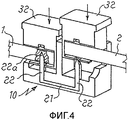
Фиг.4 - общий вид устройства в ходе фиксации первого провода согласно изобретению;4 is a General view of the device during fixing the first wire according to the invention;
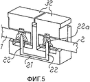
Фиг.5 - общий вид устройства после фиксации двух проводов согласно изобретению;5 is a General view of the device after fixing two wires according to the invention;
Фиг.6 - общий вид устройства после завершения установки согласно изобретению;6 is a General view of the device after installation is completed according to the invention;
Фиг.7 - общий вид устройства для соединения двух прерывистых проводов согласно второму варианту осуществления изобретения;7 is a General view of a device for connecting two intermittent wires according to a second embodiment of the invention;
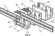
Фиг.8 - общий вид устройства под углом 180°, где показан разрез вдоль медианной плоскости проводов, согласно изобретению.Fig - a General view of the device at an angle of 180 °, which shows a section along the median plane of the wires, according to the invention.
Описание предпочтительных вариантов воплощения изобретенияDESCRIPTION OF PREFERRED EMBODIMENTS
Соединительное устройство (фиг.1-6) согласно первому варианту осуществления содержит корпус 10, изготовленный из изоляционного материала, образованный из двух половин 10a и 10b, которые могут быть скреплены в поперечном направлении Y-Y под прямым углом к продольному направлению X-X, параллельному продольному направлению проводов 1 и 2, которые должны быть вставлены в устройство (далее для ясности упоминаемое как клемма).The connecting device (FIGS. 1-6) according to the first embodiment comprises a
Упомянутое поперечное скрепление двух половин 10a и 10b может быть выполнено посредством упругого элемента 11, размещенного поперечно к одной (10b) из двух половин и снабженного крюком 11a, который может входить в соответствующую направляющую 11 другой половины 10a.Said lateral fastening of the two halves 10a and 10b can be carried out by means of an elastic element 11 arranged transversely to one (10b) of the two halves and provided with a hook 11a, which can enter the corresponding guide 11 of the other half 10a.
Две половины 10a, 10b дополнительно определяют направляющую 12, внутри которой размещен элемент 20, позволяющий определять электрическую непрерывность между двумя проводами 1 и 2, соединенными посредством клеммы. В описываемом варианте осуществления токопроводящий элемент 20 имеет практически U-образную форму, при этом его подложка 21 проходит в продольном направлении, а ответвления 22 проходят в направлении Z-Z под прямым углом к плоскости, заданной продольным направлением X-X и поперечным направлением Y-Y. Свободный конец каждого U-образного ответвления 22 преимущественно имеет наконечник 22a, который предназначен для облегчения вхождения ответвления 22 токопроводящего элемента 20 в соответствующий провод 1 или 2.The two halves 10a, 10b further define a guide 12, inside of which an
Внутри каждой половины 10a, 10b сформированы направляющие 13, предназначенные (после скрепления двух половин 10a, 10b) для формирования направляющей для скольжения в направлении, параллельном направлению Z-Z скользящего контакта 30, предназначенного для формирования механического элемента фиксации и удержания соответствующих проводов 1, 2.Inside each half 10a, 10b, guides 13 are formed, intended (after fastening the two halves 10a, 10b) to form a sliding guide in the direction parallel to the Z-Z direction of the sliding
Скользящий контакт 30 имеет корпус 31, геометрически эквивалентный направляющей 13, внутри которой должна скользить головка 32, с большей поверхностью, чтобы давать возможность скользящему контакту 30 проталкиваться в направлении наконечника 22a проводящего элемента 22 и формировать конец ударного упора скользящего контакта. В предпочтительном варианте осуществления направляющая 13 имеет одну или более зубчатых реек 13a для соединения с соответствующей рейкой 31a корпуса 31 скользящего контакта. Ориентация зубцов такова, чтобы обеспечивать возможность скольжения скользящего контакта 30 в направлении внутренней части корпуса и не допускать движения в противоположную сторону наружу скользящего контакта.The sliding
В корпусе 31 каждого скользящего контакта 30 дополнительно сформирована практически круглая направляющая 33, проходящая в продольном направлении и открытая снаружи, чтобы можно было вставить в продольном направлении соответствующий провод 1, 2 в направляющую 33.In the
В диаметральном положении направляющая 33 дополнительно представляет апертуру 33a, размещенную на оси ответвлений 22 токопроводящего элемента 20 и обеспечивающую возможность прохождения соответствующего ответвления 22 через апертуру.In the diametrical position, the
На внешней поверхности под прямыми углами к продольному направлению вставления провода корпус 31 скользящего контакта дополнительно представляет направленный кверху V-образный раструб 34 для направления скользящего контакта 30 по соответствующему проводу 1, 2.On the outer surface at right angles to the longitudinal direction of the insertion of the wire, the sliding
Работа устройства согласно изобретению осуществляется следующим образом.The operation of the device according to the invention is as follows.
В нормальном режиме клемма имеет два скользящих контакта 30, поднятых наружу (фиг.3), в этом режиме обеспечена возможность легкого вставления проводов 1, 2 в соответствующую продольную направляющую 33 без необходимости предварительной зачистки проводов.In normal mode, the terminal has two
После вставления проводов 1 и 2 в соответствующую направляющую 33 к головке 32 прикладывается сила соответствующего скользящего контакта 30 для опускания внутрь корпуса 10.After inserting the
Провода 1 и 2 проталкиваются в направлении наконечников 22a ответвлений 22 U-образного токопроводящего элемента 20; наконечники при вхождении внутрь соответствующего провода 1, 2 создают его электрическую непрерывность.The
Таким образом, устройство согласно настоящему изобретению позволяет восстанавливать электрическую непрерывность посредством соединения проводов без необходимости их зачистки, без дополнительных инструментов и без частей, находящихся под напряжением, доступных снаружи.Thus, the device according to the present invention allows to restore electrical continuity by connecting the wires without the need for stripping, without additional tools and without live parts accessible from the outside.
Хотя представлено описание для соединения двух проводов (1, 2), клемма согласно настоящему изобретению также может быть выполнена:Although a description is provided for connecting two wires (1, 2), a terminal according to the present invention can also be made:
- в виде одного блока с корпусом (10) из двух половин и одним зажимным скользящим контактом (30) для формирования части устройств в виде одного целого, таких как штепсельные разъёмы или гнезда (по сути, известны и, следовательно, не показаны), которые включаются во внешнюю часть головки скользящего контакта 30 и апертуры продольной направляющей 33 для вставления соответствующих проводов 1, 2;- in the form of one unit with a housing (10) of two halves and one clamping sliding contact (30) to form part of the devices as a whole, such as plug connectors or sockets (in fact, known and, therefore, not shown), which are included in the outer part of the head of the sliding
- в виде множества клемм, которые могут быть использованы в электрических щитках или панелях и т.п.;- in the form of many terminals that can be used in electrical panels or panels, etc .;
- клемма позволяет вставлять провода и обеспечивать электрическое соединение быстро и легко даже неспециалистам.- The terminal allows you to insert wires and provide an electrical connection quickly and easily even to non-specialists.
На фиг.7 и 8 показан второй вариант осуществления устройства согласно изобретению для соединения пары прерывистых проводов или кабелей 1, 2.7 and 8 show a second embodiment of a device according to the invention for connecting a pair of intermittent wires or
Кратко поясняются только части, структурно отличные от частей предыдущего варианта осуществления.Only parts structurally different from the parts of the previous embodiment are briefly explained.
В этом случае корпус 10 устройства изготовлен в виде одного модуля, а не из двух модулей, которые можно соединить вместе, и соединен с идентичными корпусами так, чтобы формировать выводной щиток.In this case, the
Поскольку две пары прерывистых проводов 1, 2 должны быть соединены, каждый скользящий контакт 30 имеет две наложенные направляющие или отверстия 33 для размещения конца соответствующих пар проводов 1 и 2. U-образный токопроводящий элемент 20 имеет подложку 21, заглубленную в подложку корпуса 10, и ответвления 22, которые выходят в соответствующие пары проводов 1 и 2, когда скользящие контакты 30 опущены в рабочую позицию. Таким образом, каждое ответвление 22 или токопроводящий элемент 20 устанавливает электрическую непрерывность между парой проводов 1 и парой проводов 2, соответственно, и подложка 21 токопроводящего элемента 20 устанавливает электрическую непрерывность между парой проводов 1 и парой проводов 2.Since two pairs of
В этом варианте осуществления рейки 13a, 31a заменены на размещенные друг напротив друга зубцы 13a, 31a, которые обеспечивают плотную фиксацию скользящего контакта 30 в корпусе 10, а также возможность разборки клеммы при необходимости.In this embodiment, the
Claims (14)
Applications Claiming Priority (2)
| Application Number | Priority Date | Filing Date | Title |
|---|---|---|---|
| IT001463A ITMI20041463A1 (en) | 2004-07-20 | 2004-07-20 | DEVICE FOR THE ELECTRICAL CONNECTION OF DISCONTINUOUS CONDUCTORS |
| ITMI2004A001463 | 2004-07-20 |
Publications (2)
| Publication Number | Publication Date |
|---|---|
| RU2007106084A RU2007106084A (en) | 2008-08-27 |
| RU2346366C2 true RU2346366C2 (en) | 2009-02-10 |
Family
ID=35106697
Family Applications (1)
| Application Number | Title | Priority Date | Filing Date |
|---|---|---|---|
| RU2007106084/09A RU2346366C2 (en) | 2004-07-20 | 2005-07-19 | Device for electrical connection of discontinuous wires |
Country Status (11)
| Country | Link |
|---|---|
| US (1) | US7731521B2 (en) |
| EP (1) | EP1769566B1 (en) |
| JP (1) | JP4510886B2 (en) |
| CN (1) | CN100508284C (en) |
| AT (1) | ATE384347T1 (en) |
| BR (1) | BRPI0513607A (en) |
| DE (1) | DE602005004414T2 (en) |
| ES (1) | ES2300037T3 (en) |
| IT (1) | ITMI20041463A1 (en) |
| RU (1) | RU2346366C2 (en) |
| WO (1) | WO2006008131A1 (en) |
Families Citing this family (11)
| Publication number | Priority date | Publication date | Assignee | Title |
|---|---|---|---|---|
| US7806710B2 (en) * | 2007-02-27 | 2010-10-05 | Samsung Electronics Co., Ltd. | Lamp holding unit |
| JP5390792B2 (en) * | 2008-05-23 | 2014-01-15 | 古河電気工業株式会社 | Connecting member |
| US7922541B2 (en) * | 2008-10-17 | 2011-04-12 | Barco Nv | Cable connector |
| US8647147B2 (en) * | 2010-03-09 | 2014-02-11 | Nii Northern International Inc. | Dual conductor cable connector |
| USD645406S1 (en) * | 2010-03-16 | 2011-09-20 | Nii Northern International Inc. | Portion of electrical connector |
| US9184515B1 (en) * | 2012-09-28 | 2015-11-10 | Anthony Freakes | Terminal blocks for printed circuit boards |
| US9543729B2 (en) | 2013-08-19 | 2017-01-10 | Sullstar Technologies, Inc | Electrical connector with removable external load bar, and method of its use |
| US9577352B2 (en) | 2015-01-29 | 2017-02-21 | Home Depot Product Authority, LLP | Electrical connectors and related methods |
| AU2017204634A1 (en) * | 2017-07-06 | 2019-01-24 | Brightgreen Pty Ltd | Electrical connector |
| DE102017127382A1 (en) * | 2017-11-21 | 2019-05-23 | Lisa Dräxlmaier GmbH | ELECTRICAL CONNECTOR AND ELECTRICAL LINEAR ASSEMBLY EQUIPPED THEREwith |
| WO2020006586A1 (en) * | 2018-07-03 | 2020-01-09 | Bertelt Peter | Connecting device |
Family Cites Families (35)
| Publication number | Priority date | Publication date | Assignee | Title |
|---|---|---|---|---|
| GB699856A (en) | 1950-01-05 | 1953-11-18 | Peter Maurice Landauer | A connector device for use with electric cable or flex |
| US2745065A (en) * | 1955-03-15 | 1956-05-08 | Charles H Maher | Coupling for coaxial high frequency transmission lines |
| US3115541A (en) | 1962-05-21 | 1963-12-24 | Pullman Inc | Electrical wiring connector |
| US3718888A (en) * | 1971-01-04 | 1973-02-27 | Bell Telephone Labor Inc | Universal connector for cable conductors |
| US3890029A (en) * | 1974-02-19 | 1975-06-17 | Thomas & Betts Corp | Partitioned electrical connector |
| US3899236A (en) * | 1974-06-24 | 1975-08-12 | Amerace Corp | Electrical connector |
| DE3110144C2 (en) * | 1981-03-16 | 1983-05-19 | Minnesota Mining and Manufacturing Co., 55133 Saint Paul, Minn. | Strain relief for electrical conductors in an electrical connector for non-stripped conductors |
| JPS57194466A (en) | 1981-05-22 | 1982-11-30 | Fujikura Ltd | Connector |
| US4436361A (en) * | 1981-11-20 | 1984-03-13 | Amp Incorporated | Hermaphroditic back shell cover |
| FR2598039B1 (en) * | 1986-04-28 | 1990-09-21 | Alsthom Cgee | SLOT CONNECTION ARRANGEMENT FOR ELECTRIC WIRE AND CORRESPONDING CONNECTION TOOL END CAP |
| US4781615A (en) * | 1987-08-31 | 1988-11-01 | Amp Incorporated | Cable terminating cover retention system |
| US4865564A (en) * | 1988-06-10 | 1989-09-12 | American Telephone And Telegraph Company | Wall mounted connecting block |
| US4897041A (en) * | 1989-03-21 | 1990-01-30 | Amp Incorporated | Electrical connector having a cable terminating cover retention system and a strain relief therefor |
| DE4008739A1 (en) * | 1990-03-19 | 1991-09-26 | Rose Walter Gmbh & Co Kg | CABLE CONNECTOR |
| US5080606A (en) * | 1990-11-05 | 1992-01-14 | Minnesota Mining And Manufacturing Company | Stacked in-line insulation displacement connector |
| US5338220A (en) * | 1992-05-19 | 1994-08-16 | The Whitaker Corporation | Electrical connector housing assembly and an electrical terminal therefor |
| JPH0629006U (en) * | 1992-09-14 | 1994-04-15 | 矢崎総業株式会社 | Insulation displacement connector |
| US5339232A (en) * | 1993-01-12 | 1994-08-16 | Lin Te H | Miniature light set |
| US5498172A (en) * | 1993-07-30 | 1996-03-12 | Sunx Kabushiki Kaisha | Electrical connector for interconnecting parallel multiconductor cables |
| FR2718295B1 (en) * | 1994-03-30 | 1996-04-26 | Alcatel Cable Interface | Connection push-button and connection strip fitted with such push-buttons. |
| US5836791A (en) * | 1994-10-21 | 1998-11-17 | Psi Telecommunications, Inc. | Modular telecommunications terminal block |
| AU678743B2 (en) * | 1995-03-31 | 1997-06-05 | Matsushita Electric Works Ltd. | Lever modular jack electrical connector |
| US5820404A (en) * | 1995-07-10 | 1998-10-13 | Sumitomo Wiring Systems, Ltd. | Terminal and cramping connector |
| US6328592B1 (en) * | 1996-06-07 | 2001-12-11 | Molex Incorporated | Electrical connector with cable clamping means |
| DE29617190U1 (en) | 1996-10-02 | 1997-02-06 | Hirschmann Richard Gmbh | Device for the electrical connection of at least two multi-core, preferably two-core conductors |
| DE19642445C1 (en) * | 1996-10-15 | 1998-03-05 | Krone Ag | Connector |
| US5975938A (en) * | 1998-06-03 | 1999-11-02 | Robert A. Libby | Quick connect electrical connector for multi conductor insulated cable wiring |
| US6315595B1 (en) * | 1998-06-03 | 2001-11-13 | Corning Cable Systems Llc | Modular IDC terminal |
| FR2797353B1 (en) * | 1999-08-04 | 2001-12-14 | Conception & Dev Michelin Sa | ELECTRICAL CONNECTOR USING BODIES PENETRATING IN INSULATION |
| US6159035A (en) * | 1999-11-23 | 2000-12-12 | Audio Components International, Inc. | Connector assembly having means for penetrating the insulation and establishing electrical connection with the wires |
| US6305967B1 (en) * | 1999-11-23 | 2001-10-23 | Niles Audio Corporation | Connector assembly having means for penetrating the insulation and establishing electrical connection with the wires |
| DE10039637C2 (en) * | 2000-08-09 | 2002-06-27 | Krone Gmbh | Connection element and method for tool-free electrical contacting of an electrical wire |
| US6827600B2 (en) * | 2002-03-20 | 2004-12-07 | Yazaki Corporation | Paired electrical cable connector |
| US20050227529A1 (en) * | 2004-04-08 | 2005-10-13 | Gelcore Llc | Multi-conductor parallel splice connection |
| US7156689B2 (en) * | 2005-01-14 | 2007-01-02 | Tyco Electronics Corporation | Dual wire connector with multiple press fit connection |
-
2004
- 2004-07-20 IT IT001463A patent/ITMI20041463A1/en unknown
-
2005
- 2005-07-19 RU RU2007106084/09A patent/RU2346366C2/en not_active IP Right Cessation
- 2005-07-19 ES ES05764216T patent/ES2300037T3/en active Active
- 2005-07-19 BR BRPI0513607-5A patent/BRPI0513607A/en not_active IP Right Cessation
- 2005-07-19 EP EP05764216A patent/EP1769566B1/en not_active Not-in-force
- 2005-07-19 WO PCT/EP2005/007840 patent/WO2006008131A1/en active IP Right Grant
- 2005-07-19 DE DE602005004414T patent/DE602005004414T2/en active Active
- 2005-07-19 AT AT05764216T patent/ATE384347T1/en not_active IP Right Cessation
- 2005-07-19 JP JP2007521884A patent/JP4510886B2/en not_active Expired - Fee Related
- 2005-07-19 US US11/630,786 patent/US7731521B2/en not_active Expired - Fee Related
- 2005-07-19 CN CNB2005800244096A patent/CN100508284C/en not_active Expired - Fee Related
Also Published As
| Publication number | Publication date |
|---|---|
| JP2008507105A (en) | 2008-03-06 |
| DE602005004414D1 (en) | 2008-03-06 |
| BRPI0513607A (en) | 2008-05-13 |
| DE602005004414T2 (en) | 2008-12-24 |
| US7731521B2 (en) | 2010-06-08 |
| EP1769566A1 (en) | 2007-04-04 |
| EP1769566B1 (en) | 2008-01-16 |
| ES2300037T3 (en) | 2008-06-01 |
| CN100508284C (en) | 2009-07-01 |
| RU2007106084A (en) | 2008-08-27 |
| WO2006008131A1 (en) | 2006-01-26 |
| JP4510886B2 (en) | 2010-07-28 |
| US20090197455A1 (en) | 2009-08-06 |
| ITMI20041463A1 (en) | 2004-10-20 |
| CN1989655A (en) | 2007-06-27 |
| ATE384347T1 (en) | 2008-02-15 |
Similar Documents
| Publication | Publication Date | Title |
|---|---|---|
| RU2346366C2 (en) | Device for electrical connection of discontinuous wires | |
| ES2409204T3 (en) | Serial electrical terminal block | |
| CN1941508B (en) | Electrical connection arrangement | |
| US20050042912A1 (en) | Connector apparatus adapted for the direct plug-in connection of conductors | |
| RU2005122320A (en) | DISTRIBUTION DEVICE USING THE INSERTED MODULAR SYSTEM OF TIRES WITHOUT CONDUCTIVE PARTS ON THE FACE | |
| US9293848B2 (en) | Electrical connector for use with printed circuit boards | |
| US5890925A (en) | Electrical connector with screw-on or twist-on electrical contacts | |
| RU2007146440A (en) | CONNECTING DEVICE FOR LOW-VOLTAGE ELECTRIC BOARDS | |
| ATE363140T1 (en) | BRANCH DEVICE | |
| JPH1083851A (en) | Earth module | |
| WO2015148251A1 (en) | Wiring apparatus | |
| US9385486B2 (en) | Socket module, electrosurgical device, and set with a socket module | |
| CN109586050A (en) | A kind of Electric Wires & Cables connector of mechanical automation equipment | |
| IL111677A (en) | Electrical connector having a conductor holding block | |
| JPH08115757A (en) | Cable-wire connecting terminal block | |
| JP2011174807A (en) | Uninterruptible replacement tool for watt-hour meter | |
| ES2539129T3 (en) | A quick-release contact designed to fit a terminal board, in particular for an electronic ignition device for home appliances | |
| JPH11250947A (en) | Outlet for power source and switch | |
| US20120322300A1 (en) | Electrical quick connection apparatus | |
| CN216214634U (en) | Convenient two-way terminal for power distribution test terminal of dismantling | |
| CN218241737U (en) | Wiring terminal of circuit breaker | |
| JP2719904B2 (en) | Uninterruptible bypass device for instrument | |
| KR200410750Y1 (en) | SPLICE-PACK for INLINE CONNECTER | |
| JPH0743955Y2 (en) | Centralized connection connector | |
| KR20070021805A (en) | Connection apparatus for source of electricity distribution |
Legal Events
| Date | Code | Title | Description |
|---|---|---|---|
| MM4A | The patent is invalid due to non-payment of fees |
Effective date: 20150720 |