RU2344286C2 - Method and device for real-time acoustic monitoring properties of foam and aerated liquids - Google Patents
Method and device for real-time acoustic monitoring properties of foam and aerated liquids Download PDFInfo
- Publication number
- RU2344286C2 RU2344286C2 RU2006146964/03A RU2006146964A RU2344286C2 RU 2344286 C2 RU2344286 C2 RU 2344286C2 RU 2006146964/03 A RU2006146964/03 A RU 2006146964/03A RU 2006146964 A RU2006146964 A RU 2006146964A RU 2344286 C2 RU2344286 C2 RU 2344286C2
- Authority
- RU
- Russia
- Prior art keywords
- foam
- quality
- receiver
- sound
- emitter
- Prior art date
Links
Images


Classifications
-
- G—PHYSICS
- G01—MEASURING; TESTING
- G01H—MEASUREMENT OF MECHANICAL VIBRATIONS OR ULTRASONIC, SONIC OR INFRASONIC WAVES
- G01H5/00—Measuring propagation velocity of ultrasonic, sonic or infrasonic waves, e.g. of pressure waves
-
- G—PHYSICS
- G01—MEASURING; TESTING
- G01N—INVESTIGATING OR ANALYSING MATERIALS BY DETERMINING THEIR CHEMICAL OR PHYSICAL PROPERTIES
- G01N29/00—Investigating or analysing materials by the use of ultrasonic, sonic or infrasonic waves; Visualisation of the interior of objects by transmitting ultrasonic or sonic waves through the object
- G01N29/02—Analysing fluids
-
- G—PHYSICS
- G01—MEASURING; TESTING
- G01N—INVESTIGATING OR ANALYSING MATERIALS BY DETERMINING THEIR CHEMICAL OR PHYSICAL PROPERTIES
- G01N29/00—Investigating or analysing materials by the use of ultrasonic, sonic or infrasonic waves; Visualisation of the interior of objects by transmitting ultrasonic or sonic waves through the object
- G01N29/04—Analysing solids
- G01N29/07—Analysing solids by measuring propagation velocity or propagation time of acoustic waves
-
- G—PHYSICS
- G01—MEASURING; TESTING
- G01N—INVESTIGATING OR ANALYSING MATERIALS BY DETERMINING THEIR CHEMICAL OR PHYSICAL PROPERTIES
- G01N2291/00—Indexing codes associated with group G01N29/00
- G01N2291/02—Indexing codes associated with the analysed material
- G01N2291/024—Mixtures
- G01N2291/02433—Gases in liquids, e.g. bubbles, foams
-
- G—PHYSICS
- G01—MEASURING; TESTING
- G01N—INVESTIGATING OR ANALYSING MATERIALS BY DETERMINING THEIR CHEMICAL OR PHYSICAL PROPERTIES
- G01N2291/00—Indexing codes associated with group G01N29/00
- G01N2291/02—Indexing codes associated with the analysed material
- G01N2291/028—Material parameters
- G01N2291/02836—Flow rate, liquid level
-
- G—PHYSICS
- G01—MEASURING; TESTING
- G01N—INVESTIGATING OR ANALYSING MATERIALS BY DETERMINING THEIR CHEMICAL OR PHYSICAL PROPERTIES
- G01N2291/00—Indexing codes associated with group G01N29/00
- G01N2291/10—Number of transducers
- G01N2291/102—Number of transducers one emitter, one receiver
Landscapes
- Physics & Mathematics (AREA)
- General Physics & Mathematics (AREA)
- Biochemistry (AREA)
- Life Sciences & Earth Sciences (AREA)
- Chemical & Material Sciences (AREA)
- Analytical Chemistry (AREA)
- Health & Medical Sciences (AREA)
- General Health & Medical Sciences (AREA)
- Acoustics & Sound (AREA)
- Immunology (AREA)
- Pathology (AREA)
- Investigating Or Analyzing Materials By The Use Of Ultrasonic Waves (AREA)
- Geophysics And Detection Of Objects (AREA)
Abstract
Description
Область техникиTechnical field
Настоящее изобретение относится к способу и устройству акустического мониторинга свойств пены и аэрированных многофазных жидкостей со сложной реологией в реальном времени.The present invention relates to a method and apparatus for acoustic monitoring the properties of foam and aerated multiphase liquids with complex real-time rheology.
Изобретение может быть использовано для определения в реальном времени качества пены и аэрированных жидкостей, т.е. оценки доли газа в жидкостях, содержащих газ, в частности, в нефтедобывающей промышленности при обслуживании скважин, включая цементирование скважин или гидравлический разрыв пласта. Изобретение может быть использовано в любой области промышленности, например, в пищевой промышленности, при производстве газированных напитков, а также в фармацевтической промышленности.The invention can be used to determine in real time the quality of the foam and aerated liquids, i.e. estimating the proportion of gas in liquids containing gas, in particular in the oil industry for servicing wells, including well cementing or hydraulic fracturing. The invention can be used in any industry, for example, in the food industry, in the production of carbonated drinks, as well as in the pharmaceutical industry.
Предшествующий уровень техникиState of the art
Определение: отношение объема газа, содержащегося в жидкости, ко всему объему жидкости и газа называется качеством и обозначается буквой Г.Definition: the ratio of the volume of gas contained in a liquid to the entire volume of liquid and gas is called quality and is indicated by the letter G.
![]()
![]()
где V1 - объем газа, V - полный объем жидкости и газа.where V 1 is the volume of gas, V is the total volume of liquid and gas.
По определению, Г находится в пределах от 0 до 1. Если Г≤0,5, жидкость называется аэрированной жидкостью, если Г>0,5, жидкость называется пеной. В данном описании для обоих случаев будет использоваться термин «пена».By definition, G is in the range from 0 to 1. If G жидкость 0.5, the liquid is called aerated liquid, if G> 0.5, the liquid is called foam. In this description, for both cases, the term "foam" will be used.
Например, качество пены 0,9 означает, что пена состоит на 90% из газа и на 10% из жидкости.For example, a foam quality of 0.9 means that the foam is 90% gas and 10% liquid.
Цементирование скважин необходимо для обеспечения долговременной стабильности скважин при воздействии пластового давления. Цементирование выполняют путем закачивания цементного раствора в скважину через колонну труб, после чего выжидают некоторое время, пока раствор затвердеет. В некоторых случаях целесообразно добавлять некоторое количество газа в закачиваемый раствор для его вспенивания и получения более легкого цементного раствора, при этом необходимо правильно определять качество «Г» закачиваемого вспененного цементного раствора. Правильное определение качества вспененного цементного раствора является важной составляющей при выполнении работ, поскольку является важным фактором, определяющим механические свойства цемента и, таким образом, стабильность скважин.Well cementing is necessary to ensure long-term stability of wells when exposed to reservoir pressure. Cementing is performed by pumping a cement slurry into the well through a pipe string, after which they wait a while until the slurry hardens. In some cases, it is advisable to add a certain amount of gas to the injected mortar to foame it and obtain a lighter cement mortar, and it is necessary to correctly determine the quality “G” of the injected foamed cement mortar. The correct determination of the quality of foamed cement mortar is an important component in the performance of work, as it is an important factor determining the mechanical properties of cement and, thus, the stability of wells.
Гидравлический разрыв пласта осуществляется для повышения продуктивности скважины путем формирования или расширения каналов, соединяющих ствол скважины с нефтеносным пластом. Эта операция выполняется путем закачивания жидкости для гидравлического разрыва в скважину, проходящую через подземные пласты породы, и нагнетания жидкости для гидравлического разрыва в подземные пласты породы под давлением. Пласты породы или скальные породы растрескиваются, при этом образуется или расширяется один или несколько разрывов. Жидкость для гидравлического разрыва содержит расклинивающий наполнитель (проппант), который занимает объем разрыва и препятствует закрытию разрыва. Таким образом обеспечивается повышение потока добываемой нефти, газа или воды. В некоторых случаях в качестве жидкости для гидравлического разрыва пласта используется пена или аэрированная жидкость для того, чтобы либо уменьшить давление в устье скважины, либо улучшить очистку разрыва от скважинных жидкостей. В этом случае также необходимо правильно определить качество «Г» пены, используемой для гидравлического разрыва пласта.Hydraulic fracturing is carried out to increase well productivity by forming or expanding channels connecting the wellbore to the oil reservoir. This operation is performed by pumping hydraulic fracturing fluid into a well passing through underground rock formations and injecting hydraulic fracturing fluid into underground rock formations under pressure. Rock strata or rock formations crack, with the formation or expansion of one or more gaps. The hydraulic fracturing fluid contains proppant, which occupies the fracture volume and prevents the fracture from closing. This ensures an increase in the flow of produced oil, gas or water. In some cases, foam or aerated fluid is used as the hydraulic fracturing fluid to either reduce the pressure at the wellhead or to improve the cleanup of the fracture from the wellbore fluids. In this case, it is also necessary to correctly determine the quality of the “G” foam used for hydraulic fracturing.
Определение качества пены в промышленности обычно выполняется путем непосредственного измерения объема газа и жидкости в пене, причем измерения выполняются различными способами и различными инструментами. Например, это можно реализовать путем создания специального отводного контура по пути движения пены, который содержит камеру для выделения газа из пены, и прямого измерения объема газа или измерения расхода каждой из фаз, составляющих пену, посредством расходомера.Determining the quality of the foam in industry is usually done by directly measuring the volume of gas and liquid in the foam, and the measurements are carried out in various ways and with different tools. For example, this can be realized by creating a special branch circuit along the path of the foam, which contains a chamber for separating gas from the foam, and directly measuring the volume of gas or measuring the flow rate of each of the phases that make up the foam, using a flow meter.
В патенте US 6461414 раскрыта система для определения и при необходимости управления ценообразованием жидкости, поступающей из подземной формации и проходящей через по меньшей мере один газожидкостной сепаратор, который обеспечивает отвод газа из пластового флюида, поступающего из подземной формации. Система содержит датчик для измерения требуемого параметра потока газа, отделенного от пластового флюида, который является показателем пенообразования пластового флюида. Система содержит также процессор для обработки измеренных параметров и определения степени ценообразования пластового флюида.US Pat. No. 6,461,414 discloses a system for determining and, if necessary, controlling the pricing of a fluid coming from an underground formation and passing through at least one gas-liquid separator, which allows gas to be removed from the formation fluid coming from the underground formation. The system comprises a sensor for measuring a desired parameter of a gas flow separated from the formation fluid, which is an indicator of formation foam formation. The system also includes a processor for processing the measured parameters and determining the degree of formation fluid pricing.
Система дополнительно содержит газовый сепаратор, т.е. устройство для отделения части газа из газового потока для образования боковой фракции, при этом датчик обеспечивает измерение параметров потока боковой фракции. В качестве сепаратора может быть использован полый вал. В качестве датчика может быть использован денситометр, т.е. прибор для измерения плотности или оптической плотности флюида в потоке газа, либо датчик оптической плотности потока газа.The system further comprises a gas separator, i.e. a device for separating part of the gas from the gas stream to form a side fraction, while the sensor measures the parameters of the side fraction stream. As a separator, a hollow shaft can be used. As a sensor, a densitometer can be used, i.e. a device for measuring the density or optical density of a fluid in a gas stream, or a sensor for optical density of a gas stream.
Для определения уровня ценообразования осуществляется взятие пробы газа из сепаратора высокого давления и либо измерение плотности образца, либо измерение количества нефти. Устанавливается соответствие плотности или оптической плотности с уровнем ценообразования, полученный сигнал передается в устройство управления. Для управления ценообразованием осуществляется регулирование подачи по меньшей мере одной добавки, предназначенной для пенообразования.To determine the level of pricing, a gas sample is taken from a high-pressure separator and either a sample density is measured or a quantity of oil is measured. The correspondence of density or optical density with the level of pricing is established, the received signal is transmitted to the control device. To control pricing, the flow of at least one additive intended for foaming is controlled.
Недостатком указанной системы является то, что для определения качества пены в потоке необходимо осуществлять отвод части потока в обводной трубопровод для образования бокового потока. Система не позволяет определять качество пены непосредственно в трубопроводе, по которому протекает поток флюида из подземной формации. Использование сепаратора приводит к большим погрешностям при измерении качества пены.The disadvantage of this system is that to determine the quality of the foam in the stream, it is necessary to divert part of the stream to the bypass pipe to form a side stream. The system does not allow determining the quality of the foam directly in the pipeline through which the fluid flows from the underground formation. The use of a separator leads to large errors in measuring the quality of the foam.
В патенте США 5470749 раскрыт способ непрерывного измерения качества протекающего потока пара, который используется для инжектирования в скважины для улучшения добычи нефти, при давлении существенно выше атмосферного и комнатной температуре. Способ заключается в том, чтоUS Pat. No. 5,470,749 discloses a method for continuously measuring the quality of a flowing steam stream, which is used for injection into wells to improve oil production, at a pressure substantially above atmospheric and room temperature. The method is that
a) смешивают пар известного качества (отношение объема пара к объему пара и жидкости) с поверхностно-активным веществом не более 1 вес.% жидкой фазы пара для образования стабильной пены, имеющей качество, равное качеству пара,a) mix steam of known quality (the ratio of the volume of steam to the volume of steam and liquid) with a surfactant of not more than 1 wt.% the liquid phase of the vapor to form a stable foam having a quality equal to the quality of the vapor,
b) пропускают стабильную пену через неэлектропроводную экранированную капиллярную трубку и измеряют падение напряжения между двумя электродами, расположенными поперек заданной длины трубки, и падение давления через ту же заданную длину трубки,b) pass the stable foam through a non-conductive shielded capillary tube and measure the voltage drop between two electrodes located across a given length of the tube and the pressure drop through the same given length of the tube,
c) повторяют указанные шаги, используя пар различного качества,c) repeat the above steps using steam of different quality,
d) строят диаграмму зависимости между отношением падения напряжения и падением давления для определения качества пены (отношение объема пара к объему пара и жидкости) для каждого образца пара,d) build a diagram of the relationship between the ratio of the voltage drop and the pressure drop to determine the quality of the foam (the ratio of the volume of steam to the volume of steam and liquid) for each steam sample,
e) удаляют последовательность образцов потока пара неизвестного качества и повторяют шаги а), b) для каждого образца для определения отношения падения напряжения и давления стабильной пены, сформированной из указанного пара, и измеряют температуру стабильной пены, сформированной из указанного пара, для определения объема фазы жидкость-вода и вода-пар потока, формирующего стабильную пену,e) remove the sequence of samples of the steam flow of unknown quality and repeat steps a), b) for each sample to determine the ratio of the voltage drop and pressure of the stable foam formed from the specified steam, and measure the temperature of the stable foam formed from the specified steam to determine the phase volume liquid-water and water-vapor flow, forming a stable foam,
f) определяют качество каждого образца стабильной пены на шаге е) графически из взаимосвязи между качеством пены и соотношением падения напряжения и падения давления, вычерченного на шаге d), что равно качеству пара,f) determine the quality of each sample of stable foam in step e) graphically from the relationship between the quality of the foam and the ratio of the voltage drop and pressure drop drawn in step d), which is equal to the quality of the vapor,
g) конвертируют качество пара (отношение объема пара к объему пены), полученного на шаге f) для каждого образца, к качеству пара (масса пара на массу пара и жидкости), используя специфический объем фазы пара жидкость-вода и вода-пар, определенные на шаге е).g) convert the steam quality (ratio of steam volume to foam volume) obtained in step f) for each sample to the quality of steam (mass of steam per mass of steam and liquid) using the specific volume of the liquid-water and water-steam phases defined in step e).
Недостатком указанного способа является то, что для определения качества пара необходимо вначале его преобразовать в стабильную пену и осуществить отвод части потока в обводной трубопровод, из которого осуществляют отбор образцов.The disadvantage of this method is that in order to determine the quality of the steam, it is first necessary to convert it into a stable foam and to carry out the removal of part of the flow into a bypass pipe from which samples are taken.
В случае ответвления потока пены, например, при проведении операций гидравлического разрыва или цементирования способ не позволяет непосредственно определять распределение качества пены. В этом случае качество рассчитывают теоретически или путем численного моделирования, задавая при этом либо данные о качестве в доступных местах потока, например, в точке закачивания раствора, либо задавая диаграмму закачивания, либо и то, и другое. Такие измерения невозможно провести в промышленных условиях, когда необходимо проводить мониторинг удаленных недоступных участков, по которым осуществляется подвод пены.In the case of a branch of the foam flow, for example, during hydraulic fracturing or cementing operations, the method does not directly determine the foam quality distribution. In this case, the quality is calculated theoretically or by numerical simulation, setting either quality data in accessible places of the flow, for example, at the injection point of the solution, or setting the injection diagram, or both. Such measurements cannot be carried out in an industrial environment when it is necessary to monitor remote inaccessible areas along which foam is supplied.
Возможно также измерять качество пены не прямым путем, т.е. не путем измерения объемов газа и жидкости, образующих пену, а путем мониторинга физических характеристик пены.It is also possible to measure the quality of the foam in a non-direct way, i.e. not by measuring the volumes of gas and liquid forming the foam, but by monitoring the physical characteristics of the foam.
В качестве ближайшего технического решения можно рассматривать способ определения качества пены путем мониторинга физических характеристик пены, которые зависят от качества пены. Одной из таких характеристик является скорость звука в пене. Указанная зависимость скорости звука от качества пены раскрыта, например, в публикации А.Б.Вуда «Учебник по акустике» (Лондон, 1941 г.). Простейшим примером является двухфазная пена, состоящая из идеального газа и невязкой жидкости. Для такой пены скорость звука связана с качеством пены согласно уравнению:As the closest technical solution, we can consider a method for determining the quality of the foam by monitoring the physical characteristics of the foam, which depend on the quality of the foam. One such characteristic is the speed of sound in the foam. The indicated dependence of the speed of sound on the quality of the foam is disclosed, for example, in the publication of A.B. Wood, “Acoustic Textbook” (London, 1941). The simplest example is a two-phase foam, consisting of an ideal gas and an inviscid liquid. For such a foam, the speed of sound is related to the quality of the foam according to the equation:
![]()
![]()
где Cfm - скорость звука в пене, р - давление, ρfl - плотность жидкости, Г - качество пены, N - коэффициент политропного расширения (справочная величина, например, N=1 для изотермического процесса, N=1,4 для адиабатического процесса).where C fm is the speed of sound in the foam, p is the pressure, ρ fl is the density of the liquid, G is the quality of the foam, N is the coefficient of polytropic expansion (reference value, for example, N = 1 for the isothermal process, N = 1.4 for the adiabatic process )
Зависимость скорости звука в водной пене при р=10 МПа представлена на Фиг.1. Следует отметить, что типичная скорость Cfm звука в пене во много раз меньше скорости Clq звука в базовой жидкости. Эта зависимость хорошо подтверждается экспериментально (см., например, К.Falk, J.-S.Gudmundsson «Многофазные импульсы давления для быстродействующих клапанов», SPE 56526 или B.S.Gardiner «Измерения предела текучести в водных пенах в сухом приближении», журнал Rheology, 42(6), Nov/Dec, 1998). В публикации С.В.Киффер «Скорость звука в смесях жидкость-газ, например, вода-воздух и вода-пар» (журнал Geophys. Res., том 82, В20, 1977 г., стр.2895-2904) приведен пример современного теоретического анализа, который также подтверждает применимость формулы (1) для определения качества пены.The dependence of the speed of sound in water foam at p = 10 MPa is presented in figure 1. It should be noted that the typical speed C fm of sound in the foam is many times less than the speed C lq of sound in the base fluid. This dependence is well confirmed experimentally (see, for example, K. Falk, J.-S. Gudmundsson "Multiphase pressure pulses for high-speed valves", SPE 56526 or BSGardiner "Measurement of yield strength in aqueous foams in the dry approximation", Rheology, 42 (6), Nov / Dec, 1998). In S.V. Kieffer's publication “The speed of sound in liquid-gas mixtures, for example, water-air and water-steam” (Geophys. Res., Volume 82, B20, 1977, pp. 2895-2904), an example is given modern theoretical analysis, which also confirms the applicability of formula (1) for determining the quality of the foam.
Для многофазных многокомпонентных смесей жидкостей и газов зависимость скорости звука от отношения объемов фаз может быть либо измерена в лабораторных условиях (см., например, B.S.Gardiner «Измерения предела текучести в водных пенах в сухом приближении»), либо рассчитана теоретически (см., например, В.Herzhaft «Реология водных пен: обзор отдельных экспериментальных работ», RE. IFP, Vol.54 (1999), No.5, pp.587-596), в которой раскрыт способ определения сжимаемости смеси, которая является основной величиной, от которой зависит скорость звука в среде.For multiphase multicomponent mixtures of liquids and gases, the dependence of the sound velocity on the ratio of phase volumes can either be measured in laboratory conditions (see, for example, BSGardiner "Measurement of yield strength in water foams in the dry approximation"), or theoretically calculated (see, for example , Herzhaft B. “Rheology of water foams: a review of selected experimental works”, RE. IFP, Vol.54 (1999), No.5, pp.587-596), which discloses a method for determining the compressibility of a mixture, which is the main value, on which the speed of sound in the medium depends.
Таким образом, качество пены может быть установлено путем измерения давления и скорости звука в пене, при этом конкретный вид зависимости качества пены от давления и скорости звука может быть установлен либо аналитически, либо экспериментально, либо путем численного моделирования. В дальнейшем описании такую зависимость называют «таблицей значений».Thus, the quality of the foam can be established by measuring the pressure and speed of sound in the foam, while the specific form of the dependence of the quality of the foam on pressure and speed of sound can be established either analytically or experimentally, or by numerical simulation. In the following description, such a relationship is called a “value table”.
Благодаря строгой зависимости скорости звука от качества пены появилась возможность определять качество пены по результатам объединенных измерений скорости звука и давления в пене. Эта возможность становится все более привлекательной, в частности, в связи с появлением новых технологий измерения давления в скважине в реальном времени, например, путем использования оптического волокна (см, например, J.Lovell и др. IPC, Хьюстон, США, «Регистрация при моделировании», Симпозиум Шлюмберже по нефтедобыче, 2004).Due to the strict dependence of the speed of sound on the quality of the foam, it became possible to determine the quality of the foam based on the results of combined measurements of the speed of sound and pressure in the foam. This feature is becoming increasingly attractive, in particular, due to the advent of new technologies for measuring pressure in the well in real time, for example, by using optical fiber (see, for example, J. Lovell et al. IPC, Houston, USA, “Registration with modeling ”, Schlumberger Symposium on Oil Production, 2004).
Зависимость скорости звука от качества пены используется в измерительных приборах. Известно устройство для измерения скорости звука в бинарной смеси газов для определения изменения концентрации одного из компонентов смеси (см., например, Тинж Дж.Т. и др. «Ультразвуковой газовый анализатор высокого разрешения для определения состава бинарных смесей», журнал Phys. E: Scientific Instrument, 19, 1986).The dependence of the speed of sound on the quality of the foam is used in measuring instruments. A device for measuring the speed of sound in a binary gas mixture to determine the change in the concentration of one of the components of the mixture (see, for example, Tinzh J.T. et al. "High-resolution ultrasonic gas analyzer for determining the composition of binary mixtures", journal Phys. E: Scientific Instrument, 19, 1986).
Известен также способ измерения расхода многофазной жидкости в морских скважинах (см., например, патент US 5741978 или Дж.С.Гандмандсон и др. «Способ определения расхода жидкости», «Измерение параметров смесей газ-жидкости при помощи импульсов давления», «Измерение параметров двухфазных потоков на основе распространения импульсов давления». В основу указанных способов положена указанная зависимость скорости звука от качества пены.There is also a method of measuring the flow rate of multiphase fluid in offshore wells (see, for example, US Pat. No. 5,741,978 or J.S. Gandmanson et al. “Method for determining fluid flow rate”, “Measurement of parameters of gas-liquid mixtures using pressure pulses”, “Measurement parameters of two-phase flows based on the propagation of pressure pulses. ”These methods are based on the indicated dependence of the speed of sound on the quality of the foam.
Однако известные способы и устройства не позволяют определять в реальном времени путем акустических измерений качество пены, которая используется, например, для цементирования скважин или для гидравлического разрыва пластов, а также в других отраслях промышленности.However, the known methods and devices do not allow to determine in real time by acoustic measurements the quality of the foam, which is used, for example, for cementing wells or for hydraulic fracturing, as well as in other industries.
Краткое изложение существа изобретенияSummary of the invention
Технической задачей настоящего изобретения является создание способа и устройства мониторинга качества пены, которые позволили бы в реальном времени осуществлять измерения скорости звука и давления пены и по результатам измерений определять качество пены в реальном времени.An object of the present invention is to provide a method and device for monitoring the quality of the foam, which would allow real-time measurements of the speed of sound and pressure of the foam and the results of measurements to determine the quality of the foam in real time.
Поставленная задача решена путем создания способа акустического мониторинга качества пены в реальном времени, который заключается в том, чтоThe problem is solved by creating a method for acoustic monitoring of the quality of the foam in real time, which consists in the fact that
размещают по меньшей мере одну пару излучатель-приемник в непосредственной близости от потока пены,place at least one pair of emitter-receiver in the immediate vicinity of the foam flow,
излучают по меньшей мере один акустический импульс,emit at least one acoustic impulse,
регистрируют время, за которое акустический импульс пройдет от излучателя к приемнику,register the time during which the acoustic pulse passes from the emitter to the receiver,
определяют скорость акустического импульса (скорость звука) путем анализа акустического отклика приемника,determine the speed of the acoustic pulse (speed of sound) by analyzing the acoustic response of the receiver,
определяют давление в пене в области между излучателем и приемником,determine the pressure in the foam in the region between the emitter and the receiver,
рассчитывают качество Г пены согласно уравнению:calculate the quality of G foam according to the equation:
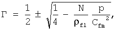
где Сfm - скорость звука в пене, р - давление, ρfl - плотность жидкости, Г - качество пены, N - коэффициент политропного расширения (справочная величина, N=1 для изотермического процесса, N=1,4 для адиабатического процесса), в случае пены, составленной из идеального газа и идеальной жидкости, или, в более сложных случаях, находят его из таблицы значений.where C fm is the speed of sound in the foam, p is the pressure, ρ fl is the density of the liquid, G is the quality of the foam, N is the coefficient of polytropic expansion (reference value, N = 1 for the isothermal process, N = 1.4 for the adiabatic process), in the case of a foam made up of an ideal gas and an ideal liquid, or, in more complex cases, find it from the table of values.
Стоит заметить, что существуют 2 значения качества, соответствующие одним и тем же значениям скорости звука и давления в пене, данный факт соответствует знаку «±» в формуле, при этом сумма этих двух значений равна 1. Поэтому для случаев, в которых качество пены предположительно существенно меньше 1/2 или существенно больше 1/2, выбор знака в формуле должен быть «-» и «+», соответственно. Эта деталь вносит лишь несущественную неопределенность в заявленный способ, поскольку обычно из существа производимых операций хорошо известна примерная доля газа в жидкости и поэтому понятно ![]()
![]()
![]()
![]()
Целесообразно, чтобы перемещали указанную по меньшей мере одну пару излучатель-приемник вдоль потока пены и осуществляли измерение скорости звука в нескольких точках вдоль потока пены для получения распределения качества пены вдоль по потоку.It is advisable that said at least one emitter-receiver pair is moved along the foam flow and sound velocity is measured at several points along the foam flow to obtain a foam quality distribution along the flow.
Предпочтительно, чтобы устанавливали пару излучатель-приемник в устье скважины для излучения звука в начале потока пены и приема сигнала, отраженного от конца потока пены.Preferably, an emitter-receiver pair is installed at the wellhead for emitting sound at the beginning of the foam stream and receiving a signal reflected from the end of the foam stream.
Полезно, чтобы для мониторинга непрерывного распределения качества пены непрерывно измеряли давление вдоль потока пены.It is useful that for monitoring the continuous distribution of the quality of the foam continuously measure the pressure along the flow of foam.
Поставленная задача решена также путем создания устройства акустического мониторинга качества пены в реальном времени, содержащегоThe problem is also solved by creating a device for acoustic monitoring of the quality of the foam in real time, containing
по меньшей мере одну пару излучатель-приемник, размещенную в непосредственной близости от потока пены, и предназначенную для излучения по меньшей мере одного акустического импульса и приема акустического отклика,at least one pair of emitter-receiver, located in the immediate vicinity of the foam flow, and designed to emit at least one acoustic pulse and receive an acoustic response,
регистратор, предназначенный для регистрации времени прохода акустического импульса от излучателя к приемнику,a recorder designed to record the time of passage of an acoustic pulse from the emitter to the receiver,
датчик давления, установленный в области между излучателем и приемником,a pressure sensor installed in the area between the emitter and receiver,
блок обработки данных, связанный с по меньшей мере одним излучателем-приемником, регистратором и датчиком давления и предназначенный для расчета скорости звука по времени прихода акустического импульса и расчета качества Г пены по полученным данным согласно уравнению
где Cfm - скорость звука в пене, р - давление, ρfl - плотность жидкости, Г - качество пены, N - коэффициент политропного расширения (справочная величина, N=1 для изотермического процесса, N=1,4 для адиабатического процесса), в случае пены, составленной из идеального газа и идеальной жидкости, при этом для случаев, в которых качество пены предположительно существенно меньше 1/2 или существенно больше 1/2, выбор знака в формуле должен быть «-» и «+», соответственно, а в случае, когда оба значения Г близки к 1/2, оба значения качества должны рассматриваться как возможные, или, в более сложных случаях, путем вычисления качества пены из таблицы значений,where C fm is the speed of sound in the foam, p is the pressure, ρ fl is the density of the liquid, G is the quality of the foam, N is the coefficient of polytropic expansion (reference value, N = 1 for the isothermal process, N = 1.4 for the adiabatic process), in the case of a foam made up of an ideal gas and an ideal liquid, while for cases in which the quality of the foam is supposedly substantially less than 1/2 or substantially greater than 1/2, the choice of sign in the formula should be “-” and “+”, respectively, and in the case when both values of Γ are close to 1/2, both quality values should be considered as possible, or, in more complex cases, by calculating the quality of the foam from the table of values,
блок сравнения, предназначенный для сравнения величины, определяющей качество пены, с таблицей значений, в более сложных случаях.a comparison unit, designed to compare the value that determines the quality of the foam, with a table of values, in more complex cases.
Целесообразно, чтобы указанная по меньшей мере одна пара излучатель-приемник была расположена с возможностью перемещения вдоль потока пены для измерения скорости звука в нескольких точках вдоль потока пены для получения распределения качества пены вдоль по потоку.It is advisable that the specified at least one pair of emitter-receiver was positioned to move along the foam stream to measure the speed of sound at several points along the foam stream to obtain a distribution of foam quality along the stream.
Полезно, чтобы по меньшей мере одна пара излучатель-приемник была расположена в непосредственной близости от устья скважины для излучения звука в начале потока пены и приема сигнала, отраженного от конца потока пены.It is useful that at least one pair of emitter-receiver was located in the immediate vicinity of the wellhead for emitting sound at the beginning of the foam stream and receiving a signal reflected from the end of the foam stream.
Краткое описание чертежейBrief Description of the Drawings
В дальнейшем изобретение поясняется описанием предпочтительных вариантов его воплощения со ссылками на сопровождающие чертежи, на которых:The invention is further explained in the description of the preferred embodiments with reference to the accompanying drawings, in which:
Фиг.1 изображает зависимость скорости звука в водной пене при р=10 МПа;Figure 1 depicts the dependence of the speed of sound in water foam at p = 10 MPa;
Фиг.2 изображает схему устройства акустического мониторинга качества пены в реальном времени согласно изобретению;Figure 2 depicts a diagram of a device for acoustic monitoring of the quality of the foam in real time according to the invention;
Фиг.3 изображает схему второго варианта выполнения устройства акустического мониторинга качества пены в реальном времени согласно изобретению;Figure 3 depicts a diagram of a second embodiment of an acoustic foam monitoring device in real time according to the invention;
Фиг.4-10 изображают диаграммы распределения качества и параметров давления и скорости звука, а также времени распространения звука от поверхности до точки z при различных условиях на поверхности согласно изобретению;Figures 4-10 are diagrams of the distribution of quality and parameters of pressure and speed of sound, as well as the propagation time of sound from the surface to point z under various conditions on the surface according to the invention;
Фиг.11 изображает диаграмму распределения давления в вертикальной скважине, заполненной пеной согласно изобретению.11 is a pressure distribution diagram of a vertical well filled with foam according to the invention.
Описание предпочтительных вариантов воплощения изобретенияDESCRIPTION OF PREFERRED EMBODIMENTS
Устройство акустического мониторинга качества пены в реальном времени представлено на Фиг.2 и содержит по меньшей мере одну пару 1 излучатель-приемник, размещенную в непосредственной близости от потока 2 пены, и предназначенную для излучения по меньшей мере одного акустического импульса и приема акустического отклика.A device for real-time acoustic monitoring of foam quality is shown in FIG. 2 and comprises at least one emitter-
Поток пены проходит по трубе 3, размещенной в скважине 4. Устройство содержит также регистратор 5, предназначенный для регистрации времени прохода акустического импульса от излучателя 6 к приемнику 7. Датчик 8 давления установлен в области между излучателем 6 и приемником 7.The foam flow passes through a
Устройство содержит также блок 9 обработки данных, связанный с по меньшей мере одним излучателем-приемником 6, 7, регистратором 5 и датчиком 8 давления и предназначен для расчета скорости звука по времени прихода акустического импульса и расчета качества Г пены по полученным данным согласно уравнению (3) в случае пены, составленной из идеального газа и идеальной жидкости, или, в более сложных случаях, для его определения из таблицы значений.The device also contains a
Возможен вариант выполнения, когда указанная по меньшей мере одна пара 1 излучатель-приемник расположена с возможностью перемещения вдоль потока пены для измерения скорости звука в нескольких точках вдоль потока пены для получения распределения качества пены вдоль по потоку.An embodiment is possible when said at least one emitter-
Возможен другой вариант, когда указанная по меньшей мере одна пара 1 (Фиг.3) излучатель-приемник расположена в непосредственной близости от устья 10 скважины 4 для излучения звука в начале 11 потока пены и приема сигнала, отраженного от конца 12 потока пены.Another option is possible when the at least one pair 1 (Figure 3) of the emitter-receiver is located in the immediate vicinity of the
Возможен также вариант, когда указанная по меньшей мере одна пара 1 излучатель-приемник установлена с возможностью перемещения вдоль потока пены.It is also possible that the said at least one
Способ акустического мониторинга качества пены в реальном времени осуществляется следующим образом.The method of acoustic monitoring of the quality of the foam in real time is as follows.
Размещают по меньшей мере одну пару 1 (Фиг.2) излучатель-приемник в непосредственной близости от потока пены. Излучают по меньшей мере один акустический импульс. Регистрируют время, за которое акустический импульс пройдет от излучателя 6 к приемнику 7. Определяют скорость акустического импульса (скорость звука) путем анализа акустического отклика приемника 7. Скорость звука определяют путем деления расстояния между источником 6 и приемником 7 на время прохождения акустического импульса.At least one pair 1 (FIG. 2) of the emitter-receiver is placed in the immediate vicinity of the foam flow. At least one acoustic pulse is emitted. Record the time during which the acoustic pulse will pass from the emitter 6 to the receiver 7. Determine the speed of the acoustic pulse (speed of sound) by analyzing the acoustic response of the receiver 7. The speed of sound is determined by dividing the distance between the source 6 and receiver 7 by the duration of the acoustic pulse.
Определяют давление в пене в области между излучателем 6 и приемником 7. Рассчитывают качество Г пены согласно уравнению (3) в случае пены, составленной из идеального газа и идеальной жидкости, или, в более сложных случаях, находят его из таблицы значений.The pressure in the foam is determined in the region between the emitter 6 and the receiver 7. The foam quality Г is calculated according to equation (3) in the case of a foam composed of an ideal gas and an ideal liquid, or, in more complex cases, it is found from the table of values.
Расчет скорости звука в пене в специальном случае двухфазной среды, состоящей из идеального газа и идеальной невязкой жидкости, осуществляется следующим образом. Следует отметить, что аналогично осуществляется расчет скорости звука в более сложных веществах, например, для многофазной пены в виде смеси неидеального газа и жидкости со сложной реологией.The calculation of the speed of sound in the foam in the special case of a two-phase medium consisting of an ideal gas and an ideal inviscid liquid is carried out as follows. It should be noted that the sound velocity in more complex substances is calculated similarly, for example, for multiphase foam in the form of a mixture of non-ideal gas and liquid with complex rheology.
Рассмотрим смесь жидкости и газа при заданном давлении р и температуре Т. Обозначим объем газа V1 и объем жидкости V2, тогда качество Г равноConsider a mixture of liquid and gas at a given pressure p and temperature T. Denote the volume of gas V 1 and the volume of liquid V 2 , then the quality of G is
![]()
![]()
Изменения состояния жидкости описывается уравнениемChanges in the state of the liquid are described by the equation
![]()
![]()
где λ=ρfluidc2;where λ = ρ fluid c 2 ;
ρfluid - плотность жидкости;ρ fluid — fluid density;
с - скорость жидкости.c is the fluid velocity.
Уравнение изменения состояния газа (в изотермическом случае) определяется уравнениемThe equation for the change in gas state (in the isothermal case) is determined by the equation
![]()
![]()
В статическом случае изменению давления Δр соответствует изменение полного объема Δ(V1+V2), равноеIn the static case, a change in pressure Δp corresponds to a change in the total volume Δ (V 1 + V 2 ) equal to
![]()
![]()
следовательно, аналог первого параметра Ламе для смеси равенtherefore, the analogue of the first Lame parameter for the mixture is
![]()
![]()
Таким образом, первый параметр Ламе для смеси зависит от давления. Обычно λ~103 МПа, при р~10 МПа, следовательно, λ>>р и член Гр-1 в знаменателе преобладает до тех пор, пока не будет Г<0,01, т.е. вплоть до пренебрежимо малой концентрации газа.Thus, the first Lame parameter for a mixture depends on pressure. Usually, λ ~ 10 3 MPa, at p ~ 10 MPa, therefore, λ >> p and the term Gr -1 in the denominator prevails until Г <0.01, i.e. up to a negligible gas concentration.
Это означает, что при расчете акустических волн в пене можно заменить параметр Ламе в жидкости на λmix или, с хорошей точностью,This means that when calculating the acoustic waves in the foam, you can replace the Lame parameter in the liquid with λ mix or, with good accuracy,
![]()
![]()
где р - давление. Обычно λmix≈10 МПа, что много меньше, чем для обычных жидкостей.where p is the pressure. Usually, λ mix ≈10 MPa, which is much less than for ordinary liquids.
В наших расчетах свойства жидкости характеризуются плотностью жидкости и скоростью. Последнее соотношение означает, что можно пользоваться "эквивалентной скоростью cmix" в соответствии с формулойIn our calculations, the properties of a fluid are characterized by fluid density and velocity. The last relation means that you can use the "equivalent speed c mix " in accordance with the formula
![]()
![]()
где ρmix=ρfluid(1-Г), отсюдаwhere ρ mix = ρ fluid (1-D), hence
![]()
![]()
Уравнение (11) неприменимо для Г=0, так как приближение не выполняется. Для типичного набора параметров p=10 МПа, pfluid=1000 кг/м3, Г=0,3, получим Cmix=218 м/с.Equation (11) is not applicable for Γ = 0, since the approximation does not hold. For a typical set of parameters p = 10 MPa, p fluid = 1000 kg / m 3 , G = 0.3, we obtain C mix = 218 m / s.
На Фиг.1 показано изменение скорости звука Cmix в зависимости от Г для случая, когда 0≤Г≤0,5, в то время как зависимость скорости звука Cmix для случая, когда 0,5≤Г≤1 получается из этой диаграммы по формуле с(Г)=с(1-Г).Figure 1 shows the change in the speed of sound C mix depending on G for the case when 0≤G≤0.5, while the dependence of the speed of sound C mix for the case when 0.5≤G≤1 is obtained from this diagram by the formula c (T) = c (1-T).
Таким образом, по расчетам скорость звука в пене значительно меньше скорости в жидкости при давлениях, сравнимых с объемным модулем жидкости.Thus, according to the calculations, the speed of sound in the foam is much less than the speed in the liquid at pressures comparable with the bulk modulus of the liquid.
Из диаграммы зависимости Г от скорости звука (Фиг.1) следует, что лучшим случаем для определения Г является левая часть кривой при малых Г. Таким образом, область, где 0≤Г≤0,5 или 0,85≤Г≤1, менее чувствительна к ошибкам определения скорости звука (до 10 м/с), поскольку они не сильно влияют на значение Г.From the diagram of the dependence of G on the speed of sound (Figure 1), the best case for determining G is the left side of the curve for small G. Thus, the region where 0≤G≤0.5 or 0.85≤G≤1, less sensitive to errors in determining the speed of sound (up to 10 m / s), since they do not greatly affect the value of G.
Можно теоретически рассчитать распределение качества пены в скважине для простой пены, рассмотренной выше, и определить соответствующее распределение скорости звука и давления, которые на практике могут быть измерены и использованы для расчета качества пены.It is possible to theoretically calculate the distribution of foam quality in the well for the simple foam discussed above, and determine the corresponding distribution of sound velocity and pressure, which in practice can be measured and used to calculate the quality of the foam.
Расчеты для более сложных пен раскрыты в П.Валко и др. «Реологические свойства пен на основе двуокиси углерода и азота».Calculations for more complex foams are disclosed in P. Valko et al. "Rheological properties of foams based on carbon dioxide and nitrogen."
Пусть L - длина скважины, наклоненной под углом φ к вертикали. Пусть ось координат z проходит вдоль скважины таким образом, чтобы точка z=0 соответствовала устью скважины, а значение z возрастало по направлению вниз. Рассмотрим процесс, когда пена заполняет скважину. С ростом z давление возрастает, качество пены Г(z) при этом понижается, что можно рассчитать следующим образом (при условии, что газ для аэрирования является идеальным).Let L be the length of the well, inclined at an angle φ to the vertical. Let the coordinate axis z pass along the well so that the point z = 0 corresponds to the wellhead and the value z increases downward. Consider the process when foam fills a well. With increasing z, the pressure increases, the quality of the foam G (z) decreases, which can be calculated as follows (provided that the gas for aeration is ideal).
Рассмотрим бесконечно тонкий горизонтальный слой в скважине с центром в точке z. Пузырьки газа в этом слое удовлетворяют уравнению состоянияConsider an infinitely thin horizontal layer in a well centered at z. The gas bubbles in this layer satisfy the equation of state
![]()
![]()
где p(z) - давление в точке; p(z) - плотность газа; µ - молекулярный вес газа; T(z) - температура в точке; Z - константа, зависящая от вида газа; R - универсальная газовая постоянная.where p (z) is the pressure at the point; p (z) is the gas density; µ is the molecular weight of the gas; T (z) is the temperature at the point; Z is a constant depending on the type of gas; R is the universal gas constant.
Как правило, количество газа в тонком слое является функцией z, зависящей от темпа нагнетания пены. Предположим, что количество газа на единицу объема не зависит от z, тогда плотность газа и качество связаны соотношениемTypically, the amount of gas in a thin layer is a function of z, depending on the rate of foam injection. Suppose that the amount of gas per unit volume does not depend on z, then the gas density and quality are related by the relation
![]()
![]()
где r выражается через полную массу Mg нагнетаемого газа в видеwhere r is expressed through the total mass M g of injected gas in the form
![]()
![]()
где d - диаметр трубы.where d is the diameter of the pipe.
Объединяя два выражения, получаем уравнение состояния газа в терминах качества пеныCombining the two expressions, we obtain the equation of state of the gas in terms of foam quality
![]()
![]()
В то же время p(z) равно гидравлическому напоруAt the same time, p (z) is equal to the hydraulic head

где g - ускорение свободного падения.where g is the acceleration of gravity.
По определению качества пены ρfoam=ρfluid(1-Г)+ρgasГ. Пренебрегая малой величиной, связанной с газом, получаем ρfoam=ρfluid(1-Г).By determining the quality of the foam, ρ foam = ρ fluid (1-G) + ρ gas G. Neglecting the small quantity associated with the gas, we obtain ρ foam = ρ fluid (1-G).
Следовательно,Hence,

Из уравнений (15), (16) следует интегральное уравнение для распределения качества пены:From equations (15), (16) follows the integral equation for the distribution of foam quality:

Предположим, что температура изменяется линейно с глубиной в соответствии с эмпирическим закономAssume that the temperature varies linearly with depth in accordance with the empirical law
![]()
![]()
Дифференцируя (18) по z, получаем:Differentiating (18) with respect to z, we obtain
![]()
![]()
гдеWhere
![]()
![]()
Как правило, α<<q, что позволяет положить в расчетах α=0. Зависимость от α сохранена только для того, чтобы показать интегрируемость уравнения при произвольном значении α, что может быть использовано в случаях очень большого градиента температуры. Для произвольного а дифференциальное уравнение легко интегрируется в алгебраическом видеAs a rule, α << q, which allows us to put α = 0 in the calculations. The dependence on α is preserved only in order to show the integrability of the equation for an arbitrary value of α, which can be used in cases of a very large temperature gradient. For arbitrary a, the differential equation is easily integrated in algebraic form
![]()
![]()

![]()
![]()
которое нужно решать численно. Ниже примем, что α=0. Тогда решение упрощается и принимает видwhich needs to be solved numerically. Below we assume that α = 0. Then the decision is simplified and takes the form
![]()
![]()
![]()
![]()
Это означает, что решение выражается через безразмерную глубинуThis means that the solution is expressed through dimensionless depth.
![]()
![]()
где масштабный коэффициент 1 определяется граничными условиями при z=0. Типичный диапазон значений для 1 составляет 0,01-0,1.where the
На Фиг.4-10 представлены диаграммы распределения качества пены и соответствующих параметров давления и скорости звука при заданных давлении и плотности жидкости на поверхности, а также времени распространения звука от поверхности до точки z при различных значениях Г, 1 на поверхности.Figure 4-10 presents a diagram of the distribution of the quality of the foam and the corresponding parameters of pressure and speed of sound at a given pressure and density of the liquid on the surface, as well as the propagation time of sound from the surface to the point z at various values of G, 1 on the surface.
На фиг.11 представлена диаграмма распределения давления в вертикальной скважине, заполненной пеной. Верхняя кривая рассчитана в предположении равномерного распределения качества пены, нижняя кривая построена с учетом зависимости давления в устье скважины от качества пены.11 is a pressure distribution diagram in a vertical well filled with foam. The upper curve is calculated assuming a uniform distribution of the foam quality, the lower curve is constructed taking into account the dependence of the pressure at the wellhead on the quality of the foam.
По поводу измерения скорости звука в пене следует обратить внимание на следующее.Regarding the measurement of the speed of sound in the foam, you should pay attention to the following.
Вышеуказанный процесс измерения скорости звука позволяет получать удовлетворительные результаты в случае неограниченной среды. Однако он требует доработки в случае рапространения волн в ограниченных средах, в частности, в трубах, что характерно как для гидравлического разрыва пласта, так при цементировании скважин. Это объясняется тем, что любой локальный источник генерирует не только чистые Р-волны в пене, но также и другие типы волн, например, Р- и S-волны в породе и их образы (головные Р- и S-волны) в трубе, а также трубную волну, скорость которой несколько меньше скорости Р-волны в пене. Трубная волна обладает дисперсией, поэтому начальный импульс размывается во время распространения. Поэтому необходимо провести специальную обработку сигнала для выделения Р-волны из записанного сигнала. Такая обработка может быть выполнена следующим образом.The above process of measuring the speed of sound allows you to get satisfactory results in the case of an unlimited environment. However, it requires refinement in the case of wave propagation in confined media, in particular in pipes, which is characteristic of both hydraulic fracturing and well cementing. This is because any local source generates not only pure P-waves in the foam, but also other types of waves, for example, P- and S-waves in the rock and their images (head P- and S-waves) in the pipe, as well as a tube wave, the speed of which is slightly less than the speed of the P-wave in the foam. The tube wave has dispersion, so the initial impulse is eroded during propagation. Therefore, it is necessary to carry out special signal processing to isolate the P-wave from the recorded signal. Such processing can be performed as follows.
Благодаря тому, что скорость звука в пене Cfoam во много раз меньше скоростей Р- и S-волн в породе, а скорость трубной волны также меньше, но немного, скорости звука в пене, прибытие Р-волны и трубной волны заметно отстает по времени от прибытия головных Р- и S-волн. Это отставание значительно больше, чем в случае неограниченной среды. Следовательно, можно отбросить зарегистрированные сигналы Р- и S-головных волн и учитывать только оставшиеся волны, из которых наиболее быстрая компонента соответствует Р-волне пены.Due to the fact that the speed of sound in C foam is many times less than the velocities of P- and S-waves in the rock, and the speed of the tube wave is also less, but not much, the speed of sound in foam, the arrival of the P-wave and tube wave is noticeably behind in time from the arrival of the head P and S waves. This lag is significantly greater than in the case of an unlimited environment. Therefore, it is possible to discard the recorded signals of the P- and S-head waves and take into account only the remaining waves, of which the fastest component corresponds to the P-wave of the foam.
Следовательно, скорость звука в пене Cfoam может быть определена путем регистрации первого прибытия волны, которое происходит значительно позже, чем прибытие головных Р- и S-волн.Therefore, the speed of sound in C foam can be determined by recording the first arrival of a wave, which occurs much later than the arrival of the head P and S waves.
С другой стороны, в связи с тем, что на диаграмме зависимости скорости звука от качества пены (Фиг.1) показано, что имеют место очень крутые участки для малых и больших величин качества Г пены, оказывается, что значительные погрешности в Cfoam не сильно влияют на Г. Благодаря этому определение качества пены становится более надежным для малых и больших значений Г.On the other hand, due to the fact that the diagram of the dependence of the speed of sound on the quality of the foam (Fig. 1) shows that there are very steep sections for small and large values of the quality of F foam, it turns out that significant errors in C foam are not very affect G. Due to this, the determination of the quality of the foam becomes more reliable for small and large G.
Возможен вариант, когда перемещают указанную по меньшей мере одну пару 1 излучатель-приемник вдоль потока пены и осуществляют измерение скорости звука в нескольких точках вдоль потока пены. Указанные данные используют для получения распределения качества пены вдоль по потоку.It is possible that said at least one emitter /
Возможно также установить пару излучатель-приемник в устье скважины для излучения звука в начале потока пены и приема сигнала, отраженного от конца потока пены. Распределение качества пены рассчитывается по заранее установленной формуле, связывающей полное время прохождения сигнала от излучателя к приемнику с распределением скорости звука в пене. Пример такого анализа приведен выше.It is also possible to install a pair of emitter-receiver at the wellhead for emitting sound at the beginning of the foam stream and receiving a signal reflected from the end of the foam stream. The foam quality distribution is calculated according to a predetermined formula relating the total time of the signal from the emitter to the receiver with the distribution of the speed of sound in the foam. An example of such an analysis is given above.
Для мониторинга непрерывного распределения качества пены непрерывно измеряют давление вдоль потока пены, например, при помощи оптического волокна, что позволяет выполнять измерения качества пены быстрее, так как нет необходимости перемещать пару источник-приемник вдоль потока. После определения распределения качества пены вдоль по потоку или вдоль отдельного участка потока результаты могут быть сравнены с заданными, которые требуются для проведения определенного вида работ, указанных выше. По полученным результатам принимают решение о продолжении работы без изменений или об изменении состава пены. Эту процедуру возможно повторять несколько раз при проведении работ или осуществлять непрерывно в течение работы.To monitor the continuous distribution of the quality of the foam, pressure is continuously measured along the flow of the foam, for example, using an optical fiber, which makes it possible to measure the quality of the foam faster, since there is no need to move the source-receiver pair along the flow. After determining the distribution of the quality of the foam along the stream or along a separate section of the stream, the results can be compared with the set, which are required for a certain type of work mentioned above. Based on the results obtained, a decision is made to continue work without changes or to change the composition of the foam. This procedure can be repeated several times during the work or carried out continuously during the work.
Промышленная применимостьIndustrial applicability
Предложенные устройство и способ позволяют осуществлять мониторинг качества пены в реальном времени, особенно в труднодоступных местах, при цементировании скважин и осуществлении гидравлического разрыва пласта.The proposed device and method allows to monitor the quality of the foam in real time, especially in hard-to-reach places, when cementing wells and hydraulic fracturing.
Claims (10)
размещают по меньшей мере одну пару излучатель-приемник в непосредственной близости от потока пены,
излучают по меньшей мере один акустический импульс,
регистрируют время, за которое акустический импульс пройдет от излучателя к приемнику,
определяют скорость акустического импульса (скорость звука) путем анализа акустического отклика приемника,
определяют давление в пене в области между излучателем и приемником,
рассчитывают качество Г пены согласно уравнению:

где Cfm - скорость звука в пене, р - давление, ρfl - плотность жидкости, Г - качество пены, N - коэффициент политропного расширения (справочная величина, N=1 для изотермического процесса, N=1,4 для адиабатического процесса) в случае пены, составленной из идеального газа и идеальной жидкости, для случаев, в которых качество пены предположительно существенно меньше 1/2 или существенно больше 1/2, выбор знака в формуле должен быть «-» и «+» соответственно, а в случае, когда оба значения Г близки к 1/2, оба значения качества должны рассматриваться как возможные, или, в более сложных случаях, находят его из таблицы значений, где под таблицей значений понимается зависимость качества пены от давления от скорости звука и давления в пене, которая выведена аналитически, либо установлена экспериментально или путем численного моделирования.1. The method of acoustic monitoring of the quality of the foam in real time, which consists in the fact that
place at least one pair of emitter-receiver in the immediate vicinity of the foam flow,
emit at least one acoustic impulse,
register the time during which the acoustic pulse passes from the emitter to the receiver,
determine the speed of the acoustic pulse (speed of sound) by analyzing the acoustic response of the receiver,
determine the pressure in the foam in the region between the emitter and the receiver,
calculate the quality of G foam according to the equation:
where C fm is the speed of sound in the foam, p is the pressure, ρ fl is the density of the liquid, G is the quality of the foam, N is the coefficient of polytropic expansion (reference value, N = 1 for the isothermal process, N = 1.4 for the adiabatic process) in case of foam composed of ideal gas and ideal liquid, for cases in which the quality of the foam is supposedly substantially less than 1/2 or substantially greater than 1/2, the sign in the formula should be “-” and “+”, respectively, and in the case when both Γ values are close to 1/2, both quality values should be considered as possible , or, in more complex cases, find it from the table of values, where the table of values refers to the dependence of the quality of the foam on pressure on the speed of sound and pressure in the foam, which is derived analytically, or established experimentally or by numerical simulation.
по меньшей мере одну пару излучатель-приемник, размещенную в непосредственной близости от потока пены и предназначенную для излучения по меньшей мере одного акустического импульса и приема акустического отклика,
регистратор, предназначенный для регистрации времени прохода акустического импульса от излучателя к приемнику,
датчик давления, установленный в области между излучателем и приемником,
блок обработки данных, связанный с по меньшей мере одним излучателем-приемником, регистратором и датчиком давления и предназначенный для расчета скорости звука по времени прихода акустического импульса и расчета качества Г пены по полученным данным согласно уравнению:

где Cfm - скорость звука в пене, р - давление, ρfl - плотность жидкости, Г - качество пены, N - коэффициент политропного расширения (справочная величина, N=1 для изотермического процесса, N=1,4 для адиабатического процесса), в случае пены, составленной из идеального газа и идеальной жидкости, для случаев, в которых качество пены предположительно существенно меньше 1/2 или существенно больше 1/2, выбор знака в формуле должен быть «-» и «+» соответственно; в случае, когда оба значения Г близки к 1/2, оба значения качества должны рассматриваться как возможные,
блок сравнения, предназначенный для сравнения величины, определяющей качество пены, с таблицей значений - в более сложных случаях, где под таблицей значений понимается зависимость качества пены от давления от скорости звука и давления в пене, которая может быть либо выведена аналитически, либо установлена экспериментально или путем численного моделирования.4. Device for acoustic monitoring of the quality of the foam in real time, containing
at least one pair of emitter-receiver, located in the immediate vicinity of the foam stream and designed to emit at least one acoustic pulse and receive an acoustic response,
a recorder designed to record the time of passage of an acoustic pulse from the emitter to the receiver,
a pressure sensor installed in the area between the emitter and receiver,
a data processing unit associated with at least one emitter-receiver, a recorder and a pressure sensor and designed to calculate the speed of sound by the time of arrival of the acoustic pulse and to calculate the quality of the G foam from the data obtained according to the equation:
where C fm is the speed of sound in the foam, p is the pressure, ρ fl is the density of the liquid, G is the quality of the foam, N is the coefficient of polytropic expansion (reference value, N = 1 for the isothermal process, N = 1.4 for the adiabatic process), in the case of a foam composed of an ideal gas and an ideal liquid, for cases in which the quality of the foam is supposedly substantially less than 1/2 or substantially greater than 1/2, the choice of the sign in the formula should be “-” and “+”, respectively; in the case when both values of Γ are close to 1/2, both quality values should be considered as possible,
a comparison unit designed to compare the value that determines the quality of the foam with the table of values - in more complex cases, where the table of values refers to the dependence of the quality of the foam on pressure on the speed of sound and pressure in the foam, which can either be derived analytically or experimentally established or by numerical simulation.
размещают по меньшей мере одну пару излучатель-приемник в непосредственной близости от потока пены,
излучают по меньшей мере один акустический импульс,
регистрируют время, за которое акустический импульс пройдет от излучателя к приемнику,
определяют скорость акустического импульса (скорость звука) путем анализа акустического отклика приемника,
определяют давление в пене в области между излучателем и приемником, рассчитывают качество Г пены согласно уравнению:
где Сfm - скорость звука в пене, р - давление, ρfl - плотность жидкости, Г - качество пены, N - коэффициент политропного расширения (справочная величина, N=1 для изотермического процесса, N=1,4 для адиабатического процесса), в случае пены, составленной из идеального газа и идеальной жидкости, для случаев, в которых качество пены предположительно существенно меньше 1/2 или существенно больше 1/2, выбор знака в формуле должен быть «-» и «+» соответственно, а в случае, когда оба значения Г близки к 1/2, оба значения качества должны рассматриваться как возможные, или, в более сложных случаях, находят его из таблицы значений, где под таблицей значений понимается зависимость качества пены от давления от скорости звука и давления в пене, которая может быть либо выведена аналитически, либо установлена экспериментально или путем численного моделирования.7. A method of real-time acoustic monitoring of the quality of the foam used for cementing or hydraulic fracturing and fed into the well, which is that
place at least one pair of emitter-receiver in the immediate vicinity of the foam flow,
emit at least one acoustic impulse,
register the time during which the acoustic pulse passes from the emitter to the receiver,
determine the speed of the acoustic pulse (speed of sound) by analyzing the acoustic response of the receiver,
determine the pressure in the foam in the region between the emitter and the receiver, calculate the quality G of the foam according to the equation:
where C fm is the speed of sound in the foam, p is the pressure, ρ fl is the density of the liquid, G is the quality of the foam, N is the coefficient of polytropic expansion (reference value, N = 1 for the isothermal process, N = 1.4 for the adiabatic process), in the case of a foam made up of an ideal gas and an ideal liquid, for cases in which the quality of the foam is supposedly substantially less than 1/2 or substantially greater than 1/2, the sign in the formula should be “-” and “+”, respectively, and in the case of when both Γ values are close to 1/2, both quality values should be considered as possible e, or, in more complex cases, find it from the table of values, where the table of values refers to the dependence of the quality of the foam on pressure on the speed of sound and pressure in the foam, which can either be derived analytically, or established experimentally or by numerical simulation.
Priority Applications (3)
| Application Number | Priority Date | Filing Date | Title |
|---|---|---|---|
| RU2006146964/03A RU2344286C2 (en) | 2006-12-28 | 2006-12-28 | Method and device for real-time acoustic monitoring properties of foam and aerated liquids |
| CA2615183A CA2615183C (en) | 2006-12-28 | 2007-12-18 | Method and device for on-line acoustic monitoring of foam and aerated fluid properties |
| US11/960,827 US7769549B2 (en) | 2006-12-28 | 2007-12-20 | Method and device for on-line acoustic monitoring of foam and aerated fluid properties |
Applications Claiming Priority (1)
| Application Number | Priority Date | Filing Date | Title |
|---|---|---|---|
| RU2006146964/03A RU2344286C2 (en) | 2006-12-28 | 2006-12-28 | Method and device for real-time acoustic monitoring properties of foam and aerated liquids |
Publications (2)
| Publication Number | Publication Date |
|---|---|
| RU2006146964A RU2006146964A (en) | 2008-07-10 |
| RU2344286C2 true RU2344286C2 (en) | 2009-01-20 |
Family
ID=39551495
Family Applications (1)
| Application Number | Title | Priority Date | Filing Date |
|---|---|---|---|
| RU2006146964/03A RU2344286C2 (en) | 2006-12-28 | 2006-12-28 | Method and device for real-time acoustic monitoring properties of foam and aerated liquids |
Country Status (3)
| Country | Link |
|---|---|
| US (1) | US7769549B2 (en) |
| CA (1) | CA2615183C (en) |
| RU (1) | RU2344286C2 (en) |
Families Citing this family (16)
| Publication number | Priority date | Publication date | Assignee | Title |
|---|---|---|---|---|
| MX2010012463A (en) | 2008-05-20 | 2010-12-07 | Oxane Materials Inc | Method of manufacture and the use of a functional proppant for determination of subterranean fracture geometries. |
| WO2010053931A1 (en) * | 2008-11-06 | 2010-05-14 | Schlumberger Canada Limited | Distributed acoustic wave detection |
| US9546548B2 (en) | 2008-11-06 | 2017-01-17 | Schlumberger Technology Corporation | Methods for locating a cement sheath in a cased wellbore |
| WO2010088542A1 (en) * | 2009-01-30 | 2010-08-05 | Schlumberger Canada Limited | Downhole pressure barrier and method for communication lines |
| US9841523B2 (en) | 2010-01-29 | 2017-12-12 | Schlumberger Technology Corporation | Tube wave generation |
| CA2787682C (en) | 2010-01-29 | 2018-03-13 | Schlumberger Canada Limited | Mechanical tube wave sources and methods of use for liquid filled boreholes |
| US8924158B2 (en) | 2010-08-09 | 2014-12-30 | Schlumberger Technology Corporation | Seismic acquisition system including a distributed sensor having an optical fiber |
| CN104977356B (en) * | 2015-07-31 | 2020-06-09 | 中航复合材料有限责任公司 | Composite material foam structure ultrasonic detection method based on reflection principle |
| CN105004793B (en) * | 2015-07-31 | 2020-06-09 | 中航复合材料有限责任公司 | Ultrasonic detection method for composite material foam structure |
| US10590758B2 (en) | 2015-11-12 | 2020-03-17 | Schlumberger Technology Corporation | Noise reduction for tubewave measurements |
| US11035223B2 (en) | 2016-07-01 | 2021-06-15 | Schulumberger Technology Corporation | Method and system for detection of objects in a well reflecting hydraulic signal |
| WO2019117862A1 (en) * | 2017-12-12 | 2019-06-20 | Halliburton Energy Services, Inc. | Overpressure mitigation systems for hydraulic fracturing |
| DE102019123298A1 (en) * | 2019-08-30 | 2021-03-04 | Technische Universität Dresden | Method and arrangement for the location-specific characterization of the phase composition and the flow conditions within a foam volume |
| CN112782275B (en) * | 2019-11-07 | 2023-07-25 | 中国石油化工股份有限公司 | Evaluation device and evaluation method for sound velocity characteristics of foam cement |
| CN113931607B (en) * | 2020-07-14 | 2024-05-17 | 中国石油化工股份有限公司 | Injection control method of shielding temporary plugging agent and application thereof |
| CN114295775B (en) * | 2020-10-08 | 2023-08-08 | 中国石油大学(华东) | Experimental method for representing rheological property of foam fluid in pipe flow state |
Family Cites Families (7)
| Publication number | Priority date | Publication date | Assignee | Title |
|---|---|---|---|---|
| BR8702856A (en) * | 1987-06-05 | 1988-12-20 | Petroleo Brasileiro Sa | CONTINUOUS PROCESS OF FRACTURING HYDRAULIC WITH FOAM |
| DE9002988U1 (en) * | 1990-03-12 | 1990-05-23 | Basf Ag, 6700 Ludwigshafen | Component for absorbing impact energies |
| US5470749A (en) * | 1993-08-27 | 1995-11-28 | Mobil Oil Corporation | Method for determining steam quality using a foaming surfactant |
| US5602533A (en) * | 1993-10-04 | 1997-02-11 | Boverio; Antonello | Device for sensing a state change in a mechanical system, method for monitoring the state of a mechanical system and use of said device |
| NO300437B1 (en) * | 1994-11-09 | 1997-05-26 | Jon Steinar Gudmundsson | Method for determining flow rate in a fluid stream, in particular a two-phase stream |
| US6461414B1 (en) * | 1999-10-29 | 2002-10-08 | Baker Hughes Incorporated | Foam monitoring and control system |
| US6640618B2 (en) * | 2000-05-08 | 2003-11-04 | The United States Of America As Represented By The Secretary Of The Navy | Method for detecting and measuring foam forming compounds in aqueous solutions |
-
2006
- 2006-12-28 RU RU2006146964/03A patent/RU2344286C2/en not_active IP Right Cessation
-
2007
- 2007-12-18 CA CA2615183A patent/CA2615183C/en not_active Expired - Fee Related
- 2007-12-20 US US11/960,827 patent/US7769549B2/en not_active Expired - Fee Related
Also Published As
| Publication number | Publication date |
|---|---|
| US7769549B2 (en) | 2010-08-03 |
| CA2615183C (en) | 2011-08-23 |
| RU2006146964A (en) | 2008-07-10 |
| CA2615183A1 (en) | 2008-06-28 |
| US20090006005A1 (en) | 2009-01-01 |
Similar Documents
| Publication | Publication Date | Title |
|---|---|---|
| RU2344286C2 (en) | Method and device for real-time acoustic monitoring properties of foam and aerated liquids | |
| US4628725A (en) | Apparatus and method for analyzing a fluid that includes a liquid phase, contained in a tubular conduit | |
| CN105545285B (en) | Deepwater drilling gas cut monitoring method based on the identification of marine riser biphase gas and liquid flow | |
| US5361632A (en) | Method and apparatus for determining multiphase holdup fractions using a gradiomanometer and a densitometer | |
| CN101268251A (en) | Acoustic fluid analyzer | |
| WO1993014382A1 (en) | Device and method for measuring multi phase flow | |
| US5036496A (en) | Method for cement evaluation using acoustical logs | |
| WO2008147953A1 (en) | Estimating gas-oil ratio from other physical properties | |
| Khabibullin | Managing the reliability of the tubing string in impulse non-stationary flooding | |
| Ling et al. | Comparisons of Biot's coefficients of bakken core Samples measured by three methods | |
| US4299123A (en) | Sonic gas detector for rotary drilling system | |
| US20160312609A1 (en) | Methods of plotting advanced logging information | |
| US10386522B2 (en) | Method and apparatus for the downhole in-situ determination of the speed of sound in a formation fluid | |
| US11187063B2 (en) | Detecting a fraction of a component in a fluid | |
| US10352908B2 (en) | Method and apparatus for the downhole in-situ determination of the speed of sound in a formation fluid | |
| US8032311B2 (en) | Estimating gas-oil ratio from other physical properties | |
| Mukherjee et al. | Gas transport in shale: a critical review of experimental studies on shale permeability at a mesoscopic scale | |
| Assady et al. | On the characterization of Bakken Formation: oscillating-pulse, pulse-decay permeability measurement & geomeachanics | |
| US11187635B2 (en) | Detecting a fraction of a component in a fluid | |
| El-Alej | Monitoring sand particle concentration in multiphase flow using acoustic emission technology | |
| Suo et al. | Acoustic and mechanical tests of sandstone-shale composites in Songliao Basin and prediction of uniaxial compressive strength | |
| RU2382337C2 (en) | Method for measurement of two-phase three-component medium flow | |
| Marsala et al. | Sonic while drilling: Have you thought about cuttings? | |
| Lewis et al. | Acoustic Velocity Measurements and Interpretation for Challenging Fluid Systems | |
| Ramirez-Silva et al. | Estimation of caving volumetric-flow using the ultrasonic Doppler Method |
Legal Events
| Date | Code | Title | Description |
|---|---|---|---|
| MM4A | The patent is invalid due to non-payment of fees |
Effective date: 20161229 |