RU2341663C1 - Valve gear - Google Patents
Valve gear Download PDFInfo
- Publication number
- RU2341663C1 RU2341663C1 RU2007115356/06A RU2007115356A RU2341663C1 RU 2341663 C1 RU2341663 C1 RU 2341663C1 RU 2007115356/06 A RU2007115356/06 A RU 2007115356/06A RU 2007115356 A RU2007115356 A RU 2007115356A RU 2341663 C1 RU2341663 C1 RU 2341663C1
- Authority
- RU
- Russia
- Prior art keywords
- valve
- seats
- seat
- circular
- heads
- Prior art date
Links
Images
Landscapes
- Valve Device For Special Equipments (AREA)
Abstract
Description
Предлагаемое изобретение относится к области двигателей внутреннего сгорания и может быть использовано в конструкциях двухтактных и четырехтактных дизелей.The present invention relates to the field of internal combustion engines and can be used in the design of two-stroke and four-stroke diesel engines.
Известен механизм газораспределения четырехтактного дизеля М750, используемого в конструкциях маневровых тепловозов (см. книгу Глаголев Н.М. и др. Тепловозные двигатели и газовые турбины. Государственное транспортное железнодорожное издательство. М.: 1975, стр.187-188, рис.128). У такого дизеля в головке цилиндров расположено по два выпускных и по два впускных клапана на каждый цилиндр. Клапаны садятся в запрессованные в головку стальные седла. Седла представляют собой цилиндрические втулки и в рабочей зоне, где они контактируют с головками клапанов, имеют наклонную поверхность, такую же, какую и головки клапанов. В процессе работы дизеля клапаны, закрываясь, создают ударную нагрузку на седла, что весьма нежелательно с точки зрения их прочности и эксплутационной надежности и в то же время они находятся под действием высоких температур порядка до 600°С, что также при проектировании к ним предъявляют высокие требовании с точки зрения противодействия высоким температурным полям.The known gas distribution mechanism of the four-stroke diesel engine M750 used in the construction of shunting diesel locomotives (see the book Glagolev N.M. et al. Diesel engines and gas turbines. State Transport Railway Publishing House. M.: 1975, pp. 187-188, Fig. 128) . Such a diesel engine has two exhaust and two inlet valves for each cylinder in the cylinder head. Valves sit in steel seats pressed into the head. The saddles are cylindrical bushings and in the working area, where they contact the valve heads, have an inclined surface, the same as the valve heads. In the process of diesel operation, the valves, when closed, create an impact load on the seats, which is highly undesirable from the point of view of their strength and operational reliability, and at the same time they are exposed to high temperatures of the order of 600 ° C, which also impose high temperatures on them during design requirement in terms of counteracting high temperature fields.
Известен также газораспределительный механизм двухтактного дизеля 14Д40, используемого на тепловозах М62 (см. книгу Тепловоз М62. М.: Транспорт, 1977, стр.31, рис.9). Газораспределительный механизм такого дизеля состоит из четырех выпускных клапанов на каждый цилиндр, также расположенных в головках цилиндров, снабженных седлами. В целом конструкция данного механизма газораспределения подобна вышеописанному и поэтому недостатки их подобны.The gas distribution mechanism of the 14D40 push-pull diesel engine used on diesel locomotives M62 is also known (see the book Locomotive M62. M .: Transport, 1977, p. 31, Fig. 9). The gas distribution mechanism of such a diesel engine consists of four exhaust valves for each cylinder, also located in the cylinder heads equipped with seats. In general, the design of this gas distribution mechanism is similar to the above and therefore their disadvantages are similar.
Поэтому задачей изобретения является снижение ударных нагрузок на клапаны при их закрытии.Therefore, the object of the invention is to reduce the shock loads on the valves when they are closed.
Поставленная задача достигается тем, что газораспределительный механизм преимущественно двухтактного дизеля, содержащий выхлопные клапаны, выполненные в виде головок со стержнями, взаимодействующие с седлами, имеющими внутренние и внешние круговые поверхности, установленными в днище крышек цилиндров двигателя, причем внутренние круговые поверхности седел в зоне контакта их с головками клапанов снабжены круговыми пазами, ширина которых, начиная от внутренних круговых поверхностей к внешним, выполнена равномерно понижающейся, при этом седла на своих торцевых поверхностях, обращенных в сторону цилиндров, имеют ряд вертикально расположенных каналов, взаимосвязанных с упомянутыми их круговыми пазами.The problem is achieved in that the gas distribution mechanism of a predominantly two-stroke diesel engine containing exhaust valves made in the form of heads with rods interacting with saddles having inner and outer circular surfaces installed in the bottom of the engine cylinder covers, and the inner circular surfaces of the seats in their contact zone with valve heads are provided with circular grooves, the width of which, starting from the inner circular surfaces to the outer ones, is uniformly decreasing, at m seat on their end surfaces facing said cylinders have a number of vertically arranged channels, their interconnected with said circumferential grooves.
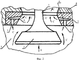
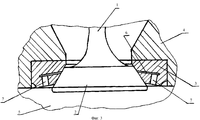
На фиг.1 показана часть газораспределительного механизма, когда головка вошла в контакт с седлом, на фиг.2, когда клапан открыт; на фиг.3, когда головка клапана достигла положения полного прикрытия проходного сечения и упруго деформировала его седло.Figure 1 shows a part of the gas distribution mechanism when the head came into contact with the seat; figure 2, when the valve is open; figure 3, when the valve head has reached the position of full cover passage and elastically deformed its seat.
Газораспределительный механизм состоит из стержня 1 и головки 2 клапана, взаимодействующего с седлом 3, установленным в крышке 4, примыкающей к полости цилиндра 5. В седле 3 выполнен круговой паз 6 с изменяющейся шириной в радиальном направлении его от «В» к «b», и взаимосвязанный с клапанами 7, контактирующими с полостью цилиндра 5.The gas distribution mechanism consists of a rod 1 and a
Работает газораспределительный механизм следующим образом. Когда происходит очистка полости цилиндра 5 от выхлопных газов и поршень начинает движение из н.м.т. вверх по стрелке А (работа, например, двухтактного двигателя 14Д40 подробно описана в книге, представленной в описании прототипа) и клапан является открытым (см. фиг.2), пропуская отработанные газы, которые протекают по стрелкам С не только в пространстве зоны, образованной головкой 2 и стержнем 1 клапана, но и по клапанам 7 и круговом пазу 6 седла 3. Увеличение проходной зоны отработанных газов через указанные элементы способствует лучшей очистке полости цилиндра 5 от отработанных газов. Как только поршень (он на чертежах не показан) переместится по стрелке А до определенного положения, клапан закрывается и принимает такое состояние, как это показано на фиг.1. В этом случае проход рабочей смеси в выхлопное пространство 4 цилиндра 5 прекращается, так как клапан своей головкой 2 плотно садится в седло 3, перекрывая также его каналы 7 и круговой паз 6. Следует отметить, что контакт головки 2 клапана с седлом 3 в серийных конструкциях газораспределительных механизмов происходит резко с возникновением ударной нагрузки в этой зоне. Однако в предлагаемой конструкции такие ударные нагрузки демпфируется за счет упругой деформации части седла 3, которая происходит при уменьшении размера «В» кругового паза 6 так, как это показано на фиг.3. Такие упругие деформации части седла 3 возможны за счет применения для него материалов, обладающих не только жаропрочными, но и упругими свойствами. Деформирующая способность седла 3 увеличивается не только за счет наличия кругового паза 6, обеспечивающего его податливость в направлении стрелки А, но и за счет того, что в нем расположена газовая смесь, находящаяся под высоким давлением, создаваемым поршнем, перемещающимся в В.М.Т. После перехода В.М.Т. поршень двигается в противоположную сторону и в конце рабочего его хода клапан занимает такое положение, как это показано на фиг.2. Далее процесс работы газораспределительного механизма многократно повторяется, подобно тому, как это описано выше.The gas distribution mechanism operates as follows. When there is a cleaning of the cavity of the
Технико-экономическое преимущество предложенного технического решения в сравнении с известными очевидно, так как оно направлено на снижение ударных нагрузок, возникающих в зоне контакта головок клапанов с седлами, что в итоге позволит повысить эксплутационную надежность двигателей внутреннего сгорания.The technical and economic advantage of the proposed technical solution in comparison with the known ones is obvious, since it is aimed at reducing the shock loads arising in the contact zone of the valve heads with seats, which ultimately will increase the operational reliability of internal combustion engines.
Claims (1)
Priority Applications (1)
| Application Number | Priority Date | Filing Date | Title |
|---|---|---|---|
| RU2007115356/06A RU2341663C1 (en) | 2007-04-23 | 2007-04-23 | Valve gear |
Applications Claiming Priority (1)
| Application Number | Priority Date | Filing Date | Title |
|---|---|---|---|
| RU2007115356/06A RU2341663C1 (en) | 2007-04-23 | 2007-04-23 | Valve gear |
Publications (1)
| Publication Number | Publication Date |
|---|---|
| RU2341663C1 true RU2341663C1 (en) | 2008-12-20 |
Family
ID=40375231
Family Applications (1)
| Application Number | Title | Priority Date | Filing Date |
|---|---|---|---|
| RU2007115356/06A RU2341663C1 (en) | 2007-04-23 | 2007-04-23 | Valve gear |
Country Status (1)
| Country | Link |
|---|---|
| RU (1) | RU2341663C1 (en) |
Citations (6)
| Publication number | Priority date | Publication date | Assignee | Title |
|---|---|---|---|---|
| FR1397161A (en) * | 1963-08-24 | 1965-04-30 | Moteur Moderne Le | Device for improving filling in reciprocating machines, in particular in internal combustion engines |
| US3653368A (en) * | 1968-12-14 | 1972-04-04 | Daimler Benz Ag | Valve chamber for the inlet valve of a four-cycle internal combustion engine |
| US4407242A (en) * | 1979-09-08 | 1983-10-04 | Massey-Ferguson-Perkins Limited | Valve seats |
| DE3226439A1 (en) * | 1982-07-15 | 1984-01-19 | Rudolf W. Ing.(grad.) 7056 Weinstadt Gürtler | Intake/exhaust valve for internal combustion engines |
| SU1726794A1 (en) * | 1989-05-29 | 1992-04-15 | Запорожский машиностроительный институт им.В.Я.Чубаря | Valve members of internal combustion engine valve timing |
| RU2242620C2 (en) * | 2000-07-18 | 2004-12-20 | Ман Б Энд В Диесель А/С | Gas exchange valve system |
-
2007
- 2007-04-23 RU RU2007115356/06A patent/RU2341663C1/en not_active IP Right Cessation
Patent Citations (6)
| Publication number | Priority date | Publication date | Assignee | Title |
|---|---|---|---|---|
| FR1397161A (en) * | 1963-08-24 | 1965-04-30 | Moteur Moderne Le | Device for improving filling in reciprocating machines, in particular in internal combustion engines |
| US3653368A (en) * | 1968-12-14 | 1972-04-04 | Daimler Benz Ag | Valve chamber for the inlet valve of a four-cycle internal combustion engine |
| US4407242A (en) * | 1979-09-08 | 1983-10-04 | Massey-Ferguson-Perkins Limited | Valve seats |
| DE3226439A1 (en) * | 1982-07-15 | 1984-01-19 | Rudolf W. Ing.(grad.) 7056 Weinstadt Gürtler | Intake/exhaust valve for internal combustion engines |
| SU1726794A1 (en) * | 1989-05-29 | 1992-04-15 | Запорожский машиностроительный институт им.В.Я.Чубаря | Valve members of internal combustion engine valve timing |
| RU2242620C2 (en) * | 2000-07-18 | 2004-12-20 | Ман Б Энд В Диесель А/С | Gas exchange valve system |
Similar Documents
| Publication | Publication Date | Title |
|---|---|---|
| US7377249B1 (en) | Outward-opening gas-exchange valve system for an internal combustion engine | |
| HRP960412A2 (en) | A piston ring for a piston in an internal combustion engine | |
| US9915222B2 (en) | Diesel piston with semi-hemispherical crown | |
| US9470177B2 (en) | Cylinder head for internal combustion engine | |
| CN108291459B (en) | engine valve | |
| FI123409B (en) | Throttle valve arrangement and cylinder cover | |
| CN108350803B (en) | Compact Ported Cylinder Construction for Opposed Piston Engines | |
| RU2341663C1 (en) | Valve gear | |
| US20160090938A1 (en) | Internal Combustion Engine Cylinder Flow Deflector | |
| US7438036B2 (en) | Oil metering valve seal | |
| US8360395B2 (en) | Sliding valve assembly | |
| US3334618A (en) | Four stroke high r.p.m. internal combustion engine for racing purposes | |
| US20170089224A1 (en) | Rocker base for valve actuation system | |
| RU2390638C1 (en) | Valve gear | |
| US9297332B2 (en) | Cylinder head with annular valve for internal-combustion engine | |
| RU2343295C1 (en) | Gas-distributing mechanism | |
| RU2403408C1 (en) | Valve gear | |
| RU2397335C1 (en) | Ice valve gear | |
| RU2397336C1 (en) | Diesel engine valve gear | |
| RU2472009C1 (en) | Gas-distributing mechanism | |
| RU2567482C2 (en) | Diesel engine valve gear | |
| CA2383673A1 (en) | Valve seal assembly module with spring and retainers | |
| RU2316655C1 (en) | Mechanism of gas distributing | |
| Holt | The diesel engine | |
| RU2502881C1 (en) | Ice timing gear valve |
Legal Events
| Date | Code | Title | Description |
|---|---|---|---|
| MM4A | The patent is invalid due to non-payment of fees |
Effective date: 20120424 |