Изобретение относится к области двигателей внутреннего сгорания и может быть использовано как в конструкциях четырехтактных карбюраторных двигателей, так и дизелей.The invention relates to the field of internal combustion engines and can be used both in the design of four-stroke carburetor engines and diesel engines.
Известен механизм газораспределения, используемый в конструкции карбюраторного двигателя, описанный и показанный на стр.42-43, рис.43 в книге Стеблева Н.М. "Современный автомобиль". Издательство ДОСААФ. - М., 1955 г. Такой механизм состоит из впускного и выпускного клапанов, каждый из которых выполнен в виде стержня, плавно переходящего в головку, и последняя по своей образующей снабжена рабочей поверхностью, взаимодействующей с седлом клапана, запрессованным в блок цилиндров двигателя внутреннего сгорания. Каждый из клапанов подпружинен относительно блока цилиндров и управляется с помощью толкателей, взаимодействующих с распределительным валом ДВС. С помощью клапанов за четыре хода движения поршня происходят заполнение цилиндров горючей смесью, ее сжатие, горение и расширение и выпуск отработанных газов. Заполнение горючей смесью происходит из всасывающего коллектора, расположенного в блоке цилиндров, а выпуск отработанных газов - в выхлопной коллектор. Несмотря на свою эффективность использования такой механизм газораспределения обладает существенным недостатком, заключающимся в том, что всасывание горючей смеси и удаление из цилиндров отработанных газов происходит через узкие щели, расположенные между седлами клапанов и внешними образующими поверхностями клапанных головок. Такое явление снижает эффективность заполнения горючей смесью полости цилиндра при всасывании и "очистку" этого же объема от отработанных газов, а также способствует неравномерному распределению температуры по всему объему головки клапана.The known gas distribution mechanism used in the design of the carburetor engine, described and shown on pages 42-43, Fig. 43 in the book of N. Steblev "Modern car." Publisher DOSAAF. - M., 1955. Such a mechanism consists of inlet and outlet valves, each of which is made in the form of a rod that smoothly passes into the head, and the latter is provided with a working surface in its generatrix interacting with the valve seat, pressed into the cylinder block of the internal combustion engine . Each of the valves is spring-loaded relative to the cylinder block and is controlled by pushers interacting with the ICE camshaft. Using valves for four strokes of the movement of the piston, the cylinders are filled with a combustible mixture, compressed, burned, expanded, and exhausted. Filling with a combustible mixture occurs from the intake manifold located in the cylinder block, and the exhaust gas is discharged into the exhaust manifold. Despite its efficiency of use, such a gas distribution mechanism has a significant drawback, namely, that the intake of a combustible mixture and removal of exhaust gases from cylinders occurs through narrow slots located between the valve seats and the external forming surfaces of the valve heads. This phenomenon reduces the efficiency of filling with a combustible mixture of the cylinder cavity during suction and "cleaning" the same volume of exhaust gases, and also contributes to the uneven distribution of temperature throughout the volume of the valve head.
Известен также механизм газораспределения ДВС, описанный в книге Корягина А.В. и Соловьева Г.М. Устройство, обслуживание и правила движения автомобилей. Военное издательство МО СССР. - М., 1960 г., стр.56-57 и показанный на рис.29. Конструкция такого механизма газораспределения аналогична вышеописанной и поэтому недостатки их подобны.The gas distribution mechanism of the internal combustion engine is also known, described in the book by A.V. and Soloviev G.M. The device, service and traffic rules of cars. Military publishing house of the Ministry of Defense of the USSR. - M., 1960, pp. 56-57 and shown in Fig. 29. The design of such a gas distribution mechanism is similar to that described above and therefore their disadvantages are similar.
Поэтому задачей изобретения является повышение эффективности работы механизма газораспределения ДВС за счет увеличения проходных сечений впускного и выпускного клапанов, через которые в цилиндры поступает горючая смесь и удаляются из него отработанные газы, а также равномерного распределения теплового поля по всему объему головок клапанов.Therefore, the object of the invention is to increase the efficiency of the engine gas distribution mechanism by increasing the inlet and exhaust valve cross-sections through which the combustible mixture enters the cylinders and exhaust gases are removed from it, as well as the uniform distribution of the thermal field over the entire volume of the valve heads.
Поставленная задача достигается тем, что впускной и выпускной клапаны каждого из цилиндров блока в своих головках снабжены наклонными в вертикальной их плоскости каналами, начало которых находится на торцевой части головок, а концы - на их рабочей поверхности, причем начала и концы упомянутых каналов выполнены различного диаметра и большие из них расположены на внешних торцевых частях головок клапанов, а меньшие - на их рабочих поверхностях.The problem is achieved in that the inlet and outlet valves of each of the cylinders of the block in their heads are equipped with channels inclined in their vertical plane, the beginning of which is located on the end part of the heads, and the ends are on their working surface, and the beginning and ends of the said channels are made of different diameters and the larger ones are located on the outer end parts of the valve heads, and the smaller ones on their working surfaces.
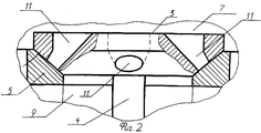
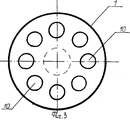
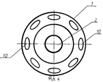
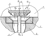
На фиг.1 показан общий вид механизма газораспределения с разрезом сбоку, на фиг.2 - часть одного из его клапанов с вырывами, на фиг.3 - вид клапана сверху, на фиг.4 - вид клапана снизу и на фиг.5 - один из моментов открытия клапана.Figure 1 shows a General view of the gas distribution mechanism with a side cut, figure 2 is a part of one of its valves with tears, figure 3 is a top view of the valve, figure 4 is a bottom view of the valve, and figure 5 is one of valve opening times.
Механизм газораспределения состоит из впускного клапана, выполненного за одно целое с головкой 1 и стержнем 2, и выпускного клапана, содержащего головку 3 и стержень 4. Головки 1 и 3 клапанов контактируют с седлами 5, запрессованными в блок цилиндров 6, включающий в себя камеру сгорания 7, впускной коллектор 8 и выхлопной коллектор 9. Головки 1 и 3 клапанов имеют сквозные каналы соответственно 10 и 11. Головки 1 и 3 клапана имеют рабочую поверхность 12.The gas distribution mechanism consists of an inlet valve made integral with the head 1 and the rod 2, and an exhaust valve containing the head 3 and the rod 4. The valve heads 1 and 3 are in contact with the seats 5, pressed into the cylinder block 6, which includes a combustion chamber 7, the intake manifold 8 and the exhaust manifold 9. The valve heads 1 and 3 have through channels 10 and 11, respectively. The valve heads 1 and 3 have a working surface 12.
Работает механизм газораспределения следующим образом. Для заполнения камеры сгорания 7 горючей смесью, находящейся в впускном коллекторе 8, широко известными в технике способами впускной клапан с головками 1 и стержнем 2 перемещается по стрелке А и горючая смесь за счет разрежения, создаваемого поршнем, находящимся в цилиндре блока 6 (цилиндр и поршень на чертеже не показаны, но работа ДВС подробно описана в книге Стеблева Н.М., которая выбрана в качестве аналога, где в ней представлены четыре такта его работы и использующего в качестве топлива бензин), через щели, образованные между головкой 1 и седлом 5, по стрелке В (см. фиг.5) поступает в камеру сгорания 7. В то же время как только головка клапана приподнимется по стрелке А над седлом 5, сквозные каналы 10 окажутся открытыми (как это показано на фиг.5) и через них так же, как и в предыдущем случае, по стрелке В горючая смесь поступит в камеру сгорания 7. После этого, как только поршень достигнет нижней мертвой точки, всасывающий клапан с головкой 1 и стержнем 2 перемещается в направлении, обратном стрелке А, и занимает положение, показанное на фиг.1, тем самым плотно примыкая своей рабочей поверхностью 12 к седлу 5 прикрывает каналы 10. Далее осуществляется процесс сжатия и поршень доходит до своей верхней мертвой точки. Как это произойдет, широко известным способом горючая смесь воспламеняется, а так как оба клапана закрыты, то поршень под действием создавшегося давления газов перемещается в сторону нижней мертвой точки, то есть происходит его рабочий ход. Перейдя вновь нижнюю мертвую точку, поршень в последующем перемещается вверх и выпускной клапан с головкой 3 и стержнем 4, подобно тому, как это показано, например, на фиг.5, открывается по стрелке С и газы проходят из камеры сгорания 7 в щели, образованные им с седлом 5, а также через каналы 11, но только в направлении, обратном стрелкам В, поступая в выхлопной коллектор 9, выбрасываются в атмосферу. Как только поршень перейдет верхнюю мертвую точку, выпускной клапан своей головкой 3 поджимается к седлу 5, в этот момент времени по стрелке А впускной клапан вновь открывается и происходит процесс, аналогичный описанному выше.The gas distribution mechanism works as follows. To fill the combustion chamber 7 with a combustible mixture, located in the intake manifold 8, by the methods well known in the art, the inlet valve with the heads 1 and the rod 2 moves along arrow A and the combustible mixture due to the vacuum created by the piston located in the cylinder of the block 6 (cylinder and piston not shown in the drawing, but the operation of the internal combustion engine is described in detail in the book by N. M. Steblev, which is selected as an analogue, where it shows four cycles of its operation and uses gasoline as fuel) through the slots formed between head 1 and c length 5, along arrow B (see FIG. 5) enters combustion chamber 7. At the same time, as soon as the valve head rises along arrow A along seat 5, the through channels 10 will be open (as shown in FIG. 5) and through them, as in the previous case, along arrow B, the combustible mixture enters the combustion chamber 7. After this, as soon as the piston reaches bottom dead center, the suction valve with head 1 and rod 2 moves in the opposite direction to arrow A, and occupies the position shown in figure 1, thereby tightly adjoining its working turn By means of a 12 to the saddle 5 it covers the channels 10. Next, the compression process is carried out and the piston reaches its top dead center. As this happens, in a well-known way, the combustible mixture is ignited, and since both valves are closed, the piston moves under the influence of the generated gas pressure towards the bottom dead center, that is, its working stroke occurs. Crossing again the bottom dead center, the piston subsequently moves upward and the exhaust valve with head 3 and rod 4, similar to that shown, for example, in Fig. 5, opens along arrow C and gases pass from the combustion chamber 7 into the slots formed them with a saddle 5, as well as through channels 11, but only in the direction opposite to arrows B, entering the exhaust manifold 9, are released into the atmosphere. As soon as the piston crosses the top dead center, the exhaust valve with its head 3 is pressed against the seat 5, at this moment in time, along the arrow A, the intake valve opens again and a process similar to that described above occurs.
Технико-экономическое преимущество предложенного технического решения в сравнении с известными очевидно, так как, во-первых, за счет наличия отверстий выполненных в головках 1 и 3 и рабочих поверхностях 12 впускного и выпускного клапанов увеличивается производительность подачи горючей смеси или удаления отработанных газов в камеру сгорания двигателя или из нее и, во-вторых, высокие температуры, характерные для этого механизма, возникающие в процессе сжигания рабочей смеси, равномерно распределяются по всему объему головок клапанов, что в итоге позволяет повысить долговечность последних особенно в зонах сопряжения их рабочих поверхностей с гнездами. Все это в итоге позволит получить соответствующий экономический эффект при эксплуатации ДВС.The technical and economic advantage of the proposed technical solution in comparison with the known ones is obvious, because, firstly, due to the presence of holes made in the heads 1 and 3 and the working surfaces 12 of the inlet and outlet valves, the productivity of supplying a combustible mixture or removing exhaust gases into the combustion chamber is increased engine or from it and, secondly, the high temperatures characteristic of this mechanism that occur during the combustion of the working mixture are evenly distributed over the entire volume of the valve heads, which ultimately enhances the durability of the latter particularly in the areas of coupling of their working surfaces with the slots. All this ultimately will allow you to get the corresponding economic effect in the operation of ICE.