RU2335577C2 - Sealing lock for line of vacuum application of coating on continuously stretched metal tape - Google Patents
Sealing lock for line of vacuum application of coating on continuously stretched metal tape Download PDFInfo
- Publication number
- RU2335577C2 RU2335577C2 RU2005137556/02A RU2005137556A RU2335577C2 RU 2335577 C2 RU2335577 C2 RU 2335577C2 RU 2005137556/02 A RU2005137556/02 A RU 2005137556/02A RU 2005137556 A RU2005137556 A RU 2005137556A RU 2335577 C2 RU2335577 C2 RU 2335577C2
- Authority
- RU
- Russia
- Prior art keywords
- rolls
- tape
- pair
- rollers
- chamber
- Prior art date
Links
Images


Classifications
-
- B—PERFORMING OPERATIONS; TRANSPORTING
- B29—WORKING OF PLASTICS; WORKING OF SUBSTANCES IN A PLASTIC STATE IN GENERAL
- B29C—SHAPING OR JOINING OF PLASTICS; SHAPING OF MATERIAL IN A PLASTIC STATE, NOT OTHERWISE PROVIDED FOR; AFTER-TREATMENT OF THE SHAPED PRODUCTS, e.g. REPAIRING
- B29C37/00—Component parts, details, accessories or auxiliary operations, not covered by group B29C33/00 or B29C35/00
- B29C37/0025—Applying surface layers, e.g. coatings, decorative layers, printed layers, to articles during shaping, e.g. in-mould printing
-
- C—CHEMISTRY; METALLURGY
- C23—COATING METALLIC MATERIAL; COATING MATERIAL WITH METALLIC MATERIAL; CHEMICAL SURFACE TREATMENT; DIFFUSION TREATMENT OF METALLIC MATERIAL; COATING BY VACUUM EVAPORATION, BY SPUTTERING, BY ION IMPLANTATION OR BY CHEMICAL VAPOUR DEPOSITION, IN GENERAL; INHIBITING CORROSION OF METALLIC MATERIAL OR INCRUSTATION IN GENERAL
- C23C—COATING METALLIC MATERIAL; COATING MATERIAL WITH METALLIC MATERIAL; SURFACE TREATMENT OF METALLIC MATERIAL BY DIFFUSION INTO THE SURFACE, BY CHEMICAL CONVERSION OR SUBSTITUTION; COATING BY VACUUM EVAPORATION, BY SPUTTERING, BY ION IMPLANTATION OR BY CHEMICAL VAPOUR DEPOSITION, IN GENERAL
- C23C14/00—Coating by vacuum evaporation, by sputtering or by ion implantation of the coating forming material
- C23C14/22—Coating by vacuum evaporation, by sputtering or by ion implantation of the coating forming material characterised by the process of coating
- C23C14/56—Apparatus specially adapted for continuous coating; Arrangements for maintaining the vacuum, e.g. vacuum locks
- C23C14/562—Apparatus specially adapted for continuous coating; Arrangements for maintaining the vacuum, e.g. vacuum locks for coating elongated substrates
Abstract
Description
Предмет изобретенияSubject of invention
[0001] Настоящее изобретение относится к усовершенствованному входному и/или выходному уплотнительному затвору линии вакуумного нанесения тонкого слоя на движущееся плоское изделие, предпочтительно металлическую ленту (из углеродистой стали, нержавеющей стали и пр.).[0001] The present invention relates to an improved inlet and / or outlet seal of a vacuum line for applying a thin layer to a moving flat article, preferably a metal strip (carbon steel, stainless steel, etc.).
Уровень техникиState of the art
[0002] Внутри камеры вакуумного нанесения покрытий (давление порядка 10-5 мбар) могут осуществляться самые разнообразные процессы - чистка, напыление и т.п.[0002] Inside the chamber of vacuum coating (pressure of the order of 10 -5 mbar), a variety of processes can be carried out - cleaning, spraying, etc.
[0003] Как в черной, так и в цветной металлургии линии для непрерывного вакуумного нанесения металлических (из чистого металла, сплавов, оксидов) или органических покрытий представляют для специалистов все больший интерес по целому ряду причин.[0003] In both ferrous and non-ferrous metallurgy, lines for the continuous vacuum deposition of metal (from pure metal, alloys, oxides) or organic coatings are of increasing interest to specialists for a number of reasons.
[0004] Прежде всего, такие линии значительно облегчают разработку новой продукции. На сегодняшний день технологии выполнения покрытий на стальных лентах ограничены в промышленном масштабе процессами окунания или электролитического осаждения, которые представляют собой традиционные способы. Количество получаемых таким путем изделий оказывается чрезвычайно ограниченным. Промышленное внедрение линий вакуумного нанесения покрытий, принцип действия которых в настоящее время уже полностью освоен на опытных производствах, способствовало бы разработке десятков новых разновидностей продукции.[0004] First of all, such lines greatly facilitate the development of new products. To date, the technology for making coatings on steel strips is limited on an industrial scale by dipping or electrolytic deposition processes, which are traditional methods. The number of products obtained in this way is extremely limited. The industrial introduction of vacuum coating lines, the operating principle of which has now been fully mastered in pilot production, would facilitate the development of dozens of new varieties of products.
[0005] Кроме того, если говорить об охране окружающей среды, то, если технологию выполнения покрытий методом окунания можно считать экологически чистой (за исключением нанесения матирующих покрытий), при электролитическом осаждении требуется проведение таких дополнительных операций химической обработки, как фильтрация, регенерация, очистка шламов и пр. Во всех этих случаях подготовка поверхности сопровождается появлением подлежащих обработке жидких отходов в виде растворов и шламов. Что же касается вакуумного нанесения покрытий, будь то с использованием или без использования плазмы, то оно, напротив, представляет собой сухой процесс. Здесь требуется лишь извлечение сухих отходов, образовавшихся при очистке поверхностей и при нанесении на поверхность материала.[0005] In addition, if we talk about environmental protection, then, if the technology of making coatings by dipping can be considered environmentally friendly (except for the application of matting coatings), electrolytic deposition requires additional chemical processing operations such as filtration, regeneration, and cleaning sludge, etc. In all these cases, surface preparation is accompanied by the appearance of the liquid waste to be treated in the form of solutions and sludge. As for vacuum coating, whether with or without plasma, it is, on the contrary, a dry process. It only requires the extraction of dry waste generated by cleaning surfaces and when applied to the surface of the material.
[0006] Известны уплотнительные затворы, предназначенные для изоляции камеры вакуумного нанесения покрытий от остальных компонентов линии - таких, как разматыватель, моталка и др. Затвор - это такой компонент, регулировка которого исключительно важна на этапе промышленного внедрения. Различные конструкции затворов описаны в ряде известных документов: US-A-3158507, US-A-3367667, US-A-3467399, US-A-3868106, US-A-4501428, US-A-5000114, EP-A-0535568, US-A-5842855, US-A-5865932. Наиболее близкий аналог раскрыт в патентном документе ЕР 1004369 А, С23С 14/56, 31.05.2000. Однако эти технические решения в своем большинстве так и не позволили добиться эффективного промышленного внедрения.[0006] There are known sealing gates designed to isolate the vacuum coating chamber from other components of the line — such as an uncoiler, coiler, etc. A shutter is a component whose adjustment is extremely important at the industrial implementation stage. Various gate designs are described in a number of well-known documents: US-A-3158507, US-A-3367667, US-A-3467399, US-A-3868106, US-A-4501428, US-A-5000114, EP-A-0535568 US-A-5842855; US-A-5865932. The closest analogue is disclosed in patent document EP 1004369 A, C23C 14/56, 05/31/2000. However, these technical solutions for the most part did not allow achieving an effective industrial implementation.
[0007] Чаще всего для предотвращения утечек, имеющих место в таких слабых местах, какими являются входной или выходной затвор, применения этих устройств стараются избегать. В стекольном производстве выполняют пакетное нанесение покрытий на плиты стандартных размеров, а в производстве пластмассовых изделий применяют технику намотки в самой вакуумной камере.[0007] Most often, in order to prevent leaks occurring in such weak places as the input or output gate, they try to avoid using these devices. In the glass industry, batch coating of plates of standard sizes is performed, and in the production of plastic products, the winding technique in the vacuum chamber itself is used.
[0008] На фиг.1 приведен пример входного/выходного затвора 5 для камеры вакуумного нанесения покрытий. Как видно на чертеже, девять валков 10, 11, 12,... расположены в шахматном порядке и ограничивают субкамеры 20, 21, 22,... Каждая из субкамер связана с системой откачки 3. Совокупность систем откачки 3 обеспечивает возможность получения последовательного, субкамера за субкамерой, разрежения, при этом в последней субкамере вакуум может достигать 10-5 мбар. Указанное расположение в шахматном порядке позволяет уменьшить количество валков, что делает затвор менее громоздким. Кроме того, проходя по валкам, лента изгибается в виде дуги, что позволяет добиться надежного уплотнения по ширине ленты, которое оказывается существенно больше, нежели в случае, когда она находится просто в зазоре между валками. Таким образом, становится вполне приемлемым больший зазор между двумя валками.[0008] Figure 1 shows an example of an input /
[0009] Следует также отметить, что каждый валок расположен на опоре, прикрепленной к горизонтальной стенке камеры, обращенной к этому валку, в зависимости от обстоятельств, нижней или верхней. Здесь зона утечки сокращается до зазора между валком и опорой. Остаются также утечки между боковыми сторонами цилиндрических валков и боковыми стенками камеры.[0009] It should also be noted that each roll is located on a support attached to a horizontal wall of the chamber facing this roll, depending on the circumstances, lower or upper. Here, the leakage zone is reduced to a gap between the roll and the support. There are also leaks between the sides of the cylindrical rolls and the side walls of the chamber.
[0010] Наконец, для сохранения уплотнения в каждой субкамере необходимо, чтобы контактное давление между лентой и валками, обеспечивающее уплотнение субкамеры, было, по меньшей мере, равным разности давлений между указанной субкамерой и окружающим ее пространством. В противном случае существует опасность отрыва ленты от валка. Во избежание этого явления следует приложить к ленте растягивающее усилие, которое было бы достаточным для компенсации разности давлений, имеющей место между двумя следующими друг за другом субкамерами.[0010] Finally, in order to maintain a seal in each subchamber, it is necessary that the contact pressure between the tape and the rolls, providing a seal for the subchamber, is at least equal to the pressure difference between the subchamber and its surrounding space. Otherwise, there is a danger of the tape coming off the roll. To avoid this phenomenon, a tensile force should be applied to the tape, which would be sufficient to compensate for the pressure difference occurring between two successive subchambers.
[0011] Для промышленного внедрения в случае непрерывного протягивания приходится разрешить ряд проблем, свойственных современному уровню техники. Прежде всего, возникает проблема возможности легкого обслуживания оборудования. Необходимо обеспечить возможность легкого ввода ленты в затвор. Кроме того, кожух, образующий вакуумную камеру, имеет ограниченную высоту, и, следовательно, доступ к нему затруднен. При современном уровне техники в случае, если понадобится, например, проверить состояние поверхностей валков, камеру придется полностью демонтировать. Существует еще одна проблема, связанная с потерей вакуума, которая обусловлена имеющими место в затворе утечками, что приводит к снижению производительности откачки. Следствием этого являются значительное потребление электроэнергии и необходимость увеличения затрат на откачивающее оборудование.[0011] For industrial implementation in the case of continuous pulling, it is necessary to solve a number of problems inherent in the state of the art. First of all, the problem arises of the possibility of easy equipment maintenance. It must be possible to easily insert the tape into the shutter. In addition, the casing forming the vacuum chamber has a limited height, and therefore access to it is difficult. With the current state of the art, if it is necessary, for example, to check the condition of the surfaces of the rolls, the camera will have to be completely dismantled. There is another problem associated with the loss of vacuum, which is caused by leaks occurring in the gate, which leads to a decrease in pumping performance. The consequence is significant energy consumption and the need to increase the cost of pumping equipment.
[0012] По определению, происходящий под вакуумом части кожуха теплообмен либо вообще отсутствует, либо недостаточен, чтобы вызвать расширение валков в части, находящейся под вакуумом. По сути, одного лишь контакта недостаточно для обеспечения теплопроводности между горячей лентой и валками, находящимися на стороне вакуума. С другой стороны, имеет место обусловленное теплообменом расширение валков на стороне воздуха, которое может в некоторых случаях доходить до наружной оболочки кожуха. Такое расширение валков по длине приводит к возрастанию опасности заедания вследствие их соприкосновения с боковыми стенками камеры. Дело в том, что деформацию не повторяет наружная часть кожуха, находящаяся на стороне воздуха, в той мере, в какой она жестко связана с его частью, находящейся на стороне вакуума, которая не расширяется.[0012] By definition, the heat exchange occurring under the vacuum of the casing portion is either absent altogether or insufficient to cause rolls to expand in the vacuum portion. In fact, contact alone is not enough to ensure thermal conductivity between the hot tape and the rolls located on the vacuum side. On the other hand, there is an expansion of the rolls caused by heat exchange on the air side, which in some cases can reach the outer shell of the casing. Such expansion of the rolls along the length leads to an increase in the risk of seizing due to their contact with the side walls of the chamber. The fact is that the deformation is not repeated by the outer part of the casing located on the side of the air, in so far as it is rigidly connected with its part located on the side of the vacuum, which does not expand.
Цели изобретенияOBJECTS OF THE INVENTION
[0013] Целью изобретения является создание такого входного/выходного уплотнительного затвора линии вакуумного нанесения покрытия на плоское изделие, который был бы свободен от недостатков, свойственных конструкциям, известным из уровня техники.[0013] An object of the invention is to provide an inlet / outlet seal for a vacuum coating line of a flat article that is free from the drawbacks inherent in prior art structures.
[0014] Предметом изобретения является, в частности, уплотнительный затвор, который можно было бы использовать в линии непрерывного вакуумного нанесения покрытий на плоское металлическое изделие типа ленты из углеродистой или нержавеющей стали.[0014] A subject of the invention is, in particular, a sealing valve that could be used in a continuous vacuum coating line on a flat metal product such as a strip of carbon or stainless steel.
[0015] Дополнительной целью изобретения является создание затвора с возможностью легкого обслуживания (легкий ввод ленты, свободный доступ к валкам и пр.).[0015] An additional object of the invention is to provide a shutter with easy maintenance (easy tape insertion, easy access to the rolls, etc.).
[0016] Следующая цель изобретения состоит в создании затвора, позволяющего получить более высокую производительность откачки, с одновременным снижением потребления требуемой для этого электроэнергии и сведением к минимуму необходимого оборудования.[0016] A further object of the invention is to provide a shutter capable of obtaining higher pumping performance, while reducing the energy consumption required for this and minimizing the necessary equipment.
[0017] Еще одна цель изобретения - предотвращение опасности заедания валков, вызываемой расширением металлических узлов, частично работающих в вакууме.[0017] Another objective of the invention is the prevention of the danger of jamming of the rolls caused by the expansion of metal nodes, partially working in a vacuum.
[0018] Наконец, целью изобретения является предотвращение преимущественного износа валков, снабженных дополнительным резиновым покрытием.[0018] Finally, an object of the invention is to prevent the predominant wear of rolls provided with an additional rubber coating.
Сущность изобретенияSUMMARY OF THE INVENTION
[0019] Первый объект настоящего изобретения - уплотнительный затвор для камеры вакуумного нанесения покрытия на непрерывно протягиваемую предпочтительно металлическую ленту, имеющий съемные нижнюю и верхнюю крышки и содержащий ряд пар металлических валков, между которыми проходит лента и удерживаемых на опоре, прикрепленной к обращенной к ней крышке, с зазором, определяющим зону первой утечки, причем две следующие друг за другом пары валков ограничивают субкамеру, в которой поддерживают заданное давление ниже атмосферного с помощью установки откачки, соединенной с указанной камерой, отличающийся тем, что:[0019] The first object of the present invention is a sealing shutter for a vacuum coating chamber for a continuously stretched preferably metal tape having removable lower and upper covers and containing a series of pairs of metal rolls between which the tape passes and are held on a support attached to the cover facing thereto , with a gap defining the zone of the first leak, moreover, two successive pairs of rolls define a sub-chamber in which the set pressure is maintained below atmospheric by means of a mouth new pumping connected to the specified camera, characterized in that:
- валки установлены на подшипниках, жестко связанных с указанными крышками, и выполнены также съемными;- the rolls are mounted on bearings rigidly connected with said covers and are also removable;
- оси валков одной пары расположены в общей вертикальной плоскости, и эти валки имеют разные диаметры, причем положение валка меньшего диаметра оказывается поочередно верхним и нижним при переходе от одной отдельной пары валков к смежной с ней паре;- the axis of the rolls of one pair are located in a common vertical plane, and these rolls have different diameters, and the position of the roll of a smaller diameter is alternately upper and lower in the transition from one separate pair of rolls to an adjacent pair;
- опоры для удержания двух валков одной пары имеют сбоку выступ в сторону центра, зазор которого относительно боковой поверхности указанных валков определяет зону второй утечки.- supports for holding two rolls of the same pair have a side protrusion towards the center, the gap of which relative to the side surface of these rolls defines the zone of the second leak.
[0020] В соответствии с одним из предпочтительных вариантов осуществления изобретения валки меньшего диаметра покрыты слоем резины или эластомера определенной толщины.[0020] In accordance with one preferred embodiment of the invention, the rolls of smaller diameter are coated with a layer of rubber or elastomer of a certain thickness.
[0021] Целесообразно такое выполнение валков большего диаметра, чтобы поверхности их контакта с лентой были металлическими и определяли путь прохождения ленты.[0021] It is advisable that the rolls of larger diameter be made such that their contact surfaces with the tape are metallic and determine the path of the tape.
[0022] В соответствии с другим предпочтительным вариантом осуществления валки одной и той же пары смещены в поперечном направлении относительно движения ленты, так что на каждой боковой стороне затвора один из валков выступает относительно другого валка.[0022] According to another preferred embodiment, the rolls of the same pair are laterally offset relative to the movement of the tape, so that on each side of the shutter one of the rolls protrudes relative to the other roll.
[0023] Целесообразно, чтобы было обеспечено уплотнение каждой субкамеры затвора между лентой и корпусами обоих валков посредством предварительного прижима валка, покрытого резиной, к валку с металлической поверхностью, что обеспечивает одновременно прохождение ленты и обжатие резины или эластомера вокруг ленты.[0023] It is advisable that each shutter sub-chamber be sealed between the tape and the housings of both rolls by pre-clamping the rubber-coated roll to the roll with a metal surface, which allows the passage of the tape and the compression of the rubber or elastomer around the tape.
[0024] Целесообразно также, чтобы угол изменения направления движения ленты определялся отношением диаметров валков одной пары и был менее 10°.[0024] It is also advisable that the angle of change in the direction of movement of the tape was determined by the ratio of the diameters of the rolls of one pair and was less than 10 °.
[0025] Одно из существенных преимуществ изобретения заключается в том, что наименьшее давление в субкамере оказывается меньше 10-4 мбар, предпочтительно 10-5 мбар.[0025] One of the significant advantages of the invention is that the lowest pressure in the subchamber is less than 10 -4 mbar, preferably 10 -5 mbar.
[0026] Предпочтительно, чтобы зазор, определяющий зону первой утечки, зависел от максимальной ширины ленты, зазор, определяющий вторую зону утечки, был практически постоянным и составлял менее 0,3 мм, предпочтительно 0,2 мм.[0026] Preferably, the clearance defining the first leakage zone is dependent on the maximum width of the tape, the clearance defining the second leakage zone is substantially constant and is less than 0.3 mm, preferably 0.2 mm.
[0027] Второй объект изобретения - линия вакуумного нанесения тонкого металлического или органического слоя на плоское железное, стальное или металлическое изделие, движущееся со скоростью, по меньшей мере, 10 м/мин, предпочтительно ленту из углеродистой или нержавеющей стали, имеющую входной и/или выходной уплотнительный затвор описанного выше типа.[0027] The second object of the invention is a line for vacuum deposition of a thin metal or organic layer on a flat iron, steel or metal product moving at a speed of at least 10 m / min, preferably a carbon or stainless steel tape having an inlet and / or output sealing shutter of the type described above.
Краткое описание чертежейBrief Description of the Drawings
[0028] На фиг.1, которая уже рассматривалась выше, дан вид в разрезе уплотнительного затвора для камеры вакуумного нанесения покрытий в соответствии с уровнем техники.[0028] Figure 1, which has already been discussed above, is a sectional view of a sealing shutter for a vacuum coating chamber in accordance with the prior art.
[0029] На фиг.2 представлен вид в вертикальном и продольном разрезе уплотнительного затвора для камеры вакуумного нанесения покрытий в соответствии с одним из предпочтительных вариантов выполнения изобретения. Здесь же показаны две съемные крышки.[0029] FIG. 2 is a vertical and longitudinal sectional view of a sealing shutter for a vacuum coating chamber in accordance with one preferred embodiment of the invention. Two removable covers are also shown here.
[0030] На фиг.3 представлен вид сверху уплотнительного затвора для камеры вакуумного нанесения покрытий по фиг.2.[0030] FIG. 3 is a plan view of a sealing shutter for the vacuum coating chamber of FIG. 2.
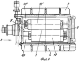
[0031] На фиг.4 представлен вид в вертикальном и поперечном разрезе затвора по фиг.2.[0031] FIG. 4 is a vertical and cross-sectional view of the shutter of FIG. 2.
Описание одного из предпочтительных вариантов осуществления изобретенияDescription of one of the preferred embodiments of the invention
[0032] Фиг.2 и 3 иллюстрируют конкретный пример выполнения входного/выходного затвора для камеры вакуумного нанесения покрытий согласно изобретению. Металлическая лента 1 поступает в затвор слева и выходит из него справа. В данном случае камера 5 содержит четыре пары установленных напротив друг друга валков 10, 10', 11, 11', ..., между которыми размещена лента. Эти пары валков ограничивают субкамеры 20, 21, 22,..., в каждой из которых действуют разные давления, которые в случае, например, с входным затвором последовательно уменьшаются. А в случае с выходным затвором имеет место обратная ситуация.[0032] FIGS. 2 and 3 illustrate a specific example of an input / output shutter for a vacuum coating chamber according to the invention. The metal tape 1 enters the shutter on the left and leaves it on the right. In this case, the
[0033] Согласно изобретению, для того чтобы обеспечить возможность обслуживания камеры и доступ к валкам, предусмотрено выполнение подшипников валков 30, 30',... съемными и жестко связанными с нижней крышкой 6 или верхней крышкой 7 камеры, в зависимости от того, в каком положении находится рассматриваемый валок - нижнем или верхнем. Приняты также меры к тому, чтобы можно было развести на достаточное расстояние в вертикальной плоскости две крышки 6 и 7 с помощью подъемных устройств (не показаны). Благодаря этому в ходе процесса техобслуживания можно легко получить доступ к валкам или к подшипникам. Еще одно преимущество данной конструкции - простота ввода ленты.[0033] According to the invention, in order to provide camera service and access to the rolls, it is envisaged that the roller bearings 30, 30 ', ... are removable and rigidly connected to the
[0034] Для улучшения герметичности камеры на уровне каждой пары валков предусмотрен целый ряд дополнительных элементов.[0034] To improve the tightness of the chamber at the level of each pair of rolls, a number of additional elements are provided.
[0035] Во-первых, валок меньшего диаметра 10', 11', 12',... снабжен, по меньшей мере, по всей своей контактной поверхности резиновым или эластомерным покрытием. Таким образом, в каждой паре валков металлический валок задает линию прохождения ленты, в то время как положение валка с резиновым покрытием изначально регулируют так, чтобы он оказывал достаточное усилие прижима на соответствующий металлический валок с деформацией резины, позволяющей следовать профилю ленты (см. фиг.4). В результате благодаря сдавливанию ленты между резиной и голым металлическим валком обеспечивают уплотнение на поверхности ленты по всей ее ширине, а также по бокам ленты.[0035] First, a roll of smaller diameter 10 ', 11', 12 ', ... is provided with at least a rubber or elastomeric coating over at least its entire contact surface. Thus, in each pair of rolls, the metal roll defines the line of passage of the tape, while the position of the roll with a rubber coating is initially adjusted so that it exerts sufficient clamping force on the corresponding metal roll with the deformation of the rubber, which allows to follow the profile of the tape (see Fig. four). As a result, by squeezing the tape between the rubber and the bare metal roll, they provide a seal on the surface of the tape over its entire width, as well as on the sides of the tape.
[0036] Преимуществом является возможность выполнения валков 10, 10',... поочередно разных диаметров с каждой стороны ленты 1 (например, соответственно 300 и 250 мм). При этом лента будет следовать по непрямолинейной траектории (с изломом линии прохождения). Поскольку износ сконцентрирован в зоне с наибольшим углом контакта, удается свести к минимуму износ валка с резиновым покрытием. Однако, учитывая, что валки расположены попарно и лента зажата между ними, получают то преимущество, что нет необходимости решения проблемы перепада ΔР между атмосферой и первой вакуумной субкамерой, что дает возможность осуществить дополнительную откачку из нее. Кроме того, растягивающее усилие, оказываемое на ленту, не является критичным для поддержания герметичности различных вакуумных субкамер по линии прохождения ленты.[0036] An advantage is the possibility of making
[0037] Следует также отметить, что валки удерживаются со стороны обращенной к ним крышки 6, 7 на опоре 40, 40', 41, 41',... Благодаря такой конструкции удается свести к минимуму утечку, которая зависит, в числе прочих факторов, от зазора между опорой и валком, как это будет разъяснено ниже.[0037] It should also be noted that the rolls are held from the side of the
[0038] Действительно, согласно изобретению проблемы утечки и теплового расширения на уровне боковых стенок решены:[0038] Indeed, according to the invention, the problems of leakage and thermal expansion at the level of the side walls are solved:
- с одной стороны, путем выполнения бокового удлинения верхней опоры (40',...) и нижней опоры (40,...) валков в виде выступа в сторону центра (9, 9'), как это показано на фиг.4, и- on the one hand, by performing lateral extension of the upper support (40 ', ...) and the lower support (40, ...) of the rolls in the form of a protrusion towards the center (9, 9'), as shown in Fig. 4 , and
- с другой стороны, путем смещения валков каждой пары (10, 10',...) относительно друг друга по ширине камеры.- on the other hand, by shifting the rolls of each pair (10, 10 ', ...) relative to each other across the width of the chamber.
[0039] В результате с боковой стороны каждый из двух валков будет выступать относительно второго валка, и наоборот. Такая конструкция позволяет разместить видоизмененную опору (40, 40',...), как описывалось выше. Следует иметь в виду, что в такой конструкции видоизмененная опора находится в поперечном направлении на другой стороне от обоих валков. На каждом валке подшипник, соответствующий видоизмененной опоре, выполняет две следующие функции:[0039] As a result, on the side, each of the two rolls will protrude relative to the second roll, and vice versa. This design allows you to place a modified support (40, 40 ', ...), as described above. It should be borne in mind that in this design, the modified support is in the transverse direction on the other side of both rolls. On each roll, the bearing corresponding to the modified support performs the following two functions:
- воспринимает тепловое расширение рассматриваемого цилиндра;- perceives the thermal expansion of the cylinder in question;
- поддерживает постоянный боковой зазор, то есть независимый от указанного расширения, или, говоря другими словами, независимый от фактической длины валков. Таким образом, боковая утечка, то есть утечка, имеющая место вдоль боковой поверхности валка, оказывается независимой от теплового расширения. При этом уплотнение выполнено уже не по боковой стороне, а по корпусу валка.- maintains a constant lateral clearance, that is, independent of the specified extension, or, in other words, independent of the actual length of the rolls. Thus, the lateral leakage, that is, the leakage occurring along the lateral surface of the roll, is independent of thermal expansion. In this case, the seal is no longer made on the side, but on the roll body.
[0040] В случае ламинарного и молекулярного режимов потока необходимо по возможности больше удлинить путь газа через камеру. В молекулярном режиме насосы должны располагаться как можно ближе к источнику, а секции 8 должны быть как можно большими (фиг.3 и 4).[0040] In the case of laminar and molecular flow regimes, it is necessary to lengthen the gas path through the chamber as much as possible. In molecular mode, the pumps should be located as close to the source as possible, and
[0041] Таким образом, изложенные выше улучшенные характеристики затвора для камеры вакуумного нанесения покрытий согласно изобретению позволяют получить следующие преимущества:[0041] Thus, the above-described improved shutter performance for a vacuum coating chamber according to the invention provides the following advantages:
- использование съемных комплектов валков делает обслуживание оборудования легче и дешевле;- the use of removable roll sets makes equipment maintenance easier and cheaper;
- улучшенное уплотнение (смещение валков одной пары относительно друг друга, деформация покрытых резиной валков) повышает производительность откачки, а следовательно, снижает потребление электроэнергии и затраты на оборудование;- improved compaction (the offset of the rolls of one pair relative to each other, the deformation of the rubber-coated rolls) increases the pumping capacity, and therefore, reduces energy consumption and equipment costs;
- применение усовершенствованных опор в виде оснований, соответствующих подшипникам и имеющим удлинение в виде манжеты, частично охватывающей основную часть корпуса валка, а частично их выступы, позволяет решить проблемы относительного расширения металлических узлов, обусловленные их нахождением в вакууме;- the use of improved bearings in the form of bases corresponding to bearings and having an elongation in the form of a cuff, partially covering the main part of the roll body and partly their protrusions, allows to solve the problems of the relative expansion of metal nodes due to their being in a vacuum;
- использование валков разных диаметров позволяет ускорить износ металлического валка и свести к минимуму износ полимера.- the use of rolls of different diameters allows you to accelerate the wear of the metal roll and to minimize polymer wear.
Claims (12)
Applications Claiming Priority (2)
| Application Number | Priority Date | Filing Date | Title |
|---|---|---|---|
| EP03447123A EP1479789A1 (en) | 2003-05-23 | 2003-05-23 | Sealing lock for an in-line vaccum deposition apparatus |
| EP03447123.5 | 2003-05-23 |
Publications (2)
| Publication Number | Publication Date |
|---|---|
| RU2005137556A RU2005137556A (en) | 2006-06-10 |
| RU2335577C2 true RU2335577C2 (en) | 2008-10-10 |
Family
ID=33041168
Family Applications (1)
| Application Number | Title | Priority Date | Filing Date |
|---|---|---|---|
| RU2005137556/02A RU2335577C2 (en) | 2003-05-23 | 2004-04-19 | Sealing lock for line of vacuum application of coating on continuously stretched metal tape |
Country Status (13)
| Country | Link |
|---|---|
| US (1) | US7931750B2 (en) |
| EP (2) | EP1479789A1 (en) |
| JP (1) | JP4536725B2 (en) |
| CN (1) | CN1795288B (en) |
| AT (1) | ATE331822T1 (en) |
| BR (1) | BRPI0411157B1 (en) |
| CA (1) | CA2524938C (en) |
| DE (1) | DE602004001403T2 (en) |
| ES (1) | ES2267064T3 (en) |
| PL (1) | PL1627096T3 (en) |
| PT (1) | PT1627096E (en) |
| RU (1) | RU2335577C2 (en) |
| WO (1) | WO2004104264A1 (en) |
Cited By (2)
| Publication number | Priority date | Publication date | Assignee | Title |
|---|---|---|---|---|
| US9745661B2 (en) | 2013-06-27 | 2017-08-29 | Picosun Oy | Method and apparatus for forming a substrate web track in an atomic layer deposition reactor |
| RU2651838C2 (en) * | 2016-09-08 | 2018-04-24 | Акционерное общество "КВАРЦ" | Shutter |
Families Citing this family (7)
| Publication number | Priority date | Publication date | Assignee | Title |
|---|---|---|---|---|
| DE112008000016A5 (en) | 2007-02-28 | 2009-03-19 | Von Ardenne Anlagentechnik Gmbh | Method and device for treating belt-shaped substrate in a vacuum coating system |
| DE602007002782D1 (en) * | 2007-02-28 | 2009-11-26 | Applied Materials Inc | Access lock system, network processing system and application method therefor |
| DE102007049669A1 (en) * | 2007-10-17 | 2009-04-23 | Sms Demag Ag | Lock device and method for opening the lock device |
| KR101180246B1 (en) * | 2009-12-24 | 2012-09-05 | 주식회사 포스코 | Strip Passing Apparatus and Apparatus for Treating Surface of The Strip using The Same, and Method for Treating Surface of The Strip |
| US10317138B2 (en) | 2015-06-11 | 2019-06-11 | Westmill Industries Ltd. | Baffle systems and methods of replacing baffle seal strips |
| CN113737149A (en) * | 2020-05-28 | 2021-12-03 | 宝山钢铁股份有限公司 | Continuous vacuum coating sealing lock for metal strip |
| WO2024052712A1 (en) | 2022-09-05 | 2024-03-14 | Arcelormittal | Sealing airlock for deposition chamber |
Family Cites Families (14)
| Publication number | Priority date | Publication date | Assignee | Title |
|---|---|---|---|---|
| BE571259A (en) * | 1957-09-16 | |||
| US3158507A (en) * | 1960-01-11 | 1964-11-24 | Continental Can Co | Floating roller seal |
| GB1126700A (en) * | 1965-01-08 | 1968-09-11 | United States Steel Corp | Roll seal for vacuum strip-treating chamber |
| US3367667A (en) * | 1965-07-16 | 1968-02-06 | United States Steel Corp | Roll seal for vacuum strip-treating chamber |
| BE792701A (en) * | 1971-12-14 | 1973-03-30 | Arbed | |
| JPS60945A (en) * | 1983-06-17 | 1985-01-07 | Hitachi Ltd | Continuous vacuum treatment device |
| DE3466414D1 (en) * | 1983-06-17 | 1987-10-29 | Hitachi Ltd | Continuous vacuum treating apparatus |
| JPS6442578A (en) * | 1987-08-07 | 1989-02-14 | Kobe Steel Ltd | Roll sealer in continuous treating device |
| KR920003591B1 (en) * | 1988-04-11 | 1992-05-04 | 미쯔비시주우고오교오 가부시기가이샤 | Continuous vacuum vapor deposition device |
| JPH0768620B2 (en) | 1991-09-30 | 1995-07-26 | 中外炉工業株式会社 | Metal strip surface cleaning equipment |
| JP3315238B2 (en) * | 1994-02-10 | 2002-08-19 | 富士写真フイルム株式会社 | Sealing method and apparatus for vacuum treatment of photosensitive material support |
| JP2837367B2 (en) * | 1995-02-16 | 1998-12-16 | 日新製鋼株式会社 | Sealing device for compartment entrances such as continuous heat treatment furnaces and continuous vacuum deposition equipment |
| US6159300A (en) * | 1996-12-17 | 2000-12-12 | Canon Kabushiki Kaisha | Apparatus for forming non-single-crystal semiconductor thin film, method for forming non-single-crystal semiconductor thin film, and method for producing photovoltaic device |
| US6050446A (en) * | 1997-07-11 | 2000-04-18 | Applied Materials, Inc. | Pivoting lid assembly for a chamber |
-
2003
- 2003-05-23 EP EP03447123A patent/EP1479789A1/en not_active Withdrawn
-
2004
- 2004-04-19 EP EP04728134A patent/EP1627096B1/en not_active Expired - Lifetime
- 2004-04-19 CA CA2524938A patent/CA2524938C/en not_active Expired - Lifetime
- 2004-04-19 ES ES04728134T patent/ES2267064T3/en not_active Expired - Lifetime
- 2004-04-19 CN CN2004800142219A patent/CN1795288B/en not_active Expired - Lifetime
- 2004-04-19 US US10/557,214 patent/US7931750B2/en not_active Expired - Lifetime
- 2004-04-19 WO PCT/BE2004/000055 patent/WO2004104264A1/en active IP Right Grant
- 2004-04-19 BR BRPI0411157A patent/BRPI0411157B1/en active IP Right Grant
- 2004-04-19 PT PT04728134T patent/PT1627096E/en unknown
- 2004-04-19 DE DE602004001403T patent/DE602004001403T2/en not_active Expired - Lifetime
- 2004-04-19 RU RU2005137556/02A patent/RU2335577C2/en active
- 2004-04-19 PL PL04728134T patent/PL1627096T3/en unknown
- 2004-04-19 AT AT04728134T patent/ATE331822T1/en active
- 2004-04-19 JP JP2006527212A patent/JP4536725B2/en not_active Expired - Lifetime
Cited By (2)
| Publication number | Priority date | Publication date | Assignee | Title |
|---|---|---|---|---|
| US9745661B2 (en) | 2013-06-27 | 2017-08-29 | Picosun Oy | Method and apparatus for forming a substrate web track in an atomic layer deposition reactor |
| RU2651838C2 (en) * | 2016-09-08 | 2018-04-24 | Акционерное общество "КВАРЦ" | Shutter |
Also Published As
| Publication number | Publication date |
|---|---|
| JP2007501328A (en) | 2007-01-25 |
| CA2524938A1 (en) | 2004-12-02 |
| ES2267064T3 (en) | 2007-03-01 |
| WO2004104264A1 (en) | 2004-12-02 |
| BRPI0411157A (en) | 2006-07-11 |
| PL1627096T3 (en) | 2006-12-29 |
| CA2524938C (en) | 2012-06-19 |
| JP4536725B2 (en) | 2010-09-01 |
| EP1627096B1 (en) | 2006-06-28 |
| CN1795288B (en) | 2010-05-12 |
| EP1627096A1 (en) | 2006-02-22 |
| ATE331822T1 (en) | 2006-07-15 |
| CN1795288A (en) | 2006-06-28 |
| BRPI0411157B1 (en) | 2016-01-26 |
| US7931750B2 (en) | 2011-04-26 |
| PT1627096E (en) | 2006-11-30 |
| US20060236942A1 (en) | 2006-10-26 |
| RU2005137556A (en) | 2006-06-10 |
| DE602004001403T2 (en) | 2006-12-28 |
| DE602004001403D1 (en) | 2006-08-10 |
| EP1479789A1 (en) | 2004-11-24 |
Similar Documents
| Publication | Publication Date | Title |
|---|---|---|
| RU2335577C2 (en) | Sealing lock for line of vacuum application of coating on continuously stretched metal tape | |
| US8505875B2 (en) | Vacuum valve | |
| KR101686375B1 (en) | Substrate processing apparatus | |
| KR100487010B1 (en) | Continuous Vacuum Processing Equipment | |
| CA2514858A1 (en) | Gas gate for isolating regions of differing gaseous pressure | |
| US3868106A (en) | Vacuum chamber seal | |
| JP2012506490A (en) | Vacuum processing equipment | |
| KR20020088487A (en) | An apparatus for continuous plasma polymerizing with a vertical chamber | |
| CA2287048A1 (en) | Sealing apparatus in continuous heat-treatment furnace and sealing method | |
| ATE267899T1 (en) | SEALING BOX FOR A CONTINUOUS TREATMENT ROOM OF THIN BANDS PRODUCTS | |
| JP4319307B2 (en) | Air lock | |
| CA2666994C (en) | Strip-sealing gate | |
| CN104108860B (en) | Wipe stannum device | |
| US5769629A (en) | Sealing apparatus for inlet/outlet of atmosphere heat treatment furnace | |
| KR100502851B1 (en) | Sealing apparatus in bright annealing furnace | |
| JPS624865A (en) | Sealing device for vacuum treating apparatus | |
| JPS57116782A (en) | Washing and drying method for metallic strip material | |
| JP3059000B2 (en) | Continuous vacuum sealing device | |
| JP4473376B2 (en) | Roll seal device for continuous heat treatment furnace | |
| JP2677422B2 (en) | Strip vacuum differential pressure seal device | |
| KR20010019022A (en) | Plasma polymerization system | |
| JP2004074289A (en) | Device and method for sealing bearing in roll for continuous caster, and continuous caster | |
| JPH09279253A (en) | Device for preventing mixture of atmospheric gas in continuous annealing furnace | |
| KR19980019247A (en) | SAMPLE TRANSPORTING APPARATUS OF VACUUM CHAMBER FOR CONTINUOUS SURFACE TREATMENT | |
| JPS6320472A (en) | Sealing device |