RU2334103C2 - Toolhead for carbon or winning drawknife cutter, and cutter - Google Patents
Toolhead for carbon or winning drawknife cutter, and cutter Download PDFInfo
- Publication number
- RU2334103C2 RU2334103C2 RU2004138731/03A RU2004138731A RU2334103C2 RU 2334103 C2 RU2334103 C2 RU 2334103C2 RU 2004138731/03 A RU2004138731/03 A RU 2004138731/03A RU 2004138731 A RU2004138731 A RU 2004138731A RU 2334103 C2 RU2334103 C2 RU 2334103C2
- Authority
- RU
- Russia
- Prior art keywords
- tool holder
- support wall
- cutter
- holder according
- wall
- Prior art date
Links
- OKTJSMMVPCPJKN-UHFFFAOYSA-N Carbon Chemical compound [C] OKTJSMMVPCPJKN-UHFFFAOYSA-N 0.000 title 1
- 229910052799 carbon Inorganic materials 0.000 title 1
- 238000005065 mining Methods 0.000 claims abstract description 8
- 239000003245 coal Substances 0.000 claims description 15
- 230000007423 decrease Effects 0.000 claims description 3
- 238000009434 installation Methods 0.000 claims description 2
- 230000000694 effects Effects 0.000 abstract 1
- 230000002035 prolonged effect Effects 0.000 abstract 1
- 239000000126 substance Substances 0.000 abstract 1
- 238000010079 rubber tapping Methods 0.000 description 10
- 238000003780 insertion Methods 0.000 description 5
- 230000037431 insertion Effects 0.000 description 5
- 230000007704 transition Effects 0.000 description 4
- 238000004519 manufacturing process Methods 0.000 description 3
- 238000009412 basement excavation Methods 0.000 description 1
- 239000000969 carrier Substances 0.000 description 1
- 238000010276 construction Methods 0.000 description 1
- 230000000630 rising effect Effects 0.000 description 1
- 238000003466 welding Methods 0.000 description 1
Images
Classifications
-
- E—FIXED CONSTRUCTIONS
- E21—EARTH OR ROCK DRILLING; MINING
- E21C—MINING OR QUARRYING
- E21C35/00—Details of, or accessories for, machines for slitting or completely freeing the mineral from the seam, not provided for in groups E21C25/00 - E21C33/00, E21C37/00 or E21C39/00
- E21C35/18—Mining picks; Holders therefor
- E21C35/19—Means for fixing picks or holders
- E21C35/193—Means for fixing picks or holders using bolts as main fixing elements
-
- Y—GENERAL TAGGING OF NEW TECHNOLOGICAL DEVELOPMENTS; GENERAL TAGGING OF CROSS-SECTIONAL TECHNOLOGIES SPANNING OVER SEVERAL SECTIONS OF THE IPC; TECHNICAL SUBJECTS COVERED BY FORMER USPC CROSS-REFERENCE ART COLLECTIONS [XRACs] AND DIGESTS
- Y10—TECHNICAL SUBJECTS COVERED BY FORMER USPC
- Y10T—TECHNICAL SUBJECTS COVERED BY FORMER US CLASSIFICATION
- Y10T279/00—Chucks or sockets
- Y10T279/17—Socket type
- Y10T279/17042—Lost motion
- Y10T279/17051—Swinging external yoke or detent
Landscapes
- Engineering & Computer Science (AREA)
- Mining & Mineral Resources (AREA)
- Mechanical Engineering (AREA)
- Life Sciences & Earth Sciences (AREA)
- General Life Sciences & Earth Sciences (AREA)
- Geochemistry & Mineralogy (AREA)
- Geology (AREA)
- Drilling And Exploitation, And Mining Machines And Methods (AREA)
- Knives (AREA)
- Automatic Tool Replacement In Machine Tools (AREA)
- Road Repair (AREA)
- Component Parts Of Construction Machinery (AREA)
Abstract
Description
Изобретение относится к резцедержателю для резца, в частности вспарывающего резца угольного или добычного струга, имеющему открытый на своей верхней стороне, выполненный для приема и поддержки хвостовика резца монтажный карман, который ограничен по краям двумя боковыми по отношению к рабочему направлению струга, одной передней и одной задней опорными стенками, причем задняя опорная стенка выступает над передней опорной стенкой. Изобретение относится также к резцу, в частности вспарывающему резцу, содержащему головку и хвостовик, вводимый в монтажный карман резцедержателя и закрепляемый в нем посредством фиксирующего болта.The invention relates to a tool holder for a cutter, in particular a stripping cutter of a coal or mining plow, having a mounting pocket open on its upper side for receiving and supporting the cutter shank, which is limited at the edges to two lateral with respect to the working direction of the plow, one front and one back support walls, and the rear support wall protrudes above the front support wall. The invention also relates to a cutter, in particular a stripping cutter containing a head and a shank inserted into the mounting pocket of the tool holder and secured therein by means of a fixing bolt.
Добычные струги с резцами и резцедержателями для обоих рабочих направлений струга, приваренными, в частности, к поворотным резценосителям, уже давно используются заявителем. На каждом резценосителе струга закреплено несколько распределенных по его высоте резцедержателей, каждый из которых имеет открытый монтажный карман для приема хвостовика резца. Каждый монтажный карман резцедержателя ограничен по краям двумя боковыми по отношению к рабочему направлению струга, одной передней и одной выступающей над ней задней опорными стенками, и, по меньшей мере, один резцедержатель каждого резценосителя служит для размещения вспарывающего резца, который режет добываемый уголь непосредственно на лежачем боку пласта. При работе добычного струга все резцы подвержены высоким, а вспарывающий резец - особенно высоким нагрузкам, которые приводят к чрезмерно сильному износу вспарывающего резца. Из-за этих повышенных усилий принимающий хвостовик вспарывающего резца - резцедержатель также подвержен сравнительно высоким нагрузкам.Production plows with cutters and tool holders for both plow working directions, welded, in particular, to rotary tool carriers, have long been used by the applicant. Each tool carrier of the plow has several toolholders distributed over its height, each of which has an open mounting pocket for receiving the tool shank. Each mounting pocket of the tool holder is bounded at the edges by two lateral with respect to the working direction of the plow, one front and one rear supporting walls protruding above it, and at least one tool holder of each tool carrier serves to place a tapping tool that cuts the mined coal directly on the lying side of the reservoir. During the operation of the production plow, all the cutters are subject to high, and the stripping cutter to especially high loads, which lead to excessively strong wear of the stripping cutter. Due to these increased forces, the receiving shank of the cutting tool - the tool holder is also subject to relatively high loads.
В подземных горных разработках необходимо регулярно заменять все резцы угольного или добычного струга. Авторы настоящей заявки установили, что определяющим периодичность замены всех резцов угольного или добычного струга является более сильный износ держателя вспарывающего резца. Заявитель уже наблюдал это, в частности, на добычных стругах, которые оснащены известными из DE 29901985 U1 резцедержателями и образуют уровень техники для настоящего изобретения.In underground mining, it is necessary to regularly replace all cutters of a coal or mining plow. The authors of this application have found that the determining frequency of replacing all cutters of a coal or mining plow is more severe wear of the holder of the stripping cutter. The applicant has already observed this, in particular, on mining plows, which are equipped with toolholders known from DE 29901985 U1 and form the state of the art for the present invention.
Резцедержатель из DE 29901985 U1 имеет, за исключением отверстия для забивания фиксатора резца, симметричную конструкцию и содержит заднюю опорную стенку, которая заметно возвышается над обеими боковыми и передней опорными стенками для поддержки резца на большой площади даже при высоких нагрузках и при возврате струга из-за высоких усилий струга. У резцедержателя возвышение на задней по отношению к рабочему направлению струга опорной стенке сознательно выражено только в средней области и нисходит к обеим боковым опорным стенкам, причем в то же время торцевые стороны боковых кромок задней опорной стенки снабжены направляющими поверхностями для достижения при работе оптимального отвода угольной мелочи. Благодаря этому устраняется мертвое пространство между боковыми и задней опорными стенками, которое могло бы заполниться при работе струга угольной мелочью, и одновременно достигается оптимальный отвод угольной мелочи при работе.The tool holder from DE 29901985 U1 has, with the exception of the hole for clogging the clamp of the cutter, a symmetrical design and contains a back support wall, which rises noticeably above both side and front support walls to support the tool over a large area even at high loads and when returning the plow due to high effort plow. In the tool holder, the elevation on the back wall relative to the working direction of the plow is consciously expressed only in the middle region and descends to both side support walls, while at the same time, the end sides of the side edges of the back support wall are provided with guide surfaces to achieve optimum removal of coal fines during operation . This eliminates the dead space between the side and rear support walls, which could be filled with coal fines during the work of the plow, and at the same time optimal removal of coal fines during operation is achieved.
Исходя из этого известного резцедержателя, в основе изобретения лежит задача минимизации вызванного высокими рабочими усилиями при работе струга между хвостовиком резца и резцедержателем износа на контактных поверхностях в области монтажного кармана с тем, чтобы повысить срок службы резцедержателя или вставленного в него резца и обеспечить более длительную периодичность замены.Based on this known tool holder, the invention is based on the task of minimizing the wear caused by high working forces during operation of the plow between the tool shank and the tool holder on the contact surfaces in the area of the mounting pocket in order to increase the service life of the tool holder or the tool inserted into it and to provide a longer periodicity replacements.
Эта задача решается согласно изобретению за счет того, что боковая опорная стенка, обращенная при работе струга от очистного или угольного забоя, т.е. со стороны закладки, выступает как над передней, так и над противоположной боковой, при работе струга расположенной со стороны очистного забоя опорной стенкой и образует удлиненную относительно нее (со стороны закладки) боковую подпорку для хвостовика резца. Более длинная боковая опорная стенка образует, в частности, на своем возвышающемся над более короткой опорной стенкой участке, дополнительный опорный заплечик для боковой подпорки вставленного и зафиксированного резца. Изобретение может быть реализовано с особым преимуществом у резцедержателя для вспарывающего резца, поскольку приложенные через вспарывающий резец к его резцедержателю усилия, т.е. нагрузки на держатель вспарывающего резца, выше, чем нагрузки на другие резцедержатели. Основная идея изобретения может быть, однако, вполне реализована у всех резцедержателей угольного или добычного струга. За счет выполненной более длинной согласно изобретению боковой стенки, расположенной со стороны закладки, достигается существенно улучшенная подпорка хвостовика резца на более сильно нагруженной, ограничивающей монтажный карман опорной стенке, расположенной со стороны закладки. В результате возникает противодействие опрокидыванию вставленного в резцедержатель резца к опрокидыванию при меньших контактных давлениях между контактными зонами. Высокие поперечные усилия, вводимые из-за установки глубины резанья при подвижке направляющего добычный струг транспортера в направлении очистного забоя в резец и карман для резца, могут поэтому восприниматься более благоприятно, нежели в уровне техники и противодействовать выбиванию или расширению монтажного кармана.This problem is solved according to the invention due to the fact that the lateral support wall facing during operation of the plow from a treatment or coal face, i.e. on the bookmark side, protrudes both above the front and the opposite side, when the plow is operating, the supporting wall located on the face of the working face and forms a side support elongated relative to it (from the bookmark side) for the cutter shank. The longer lateral abutment wall forms, in particular, at its elevated portion above the shorter abutment wall, an additional abutment shoulder for lateral support of the inserted and fixed cutter. The invention can be implemented with a particular advantage for the toolholder for a tapping tool, because the forces applied through the tapping tool to its tool holder, i.e. the load on the holder of the tapping tool is higher than the load on other tool holders. The basic idea of the invention can, however, be fully implemented with all tool holders of a coal or mining plow. Due to the side wall, which is longer according to the invention, located on the bookmark side, a significantly improved support of the cutter shank is achieved on a more heavily loaded supporting wall, which limits the mounting pocket, located on the bookmark side. As a result, there is an opposition to capsizing of the cutter inserted into the tool holder to capsize at lower contact pressures between the contact zones. The high lateral forces introduced due to the setting of the cutting depth when moving the conveyor guiding the production plow in the direction of the working face into the cutter and the cutter pocket can therefore be more favorably perceived than in the prior art and counteract the knockout or expansion of the mounting pocket.
В предпочтительном варианте осуществления более длинная боковая опорная стенка возвышается над более короткой боковой опорной стенкой до передней опорной стенки на, по существу, постоянную величину. Далее монтажный карман может быть расположен преимущественно асимметрично между боковыми опорными стенками и иметь до внешней поверхности более короткой боковой опорной стенки резцедержателя меньшее расстояние, чем до внешней поверхности более длинной боковой опорной стенки. За счет асимметричного выполнения кармана для резца и за счет соответственно согласованных с его разными нагрузками разных по толщине боковых опорных стенок монтажный карман резцедержателя приобретает более оптимально согласованную с воспринимаемыми усилиями геометрию без увеличения риска того, что резцедержатель при движении струга будет подвержен более высоким, оказываемым отбитым углем усилиям. Также здесь предпочтительно, если более короткая боковая опорная стенка, расположенная со стороны очистного забоя, имеет меньшую толщину, чем более длинная боковая опорная стенка, расположенная со стороны закладки. Толщина более длинной боковой опорной стенки непрерывно уменьшается преимущественно, по меньшей мере, на части высоты. Кроме того, внешняя сторона более длинной боковой опорной стенки на части высоты может проходить наклонно к продольной средней плоскости монтажного кармана резцедержателя.In a preferred embodiment, the longer side support wall rises above the shorter side support wall to the front support wall by a substantially constant amount. Further, the mounting pocket can be located mainly asymmetrically between the side support walls and have a shorter distance to the outer surface of the shorter side support wall of the tool holder than to the outer surface of the longer side support wall. Due to the asymmetric execution of the pocket for the cutter and due to the different thicknesses of the lateral support walls that are different in thickness, the mounting pocket of the tool holder acquires a geometry that is more optimally coordinated with the perceived efforts without increasing the risk that the tool holder will be subject to a higher, broken out during movement of the plow coal effort. It is also preferable here if the shorter lateral abutment wall located on the face side has a smaller thickness than the longer lateral abutment wall located on the tab side. The thickness of the longer side support wall is continuously reduced predominantly, at least at least part of the height. In addition, the outer side of the longer side support wall at a portion of the height may extend obliquely to the longitudinal median plane of the mounting pocket of the tool holder.
Кроме того, задняя опорная стенка имеет преимущественно только в средней области возвышение, которое выступает над обеими боковыми опорными стенками и образует дополнительную заднюю подпорку для резца. Для достижения отвода угольной мелочи также предпочтительно, если обе боковые опорные стенки выполнены с или в виде скосов, нисходящих к монтажному карману. Скосы могут проходить, в частности, под углом приблизительно 93° к продольной средней плоскости монтажного кармана.In addition, the rear abutment wall has an elevation mainly only in the middle region, which projects above both side abutment walls and forms an additional rear abutment for the cutter. To achieve the removal of coal fines, it is also preferable if both side support walls are made with or in the form of bevels descending to the mounting pocket. The bevels can extend, in particular, at an angle of approximately 93 ° to the longitudinal median plane of the mounting pocket.
Далее преимущественно ограничивающие с боков монтажный карман внутренние поверхности обеих боковых опорных стенок выполнены плоскими, а расстояние между ними возрастает от дна монтажного кармана вверх, т.е. к верхней стороне резцедержателя. Внутренние поверхности обеих боковых опорных стенок могут расходиться, в частности, относительно продольной средней плоскости монтажного кармана под углом приблизительно 1-2°, в частности приблизительно 1,8°. В то же время, как известно, внутренние поверхности передней и задней опорных стенок должны проходить с наклоном к рабочему направлению струга, причем угол наклона, в частности, в предпочтительном варианте осуществления составляет 50-60°, в частности 54,5±1°. Дно кармана резцедержателя преимущественно открыто.Further, the inner surfaces of both side support walls, which are mainly limiting from the sides of the mounting pocket, are made flat, and the distance between them increases from the bottom of the mounting pocket upwards, i.e. to the upper side of the tool holder. The inner surfaces of both side support walls may diverge, in particular with respect to the longitudinal median plane of the mounting pocket, at an angle of about 1-2 °, in particular about 1.8 °. At the same time, as is known, the inner surfaces of the front and rear support walls must be inclined to the working direction of the plow, and the inclination angle, in particular, in the preferred embodiment, is 50-60 °, in particular 54.5 ± 1 °. The bottom of the tool holder pocket is predominantly open.
Для фиксации в резцедержателе вставленного резца, как известно, в передней опорной стенке выполнено отверстие для ввода для стержня фиксирующего болта. У держателя согласно изобретению отверстие для ввода переходит преимущественно в выполненную во внутренней поверхности более короткой боковой опорной стенки канавку для ввода и/или в полностью проходящее через заднюю опорную стенку монтажное отверстие свободного конца стержня, с тем чтобы фиксирующий болт можно было оптимально ввести в резцедержатель, а угольную мелочь можно было выколотить, и в фиксированном положении закрепить хвостовик резца одновременно в передней, задней и более короткой боковой опорных стенках. В частности, предпочтительно, если отверстие для ввода и монтажное отверстие выполнены в поперечном сечении прямоугольными со скругленными углами, причем преимущественно размер в свету отверстия для ввода и монтажного отверстия постоянный по высоте и по мере увеличения глубины ввода уменьшается по ширине. Далее передняя опорная стенка преимущественно снабжена над отверстием для ввода выступающим носиком в качестве защиты для головки фиксирующего болта. Для того чтобы в этом варианте осуществления еще более улучшить подпорку вставленного в резцедержатель резца, передний торец носика может быть снабжен фаской и/или устьем в качестве дополнительной подпорки для головки резца. Устье может быть выполнено V-образным с плоскими сторонами, причем линия пересечения поверхностей обеих сторон преимущественно соосна вершине возвышения на задней опорной стенке и продольной средней плоскости.For fixation of the inserted cutter in the tool holder, as is known, a hole for input for the fixing bolt shaft is made in the front support wall. With the holder according to the invention, the insertion hole extends advantageously into the insertion groove formed in the inner surface of the shorter side support wall and / or into the mounting hole of the free end of the shaft, which extends completely through the rear support wall, so that the fixing bolt can be inserted optimally into the tool holder, and coal fines could be beaten out, and in a fixed position, the shank of the cutter can be fixed simultaneously in the front, rear and shorter side support walls. In particular, it is preferable if the entry hole and the mounting hole are made in cross section rectangular with rounded corners, and preferably the light size of the input hole and mounting hole is constant in height and decreases in width as the depth of entry increases. Further, the front abutment wall is advantageously provided with a protruding nose over the opening for input as a protection for the head of the fixing bolt. In order to further improve the support of the cutter inserted into the tool holder in this embodiment, the front end of the nose can be chamfered and / or mouth as an additional support for the head of the cutter. The mouth can be made V-shaped with flat sides, and the line of intersection of the surfaces of both sides is predominantly coaxial to the apex of elevation on the rear support wall and the longitudinal median plane.
Далее, находящаяся со стороны очистного забоя, т.е. над более короткой боковой опорной стенкой, боковая поверхность задней опорной стенки может быть преимущественно снабжена, в частности, скругленным желобчатым углублением, причем углубление может, в частности, нисходить к монтажному карману наклонно внутрь, образуя на или над более короткой боковой опорной стенкой направляющую поверхность для облегчения ввода хвостовика резца в монтажный карман.Further, located on the side of the face, i.e. above the shorter side support wall, the side surface of the rear support wall can be advantageously provided with, in particular, a rounded grooved recess, the recess can, in particular, descend obliquely inward towards the mounting pocket, forming a guide surface for or on the shorter side support wall for facilitate insertion of the shank of the cutter into the mounting pocket.
Задача согласно изобретению решается также посредством резца, в частности вспарывающего резца, содержащего головку и вводимый в монтажный карман резцедержателя и закрепляемый там посредством фиксирующего болта хвостовик, имеющий на образующих монтажный карман сторонах две, по существу, плоские контактные поверхности большой площади, у которого, согласно изобретению, одна сторона хвостовика имеет более длинную контактную поверхность, чем другая сторона, причем более короткая сторона хвостовика снабжена открытой с краю канавкой для ввода фиксирующего болта. Соответствующий резец может более длинной, находящейся при работе со стороны закладки контактной поверхностью прилегать по всей высоте монтажного кармана к его соответственно более длинной опорной поверхности или опорной стенке.The problem according to the invention is also solved by means of a cutter, in particular a tear-off cutter, containing a head and a shank inserted into the mounting pocket of the tool holder and secured therein with a shank having two essentially flat large contact surfaces on the sides forming the mounting pocket, according to which of the invention, one side of the shank has a longer contact surface than the other side, with the shorter side of the shank provided with an open groove for edges An ode of a fixing bolt. The corresponding cutter can be contacted along the entire height of the mounting pocket with its longer contact side during operation from the bookmark side to its correspondingly longer supporting surface or supporting wall.
Другие преимущества и варианты осуществления резцедержателя согласно изобретению, а также резца струга согласно изобретению, следуют из приведенного ниже описания схематично изображенного на чертежах варианта осуществления асимметричного кармана для вспарывающего резца и асимметричного вспарывающего резца. На чертежах показано:Other advantages and embodiments of the tool holder according to the invention, as well as the plow cutter according to the invention, follow from the description below of a schematically illustrated embodiment of an asymmetric pocket for a tapping tool and an asymmetric tapping tool. The drawings show:
фиг.1 - держатель вспарывающего резца в разрезе со вставленным и зафиксированным резцом;figure 1 - holder of the tapping tool in section with an inserted and fixed cutter;
фиг.2 - в перспективе резцедержатель согласно изобретению;figure 2 is a perspective tool holder according to the invention;
фиг.3 - резцедержатель согласно изобретению, из фиг.2 на виде сбоку;figure 3 - tool holder according to the invention, from figure 2 in side view;
фиг.4 - вид на переднюю сторону резцедержателя из фиг.2;figure 4 is a view of the front side of the tool holder from figure 2;
Фиг.5 - разрез по линии V-V на фиг.3;Figure 5 is a section along the line V-V in figure 3;
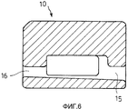
фиг.6 - разрез по линии VI-VI на фиг.3.6 is a section along the line VI-VI in figure 3.
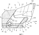
На чертежах поз.10 обозначен состоящий из литой детали резцедержатель, выполненный в виде держателя для вставленного в него вспарывающего резца 1. Вспарывающий резец 1 содержит расположенную в монтажном положении вне резцедержателя 10 головку 2 с впаянной твердосплавной режущей пластиной 3А и, по меньшей мере, одним впаянным твердосплавным штифтом 3В на режущих поверхностях. За одно целое с головкой 2 соединен хвостовик 5, который вставлен в открытый (на фиг.1) на верхней стороне 11 резцедержателя 10 монтажный карман 12 и размещен в кармане 12 с геометрическим замыканием. Хвостовик 5 имеет две стороны большой площади, из которых изображенная на фиг.1 сторона 6 снабжена ориентированной приблизительно параллельно нижней стороне 7 хвостовика канавкой 8 для ввода стержня 51 обозначенного поз.50 фиксирующего болта, посредством которой фиксируют монтажное положение резца 1 в монтажном кармане 12 резцедержателя 10.In the drawings, pos. 10, a tool holder consisting of a molded part is made in the form of a holder for the tapping tool 1. The tapping tool 1 comprises a
Изображенный резцедержатель 10 предназначен, в частности, для приваривания к поворотному резценосителю (не показан) подземного, ведомого по направляющей цепного скребкового транспортера добычного струга в качестве самого нижнего или одного из двух самых нижних резцедержателей. Для этого резцедержатель 10 приваривают его нижней стороной 26 к резценосителю таким образом, что монтажный карман 12 или верхняя сторона 11 резцедержателя 10 обращена к лежачему боку выемочного забоя, с тем чтобы режущая пластина 3А и режущий штифт 3В резца 1 могли отделять уголь на переходе от лежачего бока к очистному забою. При работе струг (не показан) движется в направлении стрелки А на фиг.1. Стрелка А указывает, следовательно, рабочее направление струга для вспарывающего резца 1, и в монтажном положении на резценосителе резцедержатель 10 ориентирован таким образом, что продольная средняя плоскость монтажного кармана 12 резцедержателя 10, как показано на фиг.1, параллельна рабочему направлению А струга. При работе видимая по отношению к фиг.1 и рабочему направлению А струга сторона 6 хвостовика 5 резца указывает в направлении очистного забоя, тогда как противоположная сторона хвостовика указывает в направлении закладочной стороны, а хвостовик 5 поддерживается на своей передней стороне 4 передней опорной стенкой 13 кармана для резца, а на своей нерабочей стороне 9 - задней опорной стенкой 14 в монтажном кармане 12 резцедержателя 10. Передняя сторона 4 хвостовика 5 проходит по всей его высоте прямолинейно, однако относительно рабочего направления А струга наклонена назад к нижней стороне 7 хвостовика, тогда как нерабочая сторона 9 на большей части высоты хвостовика проходит параллельно передней стороне 4, но вблизи нижней стороны переходит в загнутый под прямым углом к рабочему направлению А струга участок 9А. Внутренние поверхности монтажного кармана 12 на передней 13 и задней 14 опорных стенках проходят соответственно с наклоном к рабочему направлению струга, причем угол наклона составляет около 54,5°.The illustrated
На фиг.1 хорошо видно также, что стержень 51 фиксирующего болта 50 проходит как через отверстие 15 для ввода в передней опорной стенке 13, так и через монтажное отверстие 16 в задней опорной стенке 14 резцедержателя 10 или входит в них и одновременно лежит частично в канавке 8 для ввода в стенке 6 хвостовика 5 резца. Для фиксации фиксирующего болта 50 в монтажном положении, в котором его головка 52 прилегает к внешней стороне 17 передней опорной стенки 13, в углублении 8А в стороне 6 хвостовика расположена L-образная пластмассовая зажимная деталь 60, короткое запорное плечо 61 которой снабжено отверстием или круглой выемкой и входит в желобок 53 для ввода на фиксирующем болте 50. Для удаления фиксирующего болта 50 из монтажного положения к его головке 52 следует приложить, следовательно, сравнительно большое усилие в направлении А стрелки, т.е. в рабочем направлении струга, причем для приложения этого усилия необходим инструмент, поскольку при работе струга действующие на резец 1 усилия направлены навстречу рабочему направлению А струга. Описанная выше принципиальная конструкция резцедержателя 10 с вставленным и фиксированным в его монтажном кармане 12 хвостовиком 5 резца 1 известна специалисту.Figure 1 also clearly shows that the
Согласно изобретению, как это показано на фиг.1 лишь схематично, одна из двух боковых опорных стенок, а именно боковая опорная стенка 20, расположенная при работе струга со стороны закладки и поэтому на фиг.1 за резцом 1, выполнена длиннее и выше, чем другая опорная стенка, расположенная со стороны очистного забоя (не показана). Более длинная опорная стенка 20 одновременно возвышается над передней опорной стенкой 13. Это видно из нижеследующего описания резцедержателя 10, подробно изображенного на фиг.2-6.According to the invention, as shown in FIG. 1 only schematically, one of the two side support walls, namely the
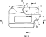
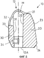
На фиг.2 видно, что монтажный карман 12 резцедержателя 10 ограничен передней 13, задней 14 и двумя боковыми 20, 21 опорными стенками. В частности, в сочетании с фиг.3 и 5 при этом видно, что верхняя сторона 21, расположенная при работе со стороны закладки, опорной стенки 20 возвышается над верхней стороной 32 другой опорной стенки 30, расположенной со стороны очистного забоя, примерно на 1/3 всей длины более короткой опорной стенки 30 по всей длине монтажного кармана 12 с одинаковым размером по высоте. Ограничивающая монтажный карман 12 внутренняя поверхность 22 опорной стенки 20 образует поэтому для хвостовика резца по высоте монтажного кармана 12 подпорку с гораздо большей площадью, чем внутренняя поверхность 31 более короткой опорной стенки 30. Поскольку струг при работе, т.е. когда он движется в рабочем направлении (А, фиг.1), должен быть подвинут для добычи угля на нужную глубину резания к очистному забою, вставленный в резцедержатель 10 хвостовик резца и опорная стенка 20 нагружены со стороны закладки сильнее, чем со стороны очистного забоя. Более длинная опорная внутренняя поверхность 22 боковой опорной стенки 20 и выбранная гораздо большей толщина последней приспособлены к этим нагрузкам, причем рассматриваемая по высоте более длинная опорная поверхность опорной стенки 20 дает то особое преимущество, что оказываемый через головку резца на его хвостовик опрокидывающий момент воспринимается со стороны закладки почти по всей высоте хвостовика резца. Весь участок более длинной боковой опорной стенки 20, возвышающийся над верхней стороной 18 передней опорной стенки 13 и верхней стороной 32 более короткой боковой опорной стенки 30, образует, следовательно, дополнительное, расположенное со стороны закладки опорное плечо для стороны хвостовика резца, расположенной со стороны закладки.Figure 2 shows that the mounting
Более длинная опорная стенка 20 проходит до выступающего носика 19 передней опорной стенки 13. В частности, фиг.5 иллюстрирует при этом, что поверхность 21 более длинной опорной стенки 20 и поверхность 32 более короткой боковой опорной стенки 30 проходят наклонно к монтажному карману 12, причем обе поверхности 21, 32 предпочтительно образуют с продольной средней плоскостью М монтажного кармана 12 соответственно угол около 93°. В то же время обе внутренние поверхности 31,22 боковых опорных стенок 30,20 расходятся под небольшим углом около 1,8° относительно продольной средней плоскости М, за счет чего монтажный карман 12 равномерно расширяется в обе стороны от открытого дна 12А к поверхностям 21, 32.The
Из фиг.3-5 далее видно, что задняя опорная стенка 14 имеет в средней области возвышение 40, которое еще незначительно выступает не только за более короткую боковую опорную стенку 30, но и за более длинную и толстую боковую опорную стенку 20, образуя дополнительную со стороны головки подпорку для резца на задней стороне монтажного кармана 12. Переход возвышения 40 к более короткой боковой опорной стенке 30 происходит посредством дугообразного скругленного переходного участка 41 вплоть до поверхности 32 более короткой боковой опорной стенки 30. Включающая в себя переходный участок 41 боковая поверхность задней опорной стенки 14, которая проходит сбоку от монтажного кармана 12 и над более короткой боковой опорной стенкой 30, снабжена нисходящим к карману 12 скругленным желобчатым углублением 42 в качестве вводного вспомогательного приспособления для хвостовика резца.From Figs. 3-5 it can further be seen that the
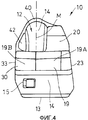
В частности, фиг.4 и 5 показывают, что внешняя стенка 23 более длинной боковой опорной стенки 20 над выполненной вблизи нижней стороны 13 монтажного кармана 12 фаской 24 для приваривания проходит наискось к асимметрично лежащей продольной средней плоскости М монтажного кармана 12, так что толщина боковой опорной стенки 20 дополнительно уменьшается по мере увеличения высоты резцедержателя 10. Фиг.4 показывает также, что выступающий на передней опорной стенке 14 носик 19 снабжен V-образно скошенным желобком, причем обе отдельные поверхности 19А, 19В сходятся под тупым углом приблизительно 175-188°. В то время как выступающий носик 19 обеспечивает защиту головки 52 болта (фиг.1), V-образный скос образует дополнительную опорную поверхность для опорного язычка резца под его головкой (2, фиг.1). Для достижения предпочтительной блокировки фиксирующего болта (50, фиг.1) в резцедержателе 10 высота в свету отверстия 15 для ввода и монтажное отверстие 16 в резцедержателе 10 остается, по существу, постоянной, тогда как их ширина в свету, т.е. протяженность между опорными стенками 20, 30, непрерывно уменьшается к монтажному отверстию 16, как это показано, в частности, на фиг.6.In particular, FIGS. 4 and 5 show that the
Из предшествующего описания специалисту понятно, что изображенный на фиг.1 резец 1 содержит хвостовик 5, задняя, невидимая на фиг.1, сторона которого имеет существенно более длинную, по существу, плоскую контактную поверхность для прилегания к более длинной боковой опорной стенке 20, чем видимая на фиг.1 передняя сторона 5 хвостовика. За счет этого резец согласно изобретению согласован с резцедержателем. У резца согласно изобретению сами стороны хвостовика не обязательно должны быть выполнены плоскими по всей их поверхности, а могут иметь рядом с канавкой для ввода фиксирующего болта также другие углубления. В равной мере, в целом, в качестве контактной поверхности прилегания к ограничительным поверхностям монтажного кармана возникает соответственно плоская контактная зона.From the foregoing description, one skilled in the art will recognize that the cutter 1 shown in FIG. 1 comprises a shank 5, a rear, invisible in FIG. 1, side of which has a substantially longer, substantially flat contact surface for adhering to a longer
Claims (21)
Applications Claiming Priority (2)
| Application Number | Priority Date | Filing Date | Title |
|---|---|---|---|
| DE20320161U DE20320161U1 (en) | 2003-12-29 | 2003-12-29 | Chisel holder for a planer chisel of a coal or mining plane and planer chisel |
| DE20320161.2 | 2003-12-29 |
Publications (2)
| Publication Number | Publication Date |
|---|---|
| RU2004138731A RU2004138731A (en) | 2006-06-10 |
| RU2334103C2 true RU2334103C2 (en) | 2008-09-20 |
Family
ID=31984922
Family Applications (1)
| Application Number | Title | Priority Date | Filing Date |
|---|---|---|---|
| RU2004138731/03A RU2334103C2 (en) | 2003-12-29 | 2004-12-28 | Toolhead for carbon or winning drawknife cutter, and cutter |
Country Status (5)
| Country | Link |
|---|---|
| US (1) | US7073870B2 (en) |
| CN (1) | CN100564799C (en) |
| DE (1) | DE20320161U1 (en) |
| PL (1) | PL206240B1 (en) |
| RU (1) | RU2334103C2 (en) |
Cited By (1)
| Publication number | Priority date | Publication date | Assignee | Title |
|---|---|---|---|---|
| RU2745564C2 (en) * | 2016-06-03 | 2021-03-29 | ДЖОЙ ГЛОБАЛ АНДЕРГРАУНД МАЙНИНГ ЭлЭлСи | Tooth with tapered surface reduced grip |
Families Citing this family (14)
| Publication number | Priority date | Publication date | Assignee | Title |
|---|---|---|---|---|
| DE20320163U1 (en) * | 2003-12-29 | 2004-03-04 | Dbt Gmbh | Chisel holder for a planer chisel |
| DE102005036359A1 (en) * | 2005-07-29 | 2007-02-01 | Dbt Gmbh | Method for recovering coal comprises using a coal planing device having a coal plane which moves to and fro between a drive station and a reversing station with a reversing chain wheel |
| CA2759353C (en) | 2010-11-30 | 2019-06-11 | Harnischfeger Technologies, Inc. | Pick holder |
| CN102400687A (en) * | 2011-11-22 | 2012-04-04 | 无锡速力特机械科技有限公司 | Special wedge-type section tooth structure for shearer drum |
| CN102425414A (en) * | 2011-11-22 | 2012-04-25 | 无锡速力特机械科技有限公司 | Special grooved pick structure for coal mining machine roller |
| USD709112S1 (en) | 2011-11-30 | 2014-07-15 | Harnischfeger Technologies, Inc. | Pick holder |
| USD720375S1 (en) | 2011-11-30 | 2014-12-30 | Harnischfeger Technologies, Inc. | Pick holder |
| CN102979522B (en) * | 2012-12-13 | 2015-01-14 | 三一重型装备有限公司 | Planer cutter and coal planer |
| CN103277097B (en) * | 2013-05-17 | 2015-04-15 | 中煤张家口煤矿机械有限责任公司 | Rotary tool apron structure capable of being quickly disassembled and assembled of coal plough |
| GB2543220A (en) | 2013-06-18 | 2017-04-12 | Esco Corp | Mineral winning pick, pick holder, and combination |
| EP2952676A1 (en) * | 2014-06-03 | 2015-12-09 | Caterpillar Global Mining Europe GmbH | Plow bit assembly |
| DE102014112539A1 (en) | 2014-09-01 | 2016-03-03 | Wirtgen Gmbh | Wear protective cap |
| AU2015210467B2 (en) * | 2014-09-11 | 2019-08-08 | Kennametal Inc. | Cutting tool mounting assembly |
| CN106677784A (en) * | 2017-03-03 | 2017-05-17 | 胡沿东 | Roller for mining mechanical equipment |
Citations (8)
| Publication number | Priority date | Publication date | Assignee | Title |
|---|---|---|---|---|
| DE3209410A1 (en) * | 1981-06-06 | 1982-12-23 | Gewerkschaft Eisenhütte Westfalia, 4670 Lünen | CHISEL ARRANGEMENT, ESPECIALLY FOR CARBON AND THE LIKE |
| US4557525A (en) * | 1982-03-16 | 1985-12-10 | Gewerkschaft Eisenhutte Westfalia | Cutter bit assembly |
| SU1231222A1 (en) * | 1982-12-23 | 1986-05-15 | Шахтинский научно-исследовательский и проектно-конструкторский угольный институт им.А.М.Терпигорева | Working member for mining machine |
| SU1375144A3 (en) * | 1984-02-08 | 1988-02-15 | Геверкшафт Эйзенхютте Вестфалия (Фирма) | Arrangement for securing cutter, in particular for coal plough |
| US4915455A (en) * | 1988-11-09 | 1990-04-10 | Joy Technologies Inc. | Miner cutting bit holding apparatus |
| US5011229A (en) * | 1988-11-09 | 1991-04-30 | Joy Technologies Inc. | Miner cutting bit holding apparatus |
| DE29803944U1 (en) * | 1998-03-06 | 1998-04-30 | DBT Deutsche Bergbau-Technik GmbH, 44534 Lünen | Chisel lock for a planer chisel |
| DE29901985U1 (en) * | 1999-02-05 | 1999-04-08 | DBT Deutsche Bergbau-Technik GmbH, 44534 Lünen | Chisel holder for a planer chisel |
Family Cites Families (4)
| Publication number | Priority date | Publication date | Assignee | Title |
|---|---|---|---|---|
| DE3638135A1 (en) * | 1986-11-08 | 1988-05-11 | Gewerk Eisenhuette Westfalia | GROUND CHISEL FOR MINING PLANE |
| DE3900140C1 (en) * | 1989-01-04 | 1990-08-16 | Halbach & Braun Industrieanlagen, 5600 Wuppertal, De | |
| DE4300534C2 (en) * | 1993-01-12 | 2001-10-04 | Dbt Gmbh | Extraction planer for underground extraction |
| DE4328863C2 (en) * | 1993-08-27 | 2001-09-27 | Dbt Gmbh | Mining facility for underground mining |
-
2003
- 2003-12-29 DE DE20320161U patent/DE20320161U1/en not_active Expired - Lifetime
-
2004
- 2004-11-24 CN CNB2004100950405A patent/CN100564799C/en not_active Expired - Lifetime
- 2004-11-30 US US11/000,024 patent/US7073870B2/en not_active Expired - Lifetime
- 2004-12-20 PL PL371844A patent/PL206240B1/en unknown
- 2004-12-28 RU RU2004138731/03A patent/RU2334103C2/en active
Patent Citations (8)
| Publication number | Priority date | Publication date | Assignee | Title |
|---|---|---|---|---|
| DE3209410A1 (en) * | 1981-06-06 | 1982-12-23 | Gewerkschaft Eisenhütte Westfalia, 4670 Lünen | CHISEL ARRANGEMENT, ESPECIALLY FOR CARBON AND THE LIKE |
| US4557525A (en) * | 1982-03-16 | 1985-12-10 | Gewerkschaft Eisenhutte Westfalia | Cutter bit assembly |
| SU1231222A1 (en) * | 1982-12-23 | 1986-05-15 | Шахтинский научно-исследовательский и проектно-конструкторский угольный институт им.А.М.Терпигорева | Working member for mining machine |
| SU1375144A3 (en) * | 1984-02-08 | 1988-02-15 | Геверкшафт Эйзенхютте Вестфалия (Фирма) | Arrangement for securing cutter, in particular for coal plough |
| US4915455A (en) * | 1988-11-09 | 1990-04-10 | Joy Technologies Inc. | Miner cutting bit holding apparatus |
| US5011229A (en) * | 1988-11-09 | 1991-04-30 | Joy Technologies Inc. | Miner cutting bit holding apparatus |
| DE29803944U1 (en) * | 1998-03-06 | 1998-04-30 | DBT Deutsche Bergbau-Technik GmbH, 44534 Lünen | Chisel lock for a planer chisel |
| DE29901985U1 (en) * | 1999-02-05 | 1999-04-08 | DBT Deutsche Bergbau-Technik GmbH, 44534 Lünen | Chisel holder for a planer chisel |
Cited By (1)
| Publication number | Priority date | Publication date | Assignee | Title |
|---|---|---|---|---|
| RU2745564C2 (en) * | 2016-06-03 | 2021-03-29 | ДЖОЙ ГЛОБАЛ АНДЕРГРАУНД МАЙНИНГ ЭлЭлСи | Tooth with tapered surface reduced grip |
Also Published As
| Publication number | Publication date |
|---|---|
| US7073870B2 (en) | 2006-07-11 |
| CN100564799C (en) | 2009-12-02 |
| DE20320161U1 (en) | 2004-03-04 |
| PL371844A1 (en) | 2005-07-11 |
| RU2004138731A (en) | 2006-06-10 |
| US20050140099A1 (en) | 2005-06-30 |
| CN1637231A (en) | 2005-07-13 |
| PL206240B1 (en) | 2010-07-30 |
Similar Documents
| Publication | Publication Date | Title |
|---|---|---|
| RU2334103C2 (en) | Toolhead for carbon or winning drawknife cutter, and cutter | |
| JP3626190B2 (en) | Thread cutting insert | |
| US3342532A (en) | Cutting tool comprising holder freely rotatable in socket with bit frictionally attached | |
| US4969779A (en) | Cutting insert | |
| EP2838682B1 (en) | Cutting insert chip-control arrangement | |
| US20090146490A1 (en) | Breaking or excavating tool with cemented tungsten carbide insert and ring | |
| CN100436075C (en) | A chisel | |
| CN102947029A (en) | Cutting tool | |
| JPH08168902A (en) | Insert for cutting | |
| US7393061B2 (en) | Coal plow cutter | |
| DK1175531T3 (en) | Ice scraper with non-rotatable tools with shielded cutting inserts | |
| RU2334104C2 (en) | Toolhead for drawknife cutter | |
| RU2071562C1 (en) | Cutter for mining machinery | |
| JPH11223082A (en) | Excavating tooth for excavator | |
| KR100304414B1 (en) | Hole-chamfering cut tool | |
| US2950096A (en) | Cutting bits and bit holders | |
| GB2069031A (en) | Floor cutter bit | |
| RU237950U1 (en) | Rock-cutting tool | |
| US7347501B2 (en) | Plow baseplate | |
| CN106414897A (en) | Plow bit assembly | |
| US3343879A (en) | Long wall mining planer having mine floor related guiding means | |
| RU2018658C1 (en) | Cutter for coal mining machine | |
| US2873960A (en) | Coal cutting bit having three cutting tips | |
| AU650602B2 (en) | Carbide tip and pick | |
| RU2307932C1 (en) | Rock-cutting tool |
Legal Events
| Date | Code | Title | Description |
|---|---|---|---|
| PD4A | Correction of name of patent owner |