RU2333373C2 - Rotor-piston engine housing - Google Patents
Rotor-piston engine housing Download PDFInfo
- Publication number
- RU2333373C2 RU2333373C2 RU2005114107/06A RU2005114107A RU2333373C2 RU 2333373 C2 RU2333373 C2 RU 2333373C2 RU 2005114107/06 A RU2005114107/06 A RU 2005114107/06A RU 2005114107 A RU2005114107 A RU 2005114107A RU 2333373 C2 RU2333373 C2 RU 2333373C2
- Authority
- RU
- Russia
- Prior art keywords
- stator
- channels
- hot zone
- rotor
- bolts
- Prior art date
Links
- 230000008878 coupling Effects 0.000 claims abstract description 15
- 238000010168 coupling process Methods 0.000 claims abstract description 15
- 238000005859 coupling reaction Methods 0.000 claims abstract description 15
- 238000010438 heat treatment Methods 0.000 claims abstract description 3
- 239000002826 coolant Substances 0.000 claims description 16
- 238000001816 cooling Methods 0.000 claims description 10
- 239000000203 mixture Substances 0.000 claims description 5
- 239000012809 cooling fluid Substances 0.000 claims description 2
- 238000005452 bending Methods 0.000 abstract description 5
- 239000000110 cooling liquid Substances 0.000 abstract description 5
- 230000000694 effects Effects 0.000 abstract description 5
- 238000002485 combustion reaction Methods 0.000 abstract description 3
- 230000003247 decreasing effect Effects 0.000 abstract 1
- 239000000126 substance Substances 0.000 abstract 1
- 239000000446 fuel Substances 0.000 description 4
- 230000007423 decrease Effects 0.000 description 3
- XLYOFNOQVPJJNP-UHFFFAOYSA-N water Substances O XLYOFNOQVPJJNP-UHFFFAOYSA-N 0.000 description 2
- 230000009471 action Effects 0.000 description 1
- 230000008859 change Effects 0.000 description 1
- 230000006866 deterioration Effects 0.000 description 1
- 239000007788 liquid Substances 0.000 description 1
- 239000000463 material Substances 0.000 description 1
- 238000000034 method Methods 0.000 description 1
- 230000002093 peripheral effect Effects 0.000 description 1
- 230000009467 reduction Effects 0.000 description 1
- 230000001988 toxicity Effects 0.000 description 1
- 231100000419 toxicity Toxicity 0.000 description 1
Images
Landscapes
- Fuel-Injection Apparatus (AREA)
- Motor Or Generator Cooling System (AREA)
Abstract
Description
Изобретение относится к двигателестроению, в частности к роторно-поршневым двигателям внутреннего сгорания (далее РПД).The invention relates to engine building, in particular to rotary piston internal combustion engines (hereinafter RPD).
Известна система охлаждения РПД (а.с. СССР №358534, Мкл. F02B 55/10), где с целью выравнивания поля температур по деталям корпуса РПД и уменьшения деформации статора жидкостное охлаждение горячей и холодной зон корпуса РПД осуществляется по двум независимым каналам системы охлаждения.A known RPD cooling system (USSR AS No. 358534, Ml. F02B 55/10), where, in order to equalize the temperature field on the parts of the RPD housing and reduce the stator deformation, liquid cooling of the hot and cold zones of the RPD housing is carried out through two independent channels of the cooling system .
Недостатками этого изобретения являются ограниченные возможности по выравниванию температурного поля статора на максимально возможном для используемых в этих деталях материалах температурном уровне.The disadvantages of this invention are the limited possibilities for leveling the temperature field of the stator at the maximum possible temperature level for the materials used in these parts.
Холодную зону статора нельзя нагреть выше температуры циркулирующей там охлаждающей жидкости. Чтобы выравнить температурное поле в холодной и горячей зонах, нужно значительно захолодить горячую зону статора, что приведет к ухудшению процессов горения, увеличению расхода топлива, дополнительным механическим потерям на привод водяного насоса, увеличению габаритов и веса силовой установки.The cold zone of the stator cannot be heated above the temperature of the coolant circulating there. In order to equalize the temperature field in cold and hot zones, it is necessary to cool the hot zone of the stator significantly, which will lead to a deterioration in combustion processes, an increase in fuel consumption, additional mechanical losses on the drive of the water pump, an increase in the dimensions and weight of the power plant.
Известна система охлаждения РПД (патент США 3964445 от 22.06.1976 г, прототип предполагаемого изобретения), где с целью выравнивания поля температур по статору и крышкам статора, уменьшения деформации статора и крышек статора охлаждающую жидкость направляют в горячую зону статора и крышек статора, а скорость потока охлаждающей жидкости формируют проходными сечениями каналов и дефлекторами.A known RPD cooling system (US patent 3964445 dated 06/22/1976, prototype of the alleged invention), where in order to equalize the temperature field along the stator and stator covers, to reduce the deformation of the stator and stator covers, the coolant is directed to the hot zone of the stator and stator covers, and the speed coolant flow is formed by passage sections of channels and deflectors.
Недостатками этого изобретения, с точки зрения решения задачи уменьшения деформации статора и крышек статора, являются отсутствие мероприятий, позволяющих уменьшить силовое воздействие на внутреннюю стенку-обечайку, что приводит к ее деформации, деформации крышек статора, нарушениям герметичности по масляным уплотнениям ротора, повышенному расходу масла, повышенному износу радиальных и торцовых уплотнений ротора, как следствие, - снижению ресурса РПД. Так, поле температур в прототипе не выравнивается по ширине статора, а стяжка болтами (шпильками) корпуса РПД осуществляется по варианту, создающему максимальный изгибающий момент, ведущий к деформациям статора и крышек статора. Одной из главных причин этого является то, что в охлаждении высокотемпературных зон статора и крышек статора участвует поток охлаждающей жидкости, параметры которой невозможно менять в широких пределах.The disadvantages of this invention, from the point of view of solving the problem of reducing the deformation of the stator and stator covers, are the lack of measures to reduce the force effect on the inner wall of the shell, which leads to its deformation, deformation of the stator covers, leakage in the rotor oil seals, increased oil consumption , increased wear of the radial and mechanical seals of the rotor, as a result, a decrease in the resource RPD. So, the temperature field in the prototype is not aligned across the width of the stator, and the coupler with bolts (pins) of the RPD housing is carried out according to the option that creates the maximum bending moment leading to deformations of the stator and stator covers. One of the main reasons for this is that a coolant flow is involved in the cooling of the high-temperature zones of the stator and stator covers, the parameters of which cannot be changed over a wide range.
Технический результат изобретения заключается в уменьшении действия изгибающего момента, деформирующего внутреннюю стенку-обечайку статора и крышки статора.The technical result of the invention is to reduce the effect of bending moment, deforming the inner wall-shell of the stator and stator cover.
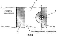
Указанный технический результат при осуществлении изобретения достигается тем, что в известном корпусе РПД, по крайней мере односекционного, содержащем статор, ротор, эксцентриковый вал, крышки статора, соединенные с помощью болтов или шпилек, соединительные болты или шпильки проходят через отверстия во внутреннем контуре статора и максимально приближены к внутренней рабочей поверхности статора, при этом в горячей зоне, имеющей нагрев внутренней стенки-обечайки до температуры 240-260°С, расстояние от центра стяжных болтов или шпилек до внутренней рабочей поверхности внутренней стенки-обечайки статора находится в пределах S=1,2...1,5d, где d - диаметр стяжного болта или шпильки. Охлаждение статора осуществляется охлаждающей жидкостью, движущейся по узким щелевым каналам, образованным отверстиями в статоре и стяжными болтами или шпильками, при этом ширина щели составляет величину h=0,1...0,2d. В горячей зоне, в местах расположения свечей зажигания, соединительные болты или шпильки со щелевыми каналами вокруг них расположены во внутреннем контуре статора близко друг от друга. Каналы подвода охлаждающей жидкости расположены в средней части статора - горячей зоне. Каналы подвода охлаждающей жидкости к крышкам статора выполнены в виде продолжения каналов охлаждения статора. В статоре имеются каналы для подвода на впуск РПД воздуха или топливно-воздушной смеси, которые проходят через горячие зоны статора.The specified technical result in the implementation of the invention is achieved by the fact that in the known housing RPD, at least one-section, containing a stator, rotor, eccentric shaft, stator covers connected by bolts or studs, connecting bolts or studs pass through holes in the inner circuit of the stator and as close as possible to the inner working surface of the stator, while in the hot zone having heating of the inner shell wall to a temperature of 240-260 ° C, the distance from the center of the coupling bolts or studs to the morning working surface of the inner wall-shell of the stator is within S = 1.2 ... 1.5d, where d is the diameter of the coupling bolt or stud. The stator is cooled by a cooling fluid moving along narrow slotted channels formed by openings in the stator and coupling bolts or studs, while the slot width is h = 0.1 ... 0.2d. In the hot zone, at the locations of the spark plugs, connecting bolts or studs with slotted channels around them are located in the inner circuit of the stator close to each other. Coolant supply channels are located in the middle part of the stator - the hot zone. The channels for supplying coolant to the stator covers are made as a continuation of the stator cooling channels. The stator has channels for supplying air or fuel-air mixture to the inlet of the RPD, which pass through the hot zones of the stator.
Сравнение научно-технической и патентной документации на дату приоритета в основной и смежной рубриках МКИ показывает, что совокупность существенных признаков заявленного решения ранее не была известна, следовательно, оно соответствует условию патентоспособности "новизна".Comparison of scientific, technical and patent documentation on the priority date in the main and related sections of the MKI shows that the set of essential features of the claimed solution was not previously known, therefore, it meets the patentability condition of “novelty”.
Анализ известных технических решений в данной области техники показал, что предложенное устройство имеет признаки, которые отсутствуют в известных технических решениях, а использование их в заявленной совокупности признаков дает возможность получить новый технический результат, следовательно, предложенное техническое решение имеет изобретательский уровень по сравнению с существующим уровнем техники.The analysis of known technical solutions in the art showed that the proposed device has features that are not available in the known technical solutions, and their use in the claimed combination of features makes it possible to obtain a new technical result, therefore, the proposed technical solution has an inventive step compared to the existing level technicians.
Предложенное техническое решение промышленно применимо, т.к. может быть изготовлено промышленным способом, работоспособно, осуществимо и воспроизводимо, следовательно, соответствует условию патентоспособности "промышленная применимость".The proposed technical solution is industrially applicable, because can be manufactured industrially, efficiently, feasibly and reproducibly, therefore, meets the patentability condition "industrial applicability".
Изобретение поясняется чертежами и проставленными на них позициями.The invention is illustrated by drawings and affixed to them positions.
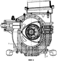
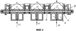
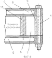
РПД, по крайней мере односекционный, содержит статор 1 (фиг.1), ротор 2, вал эксцентриковый 3, болты или шпильки соединения корпусных деталей 4, каналы 5 впуска воздуха или топливно-воздушной смеси, крышки 6 статора (фиг.3, 4), каналы 7 охлаждения статора (фиг.2, 3, 4, 5, 6, 7), каналы 8 охлаждения крышек статора (фиг.3).RPD, at least one-section, contains a stator 1 (Fig. 1), a rotor 2, an eccentric shaft 3, bolts or studs for connecting
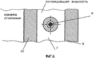
Фиг.5 и 6 являются поясняющими, в частности, на фиг.5 корпус двигателя стягивается с помощью болтов или шпилек, расположенных в отверстиях, проходящих по внешней стенке-обечайке 9, как это использовано в РПД ф.Ванкель, а также в РПД ВАЗ 415, ВАЗ 416 (ОАО "АВТОВАЗ", г. Тольятти), а на фиг.6 - аналогично, в средней части статоров между внешней и внутренней стенкой-обечайкой 10, что имеет место в конструкциях РПД ф.Мазда, а также РПД ВАЗ 311, ВАЗ 413.FIGS. 5 and 6 are explanatory, in particular, in FIG. 5, the engine housing is pulled together with bolts or studs located in holes passing along the outer wall of the
При работе РПД внутренняя стенка-обечайка может нагреваться в зонах II и III фиг.1 до температуры 240-260°С, в то время как температура внутренней стенки-обечайки в зоне I и температура внешней стенки-обечайки соизмеримы с температурой охлаждающей жидкости 90-120°С.During the operation of the RPD, the inner shell wall can be heated in zones II and III of FIG. 1 to a temperature of 240-260 ° C, while the temperature of the inner shell wall in zone I and the temperature of the outer shell wall are comparable with a coolant temperature of 90- 120 ° C.
Увеличение ширины статора по внутренней стенке-обечайке в большей мере, чем увеличение ширины статора по внешней стенке-обечайке приводит к перераспределению силовых нагрузок в корпусе РПД таким образом, что увеличившаяся нагрузка на внутреннюю стенку-обечайку приводит к ее деформации, а возникающий изгибающий момент приводит к деформации крышек статора, нарушению герметичности по масляным уплотнениям ротора, повышенному расходу масла, повышенной подвижности радиальных и торцовых уплотнений ротора, их износу и снижению ресурса РПД. Назовем это фактором 1.An increase in the stator width along the inner wall of the shell to a greater extent than an increase in the width of the stator along the outer wall of the shell leads to a redistribution of power loads in the housing of the RPD so that the increased load on the inner wall of the shell leads to its deformation, and the resulting bending moment leads to to deformation of the stator covers, violation of the tightness of the oil seals of the rotor, increased oil consumption, increased mobility of the radial and mechanical seals of the rotor, their wear and reduction in the life of the RPD. We call this factor 1.
Известно, что в РПД отдельные фазы рабочего процесса осуществляются в определенных участках корпуса РПД.It is known that in RPD, individual phases of the workflow are carried out in certain parts of the RPD enclosure.
Экспериментально установлено, что в РПД по внутреннему контуру статора от окон впуска топливно-воздушной смеси до окон выпуска отработанных газов температура внутренней стенки-обечайки статора может меняться в пределах от 80°С в зоне I фиг.1 до 260°С в зоне II. Это обстоятельство, назовем его фактором 2, приводит к термическим деформациям деталей корпуса РПД, изменениям изначально заданных геометрических размеров статора и крышек статора, повышенной подвижности элементов уплотнения ротора, их чрезмерному износу, снижению ресурса РПД.It was experimentally established that in the RPD along the inner stator contour from the fuel-air mixture inlet windows to the exhaust gas exhaust windows, the temperature of the inner wall of the stator shell can vary from 80 ° C in zone I of Fig. 1 to 260 ° C in zone II. This circumstance, let us call it factor 2, leads to thermal deformations of the RPD housing parts, changes in the initial geometrical dimensions of the stator and stator covers, increased mobility of the rotor seal elements, their excessive wear, and reduced RPD resource.
Кроме того, установлено, что существует неравномерное поле температур и по ширине статора, назовем это фактором 3.In addition, it was found that there is an uneven temperature field and across the width of the stator, we call this factor 3.
В средней по ширине зоне статора, особенно в местах расположения свечей зажигания, температура внутренних стенок-обечаек статора может достигать 360÷370°С, в то время как температура стенок-обечаек статора в местах контакта с крышками статора 180÷190°С.In the stator’s middle-wide zone, especially at the locations of the spark plugs, the temperature of the inner walls of the stator shells can reach 360–370 ° С, while the temperature of the walls of the shells of the stator in contact with the stator covers is 180–190 ° С.
Это обстоятельство приводит к деформациям внутренних стенок-обечаек статора по ширине, прорыву газов в зазорах между поверхностью статора и радиальными уплотнениями роторов - лопатками, падению мощности РПД и повышенному расходу топлива.This circumstance leads to deformation of the inner walls of the stator shells in width, gas breakthrough in the gaps between the stator surface and the rotor radial seals - blades, a drop in RPD power and increased fuel consumption.
В предлагаемом РПД в отличие от прототипа с целью уменьшения действия изгибающего момента, деформирующего внутреннюю стенку-обечайку статора и крышки статора, болты стяжные, расположенные в горячей зоне статора, максимально приближены к рабочей поверхности статора.In the proposed RPD, in contrast to the prototype, in order to reduce the effect of bending moment, deforming the inner wall-shell of the stator and stator cover, the coupling bolts located in the hot zone of the stator are as close as possible to the working surface of the stator.
Экспериментально установлено, что расстояние от центра стяжных болтов в горячей зоне II Фиг.1 до внутренней рабочей поверхности внутренней стенки-обечайки статора должно находиться в следующих пределах:It was experimentally established that the distance from the center of the coupling bolts in the hot zone II of Figure 1 to the inner working surface of the inner wall of the stator shell should be within the following limits:
S=1,2÷1,5d, гдеS = 1.2 ÷ 1.5d, where
S - расстояние от внутренней рабочей поверхности статора до центра стяжных болтов,S is the distance from the inner working surface of the stator to the center of the coupling bolts,
d - диаметр болта стяжного.d is the diameter of the coupling bolt.
Второе отличие от прототипа предлагаемой системы охлаждения заключается в том, что движение охлаждающей жидкости происходит по узким щелевым каналам 7, образованным отверстиями 12 в статоре, крышках статора и стяжными болтами 4, с высокими скоростями, чем обеспечивается интенсификация передачи тепла от стенок каналов статора в охлаждающую жидкость.The second difference from the prototype of the proposed cooling system is that the movement of the coolant occurs through narrow
Экспериментально установлено, что величина щелевого канала 7 должна находиться в следующих пределах:It was experimentally established that the size of the
h=0,1÷0,2d, гдеh = 0.1 ÷ 0.2d, where
h - величина щелевого канала,h is the size of the slotted channel,
d - диаметр болта стяжного.d is the diameter of the coupling bolt.
Третье отличие от прототипа заключается в том, что с целью уменьшения деформации статора и крышек статора от действий термических нагрузок, возникающих от неравномерного поля температур по всему внутреннему контуру статора, охлаждающая жидкость подается в горячие зоны II и III, фиг.1, статора параллельными каналами, формирующими теплосъем, больший там, где выше температура внутреннего контура статора.The third difference from the prototype is that in order to reduce the deformation of the stator and stator covers from the effects of thermal loads arising from an uneven temperature field along the entire inner contour of the stator, the coolant is supplied to the hot zones II and III, figure 1, of the stator with parallel channels forming heat removal, greater where the temperature of the internal circuit of the stator is higher.
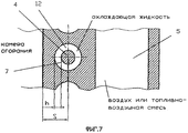
Четвертое отличие от прототипа заключается в том, что охлаждающая жидкость подается в статор каналом 11, фиг 2, 3, в его центральную среднюю часть, как наиболее горячую, и направляется в сторону крышек статора по каналам 7, фиг.2, 3, 7, где поверхность статора менее нагрета. По мере движения охлаждающей жидкости по каналам 7, фиг.3, от средней части статора к его периферийным зонам ее температура повышается, уменьшается теплопередача от рабочей поверхности статора в охлаждающую жидкость, выравнивается поле температур по ширине статора, уменьшается деформация, вызываемая действием фактора 3.The fourth difference from the prototype is that the coolant is supplied to the stator by
Пятое отличие от прототипа заключается в том, что охлаждающая жидкость подается одновременно в каждый из статоров многосекционного РПД по каналам 11, фиг 2, 3, распределяется в каналы 7, фиг 3, 7. Далее охлаждающая жидкость поступает по каналам 8, фиг 3, в крышки статоров, выходит из РПД, проходит термостат, радиатор, поступает в водяной насос и вновь по каналам 11, фиг.2, 3, направляется в РПД.The fifth difference from the prototype is that the coolant is supplied simultaneously to each of the stators of the multi-section RPD through
Шестое отличие от прототипа заключается в том, что статор РПД имеет воздушные каналы 5, фиг 1, 7, проходящие по внешнему контуру статора, через которые воздух или топливно-воздушная смесь (ТВС) подаются в РПД, нагреваются и охлаждают по крайней мере часть горячих зон II и III, фиг.1, статора. При этом статор совмещает в себе две функции: статор как основная деталь корпуса двигателя и статор как часть системы впуска ТВС двигателя, чем обеспечивается их дополнительная жесткость и компактность двигателя.The sixth difference from the prototype is that the RPD stator has
Благодаря изобретению стало возможным свести к минимуму деформации внутренних стенок-обечаек статора по ширине и длине рабочей поверхности, исключить прорыв газов через зазоры между поверхностями статора и радиальными уплотнениями ротора, что в конечном итоге позволило повысить мощность РПД, уменьшить расход топлива и снизить токсичность выхлопных газов.Thanks to the invention, it became possible to minimize the deformation of the inner walls of the stator shells along the width and length of the working surface, to prevent gas breakthrough through the gaps between the stator surfaces and the radial rotor seals, which ultimately made it possible to increase the RPD power, reduce fuel consumption and reduce exhaust toxicity .
Разумеется, изобретение не ограничивается описанным способом его осуществления, показанным на прилагаемых фигурах. Остаются возможными изменения различных элементов либо замена их технически эквивалентными, не выходящими за пределы объема настоящего изобретения.Of course, the invention is not limited to the described method of its implementation, shown in the accompanying figures. It remains possible to change various elements or replace them with technically equivalent, not beyond the scope of the present invention.
Claims (6)
Priority Applications (1)
| Application Number | Priority Date | Filing Date | Title |
|---|---|---|---|
| RU2005114107/06A RU2333373C2 (en) | 2005-05-11 | 2005-05-11 | Rotor-piston engine housing |
Applications Claiming Priority (1)
| Application Number | Priority Date | Filing Date | Title |
|---|---|---|---|
| RU2005114107/06A RU2333373C2 (en) | 2005-05-11 | 2005-05-11 | Rotor-piston engine housing |
Publications (2)
| Publication Number | Publication Date |
|---|---|
| RU2005114107A RU2005114107A (en) | 2006-11-20 |
| RU2333373C2 true RU2333373C2 (en) | 2008-09-10 |
Family
ID=37501689
Family Applications (1)
| Application Number | Title | Priority Date | Filing Date |
|---|---|---|---|
| RU2005114107/06A RU2333373C2 (en) | 2005-05-11 | 2005-05-11 | Rotor-piston engine housing |
Country Status (1)
| Country | Link |
|---|---|
| RU (1) | RU2333373C2 (en) |
Citations (3)
| Publication number | Priority date | Publication date | Assignee | Title |
|---|---|---|---|---|
| GB1020274A (en) * | 1963-07-13 | 1966-02-16 | Nsu Motorenwerke Ag | Rotary piston internal combustion engines of trochoidal form |
| US3588296A (en) * | 1968-09-10 | 1971-06-28 | Toyo Kogyo Co | Center housing for a rotary piston engine |
| DE2511451A1 (en) * | 1975-03-15 | 1976-09-23 | Audi Nsu Auto Union Ag | LIQUID-COOLED ROTARY PISTON COMBUSTION MACHINE WITH ONE HOUSING |
-
2005
- 2005-05-11 RU RU2005114107/06A patent/RU2333373C2/en active
Patent Citations (3)
| Publication number | Priority date | Publication date | Assignee | Title |
|---|---|---|---|---|
| GB1020274A (en) * | 1963-07-13 | 1966-02-16 | Nsu Motorenwerke Ag | Rotary piston internal combustion engines of trochoidal form |
| US3588296A (en) * | 1968-09-10 | 1971-06-28 | Toyo Kogyo Co | Center housing for a rotary piston engine |
| DE2511451A1 (en) * | 1975-03-15 | 1976-09-23 | Audi Nsu Auto Union Ag | LIQUID-COOLED ROTARY PISTON COMBUSTION MACHINE WITH ONE HOUSING |
Also Published As
| Publication number | Publication date |
|---|---|
| RU2005114107A (en) | 2006-11-20 |
Similar Documents
| Publication | Publication Date | Title |
|---|---|---|
| CA2805184C (en) | Rotary internal combustion engine with cooled insert | |
| RU2548522C2 (en) | Rotor assy with adjustable vanes with rollers | |
| EP1326009B1 (en) | Rankine cycle device of internal combustion engine | |
| CA2765439C (en) | Heat exchanger and associated method employing a stirling engine | |
| US8087242B2 (en) | Stirling cycle epitrochoidal heat engine | |
| RU2674833C2 (en) | Supercharger of wave supercharging system | |
| US3298330A (en) | Rotary piston engine | |
| RU2333373C2 (en) | Rotor-piston engine housing | |
| US3390667A (en) | Two-stage cooling system for heat machine components | |
| RU2392478C1 (en) | Cooling circuit of liquid-propellant engine chamber | |
| US4037999A (en) | Liquid-cooled rotary piston internal combustion engine with housing | |
| WO2005005804A1 (en) | Engine | |
| US20240052776A1 (en) | Rotary piston engine | |
| JP2012132343A (en) | Piston cooling device for internal-combustion engine | |
| KR102318367B1 (en) | Rotary engine with improved housing heat load unbalance | |
| RU2625071C2 (en) | Rotary stirling engine | |
| US4005687A (en) | Concealed regenerative combustion engine | |
| CN109322741B (en) | An engine assembly | |
| CN114718717B (en) | Hydrogen fuel internal combustion engine, hydrogen fuel power system and hydrogen fuel vehicle | |
| EP3862531A1 (en) | Rotary engine with improved in-housing thermal load imbalance | |
| RU2182237C2 (en) | Liquid cooling jacket of internal combustion engine cylinder block | |
| RU173599U1 (en) | WATER PUMP OF INTERNAL COMBUSTION ENGINE | |
| RU2597708C2 (en) | Rotary engine | |
| RU53734U1 (en) | ICE PRE-HEATING BOILER | |
| KR20020031543A (en) | Cooling system of engine for automobile |