RU2320969C2 - Method and system of finding faults in flying vehicle engine rotor and flying vehicle engine - Google Patents
Method and system of finding faults in flying vehicle engine rotor and flying vehicle engine Download PDFInfo
- Publication number
- RU2320969C2 RU2320969C2 RU2003116164/06A RU2003116164A RU2320969C2 RU 2320969 C2 RU2320969 C2 RU 2320969C2 RU 2003116164/06 A RU2003116164/06 A RU 2003116164/06A RU 2003116164 A RU2003116164 A RU 2003116164A RU 2320969 C2 RU2320969 C2 RU 2320969C2
- Authority
- RU
- Russia
- Prior art keywords
- vibration
- flight
- rotor
- vectors
- difference
- Prior art date
Links
Images


Classifications
-
- G—PHYSICS
- G01—MEASURING; TESTING
- G01H—MEASUREMENT OF MECHANICAL VIBRATIONS OR ULTRASONIC, SONIC OR INFRASONIC WAVES
- G01H1/00—Measuring characteristics of vibrations in solids by using direct conduction to the detector
- G01H1/003—Measuring characteristics of vibrations in solids by using direct conduction to the detector of rotating machines
- G01H1/006—Measuring characteristics of vibrations in solids by using direct conduction to the detector of rotating machines of the rotor of turbo machines
-
- F—MECHANICAL ENGINEERING; LIGHTING; HEATING; WEAPONS; BLASTING
- F01—MACHINES OR ENGINES IN GENERAL; ENGINE PLANTS IN GENERAL; STEAM ENGINES
- F01D—NON-POSITIVE DISPLACEMENT MACHINES OR ENGINES, e.g. STEAM TURBINES
- F01D21/00—Shutting-down of machines or engines, e.g. in emergency; Regulating, controlling, or safety means not otherwise provided for
- F01D21/04—Shutting-down of machines or engines, e.g. in emergency; Regulating, controlling, or safety means not otherwise provided for responsive to undesired position of rotor relative to stator or to breaking-off of a part of the rotor, e.g. indicating such position
- F01D21/045—Shutting-down of machines or engines, e.g. in emergency; Regulating, controlling, or safety means not otherwise provided for responsive to undesired position of rotor relative to stator or to breaking-off of a part of the rotor, e.g. indicating such position special arrangements in stators or in rotors dealing with breaking-off of part of rotor
-
- F—MECHANICAL ENGINEERING; LIGHTING; HEATING; WEAPONS; BLASTING
- F01—MACHINES OR ENGINES IN GENERAL; ENGINE PLANTS IN GENERAL; STEAM ENGINES
- F01D—NON-POSITIVE DISPLACEMENT MACHINES OR ENGINES, e.g. STEAM TURBINES
- F01D25/00—Component parts, details, or accessories, not provided for in, or of interest apart from, other groups
- F01D25/04—Antivibration arrangements
-
- G—PHYSICS
- G01—MEASURING; TESTING
- G01M—TESTING STATIC OR DYNAMIC BALANCE OF MACHINES OR STRUCTURES; TESTING OF STRUCTURES OR APPARATUS, NOT OTHERWISE PROVIDED FOR
- G01M15/00—Testing of engines
- G01M15/04—Testing internal-combustion engines
- G01M15/12—Testing internal-combustion engines by monitoring vibrations
-
- G—PHYSICS
- G01—MEASURING; TESTING
- G01M—TESTING STATIC OR DYNAMIC BALANCE OF MACHINES OR STRUCTURES; TESTING OF STRUCTURES OR APPARATUS, NOT OTHERWISE PROVIDED FOR
- G01M15/00—Testing of engines
- G01M15/14—Testing gas-turbine engines or jet-propulsion engines
Abstract
Description
Область техники, к которой относится изобретениеFIELD OF THE INVENTION
Настоящее изобретение относится к обнаружению повреждения ротора двигателя летательного аппарата.The present invention relates to the detection of rotor damage to an aircraft engine.
Уровень техникиState of the art
Действующие правила в гражданской авиации требуют наблюдения за вибрацией двигателя летательного аппарата. Это наблюдение производится обычно с помощью акселерометров.Current civil aviation regulations require monitoring the vibration of an aircraft engine. This observation is usually done using accelerometers.
Поступающий от каждого акселерометра сигнал вначале обрабатывается для выделения из него частотных составляющих, соответствующих скоростям вращения роторов ступеней низкого давления и высокого давления, входящих в состав двигателя. Данные амплитуды этих составляющих направляются в режиме реального времени в кабину, и некоторые необходимые для контроля величины записываются в память для последующего использования. Обычно для одного полета в устойчивых предварительно заданных условиях записывают от 5 до 10 величин.The signal coming from each accelerometer is initially processed to extract frequency components from it, corresponding to the rotational speeds of the rotors of the low pressure and high pressure stages that are part of the engine. The amplitude data of these components are sent in real time to the cabin, and some values necessary for monitoring are recorded in memory for subsequent use. Usually for one flight from stable predefined conditions, from 5 to 10 values are recorded.
Случается, что ротор двигателя летательного аппарата повреждается, например, при отрыве лопаток, и это повреждение остается необнаруженным из-за недостаточного количества получаемых данных.It happens that the rotor of an aircraft engine is damaged, for example, when the blades are torn off, and this damage remains undetected due to insufficient data received.
Таким образом, существует насущная потребность в системе, которая обеспечивает безошибочное обнаружение повреждения ротора двигателя летательного аппарата.Thus, there is an urgent need for a system that provides error-free detection of damage to the rotor of an aircraft engine.
Известны также способы обнаружения повреждения ротора двигателя летательного аппарата путем электронного мониторинга вибраций на различных режимах работы двигателя (см., например, патент США №4751657). В патенте США №6098022, G01M 1/16, 01.08.2000 описан двигатель летательного аппарата (авиационный двигатель), содержащий вращающиеся роторы компрессора и турбины. Данный двигатель, оснащенный системой обнаружения повреждения ротора, является ближайшим аналогом двигателя летательного аппарата по настоящему изобретению. Система обнаружения повреждения ротора данного двигателя (ближайший аналог системы обнаружения по настоящему изобретению) содержит средства измерения вибрации и скорости для сбора данных по скорости ротора, а также амплитуды и фазы его вибрации во время полета. При этом способ обнаружения повреждения ротора двигателя летательного аппарата, который реализуется известной системой обнаружения (и представляет собой ближайший аналог способа обнаружения по настоящему изобретению), предусматривает проведение измерений скорости ротора, а также амплитуды и фазы его вибрации во время полета, вычисление вектора вибрации на частоте вращения ротора, вычитание из этого вектора фоновой вибрации (определенного по данным предварительных измерений), а также сравнение вычисленной разности векторов с предварительно определенной пороговой величиной. Поскольку объем информации, используемый для обнаружения повреждения ротора при осуществлении известного способа, ограничен, чувствительность и надежность контроля, обеспечиваемые системой контроля, осуществляющей данный способ, не полностью удовлетворяют современным требованиям к качеству контроля состояния ротора.There are also known methods for detecting damage to the rotor of an aircraft engine by electronically monitoring vibrations at various engine operating modes (see, for example, US Pat. No. 4,751,657). US Patent No. 6098022, G01M 1/16, 08/01/2000 describes an aircraft engine (aircraft engine) comprising rotary compressor rotors and turbines. This engine, equipped with a rotor damage detection system, is the closest analogue of the aircraft engine of the present invention. The rotor damage detection system of a given engine (the closest analogue of the detection system of the present invention) comprises vibration and speed measuring means for collecting data on rotor speed, as well as amplitude and phase of its vibration during flight. Moreover, the method for detecting damage to the rotor of an aircraft engine, which is implemented by the known detection system (and is the closest analogue to the detection method of the present invention), involves measuring the speed of the rotor, as well as the amplitude and phase of its vibration during flight, calculating the vibration vector at rotor rotation, subtracting background vibration (determined from preliminary measurements) from this vector, as well as comparing the calculated difference of the vectors with the preliminary a definite threshold value. Since the amount of information used to detect rotor damage during the implementation of the known method is limited, the sensitivity and reliability of the control provided by the monitoring system implementing this method do not fully meet current requirements for the quality of monitoring of the state of the rotor.
Сущность изобретенияSUMMARY OF THE INVENTION
Задача, на решение которой направлено настоящее изобретение, заключается в создании способа обнаружения повреждения ротора двигателя летательного аппарата для обеспечения хорошего функционирования двигателя и безопасности летательного аппарата.The problem to which the present invention is directed, is to create a method for detecting damage to the rotor of an aircraft engine to ensure good engine operation and aircraft safety.
Другой задачей является обеспечение по возможности быстрой диагностики для того, чтобы специалисты по техническому обслуживанию могли подготовиться к решению возникшей проблемы.Another objective is to ensure that diagnostics are as quick as possible so that service technicians can prepare to solve the problem.
Еще одной задачей является выполнение профилактического технического обслуживания.Another objective is the implementation of preventive maintenance.
В соответствии с изобретением решение поставленной задачи достигается за счет создания способа обнаружения повреждения ротора двигателя летательного аппарата, содержащего средства измерения вибрации и скорости для сбора данных, характеризующих скорость ротора, а также амплитуду и фазу его вибрации во время контролируемого полета. Способ по изобретению характеризуется тем, что предусматривает следующие операции:In accordance with the invention, the solution of this problem is achieved by creating a method for detecting damage to the rotor of an aircraft engine, comprising means for measuring vibration and speed to collect data characterizing the speed of the rotor, as well as its amplitude and phase of vibration during a controlled flight. The method according to the invention is characterized in that it comprises the following operations:
- считывают указанные собранные данные,- read the specified collected data,
- на основе указанных собранных данных вычисляют средний вектор вибрации в выбранном интервале скоростей ротора,- based on these collected data calculate the average vibration vector in the selected range of rotor speeds,
- вычисляют разность векторов между средним вектором вибрации контролируемого полета и средним вектором вибрации контрольного полета для выбранного интервала скоростей ротора,- calculate the difference between the vectors between the average vibration vector of the controlled flight and the average vibration vector of the control flight for the selected interval of rotor speeds,
- сравнивают модуль указанной разности векторов с предварительно заданной пороговой величиной, причем указанные операции вычисления, сравнения и генерации выполняют по результатам контролируемого полета,- comparing the module of the indicated difference of the vectors with a predetermined threshold value, and the indicated operations of calculation, comparison and generation are performed according to the results of a controlled flight,
- генерируют сигнал тревоги, если модуль указанной разности векторов превышает указанную пороговую величину,- generate an alarm if the module of the specified vector difference exceeds the specified threshold value,
при этом указанные операции выполняют по результатам контролируемого полета.while these operations are performed according to the results of a controlled flight.
Способ обнаружения в соответствии с изобретением может также предусматривать следующие операции:The detection method in accordance with the invention may also include the following operations:
- вычисляют вторую разность векторов между каждым вектором вибрации контролируемого полета и средним вектором вибрации контрольного полета для одного и того же интервала скоростей ротора,- calculate the second difference of vectors between each vibration vector of the controlled flight and the average vibration vector of the control flight for the same rotor speed range,
- вычисляют модуль указанной второй разности векторов, связанной с каждым вектором вибрации, для выбора наибольшего модуля,- calculate the module of the specified second difference of the vectors associated with each vibration vector to select the largest module,
- сравнивают указанный наибольший модуль с предварительно заданной пороговой величиной,- compare the specified largest module with a predetermined threshold value,
- генерируют сигнал тревоги, если указанный наибольший модуль превышает предварительно заданную пороговую величину.- generate an alarm if the indicated largest module exceeds a predetermined threshold value.
Кроме того, способ обнаружения в соответствии с изобретением может также предусматривать следующие операции:In addition, the detection method in accordance with the invention may also include the following operations:
- вычисляют третью разность векторов между каждым вектором вибрации контролируемого полета и средним вектором вибрации контролируемого полета для одного и того же интервала скоростей ротора,- calculate the third difference of vectors between each vibration vector of the controlled flight and the average vibration vector of the controlled flight for the same rotor speed range,
- вычисляют модуль указанной третьей разности векторов, связанной с каждым вектором вибрации, для выбора наибольшего модуля,- calculate the module of the specified third difference of the vectors associated with each vibration vector to select the largest module,
- сравнивают указанный наибольший модуль с предварительно заданной пороговой величиной,- compare the specified largest module with a predetermined threshold value,
- генерируют сигнал тревоги, если указанный наибольший модуль превышает предварительно заданную пороговую величину.- generate an alarm if the indicated largest module exceeds a predetermined threshold value.
Согласно первой особенности изобретения контрольный полет соответствует полету, предшествующему контролируемому полету.According to a first aspect of the invention, a control flight corresponds to a flight preceding a controlled flight.
Согласно второй особенности изобретения контрольный полет соответствует полету, связанному со стандартным контрольным двигателем.According to a second aspect of the invention, a control flight corresponds to a flight associated with a standard control engine.
В оптимальном примере осуществления способ по изобретению предусматривает операцию обновления средних векторов контрольного полета на основе данных контролируемого полета, если указанный модуль или наибольший модуль разности векторов не превышает предварительно заданной пороговой величины.In an optimal embodiment, the method according to the invention provides the update operation of the average control flight vectors based on the data of the controlled flight, if the specified module or the largest module of the difference of the vectors does not exceed a predetermined threshold value.
Указанный интервал скоростей ротора предпочтительно соответствует от 1% до 10% номинальной скорости ротора.The specified range of rotor speeds preferably corresponds to from 1% to 10% of the nominal rotor speed.
Пороговая величина предварительно задается в соответствии с расположением средств обнаружения вибрации и выбирается в интервале 50-125 мкм (2-5 мил).The threshold value is predefined in accordance with the location of the vibration detection means and is selected in the range of 50-125 μm (2-5 mil).
Изобретение охватывает также систему обнаружения повреждения ротора двигателя летательного аппарата, позволяющую осуществлять способ, описанный выше.The invention also encompasses a rotor engine damage detection system for an aircraft engine, allowing the method described above to be carried out.
Решение поставленной задачи обеспечивается за счет создания системы обнаружения повреждения ротора двигателя летательного аппарата, оснащенного средствами измерения вибрации и скорости для сбора данных, характеризующих скорость ротора, а также амплитуду и фазу его вибрации во время контролируемого полета. Система по изобретению содержит:The solution to this problem is ensured by creating a system for detecting damage to the rotor of an aircraft engine equipped with vibration and speed measuring instruments for collecting data characterizing the speed of the rotor, as well as the amplitude and phase of its vibration during a controlled flight. The system according to the invention contains:
- средство считывания собранных данных,- a means of reading the collected data,
- средство вычисления векторов вибрации как функции скорости ротора,- means for calculating vibration vectors as a function of rotor speed,
- средство вычисления множества интервалов скорости ротора на основе указанных собранных данных,- means for calculating a plurality of rotor speed intervals based on said collected data,
- средство вычисления среднего вектора вибрации в выбранном интервале скоростей ротора на основе указанных собранных данных,- means for calculating the average vibration vector in the selected range of rotor speeds based on the specified collected data,
- средство вычисления разности векторов между средним вектором вибрации контролируемого полета и средним вектором вибрации контрольного полета для выбранного интервала скоростей ротора,- means for calculating the difference between the vectors between the average vibration vector of the controlled flight and the average vibration vector of the control flight for the selected interval of rotor speeds,
- средство сравнения модуля указанной разности векторов с предварительно заданной пороговой величиной,- means for comparing the module of the specified difference of the vectors with a predetermined threshold value,
- средство генерации сигнала тревоги, если модуль указанной разности векторов превышает указанную пороговую величину, и- means for generating an alarm if the module of the specified vector difference exceeds the specified threshold value, and
- запоминающее средство для хранения указанных данных, характеризующих скорость вращения ротора, а также амплитуду и фазу его вибрации, для их обработки по результатам контролируемого полета.- a storage medium for storing said data characterizing the rotor speed, as well as the amplitude and phase of its vibration, for processing them according to the results of a controlled flight.
Система обнаружения в соответствии с изобретением может также содержать:The detection system in accordance with the invention may also include:
- средство вычисления второй разности векторов между каждым вектором вибрации контролируемого полета и средним вектором вибрации контрольного полета для одного и того же интервала скоростей ротора,- means for calculating the second difference of the vectors between each vibration vector of the controlled flight and the average vibration vector of the control flight for the same rotor speed range,
- средство вычисления модуля указанной второй разности векторов, связанной с каждым вектором вибрации, для выбора наибольшего модуля,- means for calculating the module of the specified second difference of the vectors associated with each vector of vibration, to select the largest module,
- средство сравнения указанного наибольшего модуля с предварительно заданной пороговой величиной, и- means for comparing said largest module with a predetermined threshold value, and
- средство генерации сигнала тревоги, если указанный наибольший модуль превышает предварительно заданную пороговую величину.- means for generating an alarm if the indicated largest module exceeds a predetermined threshold value.
Кроме того, система обнаружения в соответствии с изобретением может также содержать:In addition, the detection system in accordance with the invention may also contain:
- средство вычисления третьей разности векторов между каждым вектором вибрации контролируемого полета и средним вектором вибрации контролируемого полета для одного и того же интервала скоростей ротора,- means for calculating the third difference of the vectors between each vibration vector of the controlled flight and the average vibration vector of the controlled flight for the same rotor speed range,
- средство вычисления модуля указанной третьей разности векторов, связанной с каждым вектором вибрации, для выбора наибольшего модуля,- means for calculating the module of the specified third difference of the vectors associated with each vibration vector to select the largest module,
- средство сравнения указанного наибольшего модуля с предварительно заданной пороговой величиной, и- means for comparing said largest module with a predetermined threshold value, and
- средство генерации сигнала тревоги, если указанный наибольший модуль превышает предварительно заданную пороговую величину.- means for generating an alarm if the indicated largest module exceeds a predetermined threshold value.
Система обнаружения предпочтительно содержит, по меньшей мере, одно средство измерения вибрации, расположенное в радиальной плоскости двигателя.The detection system preferably comprises at least one vibration measuring means located in the radial plane of the engine.
Изобретение охватывает также двигатель летательного аппарата, который содержит компрессор, снабженный первой группой вращающихся дисков, и турбину, снабженную второй группой вращающихся дисков, и в котором функционирует система обнаружения, охарактеризованная выше.The invention also encompasses an aircraft engine, which comprises a compressor provided with a first group of rotating disks, and a turbine equipped with a second group of rotating disks, and in which the detection system described above operates.
В предпочтительном примере осуществления двигателя система обнаружения содержит первое средство измерения вибрации на уровне первой группы вращающихся дисков и второе средство измерения вибрации на уровне второй группы вращающихся дисков.In a preferred embodiment of the engine, the detection system comprises first vibration measuring means at a level of a first group of rotating disks and second vibration measuring means at a level of a second group of rotating disks.
Перечень Фигур чертежейList of Drawings
Не являющиеся ограничивающими примеры осуществления настоящего изобретения будут подробнее описаны ниже со ссылками на прилагаемые чертежи, на которых:Non-limiting embodiments of the present invention will be described in more detail below with reference to the accompanying drawings, in which:
на фиг.1 изображены турбореактивный двигатель летательного аппарата и схема системы обнаружения повреждения ротора в соответствии с изобретением,figure 1 shows a turbojet engine of an aircraft and a diagram of a rotor damage detection system in accordance with the invention,
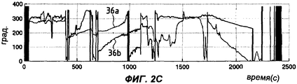
фиг.2А-2С иллюстрируют регистрацию данных, характеризующих соответственно скорость, амплитуду и фазу, которые согласно изобретению записываются в память запоминающего устройства (ЗУ),figa-2C illustrate the registration of data characterizing, respectively, the speed, amplitude and phase, which according to the invention are recorded in the memory of a storage device (memory),
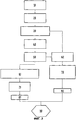
фиг.3 представляет собой органиграмму, т.е. блок-схему способа обнаружения повреждения ротора летательного аппарата в соответствии с изобретением,figure 3 is an organigram, i.e. a flowchart of a method for detecting damage to an aircraft rotor in accordance with the invention,
фиг.4 представляет собой диаграмму векторов вибрации, получаемую согласно способу по фиг.3,figure 4 is a diagram of vibration vectors obtained according to the method of figure 3,
фиг.5 представляет амплитуды векторов вибрации в зависимости от скорости согласно способу по фиг.3,figure 5 represents the amplitude of the vibration vectors depending on the speed according to the method of figure 3,
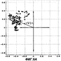
фиг.6А и 6В представляют скопления точек, представляющих декартовы координаты концов векторов вибрации и соответствующие им средние векторы для выбранного интервала скоростей согласно способу по фиг.3,figa and 6B are clusters of points representing the Cartesian coordinates of the ends of the vibration vectors and the corresponding average vectors for the selected speed range according to the method of figure 3,
на фиг.7А и 7В показаны разности векторов между средними векторами контрольного полета и средними векторами контролируемого полета согласно способу по фиг.3,on figa and 7B shows the differences of the vectors between the average vectors of the control flight and the average vectors of the controlled flight according to the method of figure 3,
на фиг.8 изображена окружность, ограничивающая пороговую зону согласно способу по фиг.3,in Fig.8 shows a circle bounding the threshold zone according to the method of Fig.3,
на фиг.9А и 9В показаны разности векторов между средними векторами контрольного полета и векторами контролируемого полета согласно способу по фиг.3,on figa and 9B shows the differences of the vectors between the average vectors of the control flight and the vectors of the controlled flight according to the method of figure 3,
фиг.10 изображает органиграмму, т.е. блок-схему варианта способа обнаружения повреждения ротора летательного аппарата в ходе полета.figure 10 depicts an organigram, i.e. flow chart of a method for detecting damage to an aircraft rotor during flight.
Сведения, подтверждающие возможность осуществления изобретения.Information confirming the possibility of carrying out the invention.
На фиг.1 изображена часть двигателя летательного аппарата, в частности турбореактивного двигателя. Турбореактивный двигатель содержит компрессор 1 низкого давления и компрессор 2 высокого давления, который подает сжатый воздух в камеру 3 сгорания для обеспечения непрерывного сгорания топлива. Газы под высоким давлением и с высокой температурой выходят с высокой скоростью через реактивное сопло (не показано). Компрессоры приводятся в действие турбиной 4, которая отбирает часть энергии сжатого газа и преобразует ее в тепло и механическую энергию.Figure 1 shows a part of the engine of an aircraft, in particular a turbojet engine. The turbojet engine comprises a low pressure compressor 1 and a
Каждый компрессор содержит вращающуюся часть, или ротор 5, неподвижную часть, или статор 6, и оболочку, или корпус 7. Ротор содержит барабан, образованный комплектом дисков, на которых укреплены подвижные лопатки 8. Статор образован несколькими рядами неподвижных лопаток, которые могут быть укреплены на корпусе 7.Each compressor contains a rotating part, or
Турбина 4 содержит одну или несколько ступеней, причем каждая ступень состоит из решетки неподвижных лопаток 9а и решетки подвижных лопаток 9b, укрепленных на диске.The turbine 4 comprises one or more stages, each stage consisting of a lattice of fixed blades 9a and a lattice of movable blades 9b mounted on a disk.
При работе турбины различные лопатки подвержены воздействию аэродинамических усилий. Кроме того, подвижные лопатки 8 и 9b подвержены воздействию центробежного усилия, которое пропорционально квадрату скорости вращения. Таким образом, лопатки и их крепление на диске рассчитываются по 5 размерам на самые тяжелые условия эксплуатации.During turbine operation, various blades are subject to aerodynamic forces. In addition, the movable blades 8 and 9b are subject to centrifugal force, which is proportional to the square of the rotation speed. Thus, the blades and their mounting on the disk are calculated in 5 sizes for the most difficult operating conditions.
Лопатка, которая представляет собой своего рода пластину, может вибрировать с собственной частотой, которая зависит от формы и размеров лопатки и вида ее крепления на диске.The blade, which is a kind of plate, can vibrate at its own frequency, which depends on the shape and size of the blade and the type of attachment to the disk.
Эта вибрация может возбуждаться вихревыми потоками, которые зарождаются на выходной кромке лопаток, механическими силами, возникающими в роторе, когда он имеет слишком большой дисбаланс, или аэродинамической нестабильностью. Создаваемая в результате этого вибрация может вызвать поломку или потерю одной или нескольких лопаток.This vibration can be excited by vortex flows, which arise at the outlet edge of the blades, by mechanical forces arising in the rotor when it has too much imbalance, or by aerodynamic instability. The vibration created as a result of this can cause breakage or loss of one or more blades.
При этом некоторые повреждения вращающихся деталей порождают резкое изменение дисбаланса соответствующего ротора и, как следствие, вибрацию.However, some damage to rotating parts give rise to a sharp change in the imbalance of the corresponding rotor and, as a result, vibration.
В общем случае вибрация двигателей отслеживается акселерометрами или другими датчиками вибрации. Каждый датчик может состоять из двух датчиков, которые образуют между собой угол, предпочтительно угол 90°, в радиальной плоскости двигателя. Датчики могут быть помещены на корпусе 7 на уровне турбины 4, одного из компрессоров 1, 2 или между компрессорами. Разумеется, предпочтительно, чтобы датчик вибрации был расположен напротив подвижного диска или дисков, подлежащих наблюдению.In general, engine vibration is monitored by accelerometers or other vibration sensors. Each sensor can consist of two sensors that form an angle between themselves, preferably an angle of 90 °, in the radial plane of the engine. The sensors can be placed on the housing 7 at the level of the turbine 4, one of the
На фиг.1 схематично показан первый датчик 12а вибрации, помещенный на уровне компрессора 2, и второй датчик 12b вибрации, помещенный на уровне турбины 4. Очевидно, что число датчиков вибрации может быть любым, а их расположение может быть различным.1 schematically shows a first vibration sensor 12a placed at the level of
Известным образом каждый датчик вибрации или иное измерительное средство подает электрический сигнал, представляющий механическую вибрацию компрессора или турбины. После усиления и фильтрации сигнал преобразуется в цифровые данные аналого-цифровым преобразователем для количественного анализа.In a known manner, each vibration sensor or other measuring means provides an electrical signal representing the mechanical vibration of a compressor or turbine. After amplification and filtering, the signal is converted into digital data by an analog-to-digital converter for quantitative analysis.
Кроме того, датчик 16 скорости измеряет скорость вращения ротора, входящего в состав компрессора, причем имеется также другой датчик скорости (не представлен), который измеряет скорость вращения ротора, входящего в состав турбины.In addition, the speed sensor 16 measures the speed of rotation of the rotor included in the compressor, and there is also another speed sensor (not shown), which measures the speed of rotation of the rotor included in the turbine.
Как очень схематично показано на фиг.1, система обнаружения повреждения в соответствии с изобретением содержит систему 22 обработки данных. В состав этой системы 22 обычным образом входит блок 23 интерфейса, который получает цифровые данные от датчиков и передает их в запоминающее устройство (ЗУ) 25 для обработки этих данных центральным блоком (ЦБ) 24. Система обработки связана с экраном и/или с принтером, которые расположены, например, в кабине летательного аппарата.As shown very schematically in FIG. 1, a damage detection system according to the invention comprises a data processing system 22. The structure of this system 22 normally includes an interface unit 23, which receives digital data from sensors and transmits them to a storage device (memory) 25 for processing this data by a central unit (CB) 24. The processing system is connected to a screen and / or a printer, which are located, for example, in the cockpit of an aircraft.
На фиг.2А-2С представлен пример данных, в соответствии с изобретением записанных в ЗУ 25 во время полета. Таким образом, ЗУ 25 является средством накопления данных, характеризующих скорость вращения ротора, а также амплитуду и фазу его вибрации, для их обработки по результатам полета.On figa-2C presents an example of data in accordance with the invention recorded in the memory 25 during flight. Thus, the memory 25 is a means of accumulating data characterizing the speed of rotation of the rotor, as well as the amplitude and phase of its vibration, for processing them according to the results of the flight.
Так, на фиг.2А представлена зависимость 32 скорости N(t) ротора от времени полета в секундах. В этом примере скорость отнесена или приведена к номинальной скорости и представлена в виде относительной скорости (в %).So, on figa presents the dependence of 32 speed N (t) of the rotor from the flight time in seconds. In this example, the speed is assigned or reduced to the nominal speed and is presented as a relative speed (in%).
Вибрация v(t) характеризуется ее амплитудой A(t), то есть максимальным отклонением относительно равновесного положения, и частотой φ(t). Таким образом, амплитуда имеет размерность длины, которая выражена здесь в микрометрах или в милах, то есть тысячных долях дюйма, а частота может быть выражена в радианах или градусах в секунду. В общем виде вибрация выражается как комплексная переменная с модулем A(t) и аргументом <φ(t) в радианах по формуле v(t)=A(t)exp(i φ(t)).The vibration v (t) is characterized by its amplitude A (t), i.e., the maximum deviation relative to the equilibrium position, and the frequency φ (t). Thus, the amplitude has a dimension of length, which is expressed here in micrometers or in miles, that is, thousandths of an inch, and the frequency can be expressed in radians or degrees per second. In general, vibration is expressed as a complex variable with modulus A (t) and argument <φ (t) in radians according to the formula v (t) = A (t) exp (i φ (t)).
Таким образом, в каждый данный момент вибрация характеризуется амплитудой и фазой или углом. Примеры по фиг.2В и 2С представляют, соответственно, амплитуду и фазу вибрации, зарегистрированные в ходе контролируемого полета.Thus, at any given moment, vibration is characterized by amplitude and phase or angle. The examples of FIGS. 2B and 2C represent, respectively, the amplitude and phase of vibration recorded during a controlled flight.
Фиг.2В показывает изменение амплитуды A(t) в милах в функции времени в секундах. Первая кривая 34а A1(t) представляет данные, измеренные первым датчиком 12а вибрации. Вторая кривая 34b A2(t) представляет данные, измеренные вторым датчиком 12b вибрации.2B shows a change in amplitude A (t) in miles as a function of time in seconds. The
Фиг.2С показывает изменение фазы φ(t) в градусах в функции времени в секундах. Первая кривая 36а фазы φ1(t) представляет данные, измеренные первым датчиком 12а вибрации. Вторая кривая 36b фазы φ2(t) представляет данные, измеренные вторым датчиком 12b вибрации.2C shows the phase change φ (t) in degrees as a function of time in seconds. The
В качестве примера частота замеров данных на фиг.2А-2С составляет 1 с-1.As an example, the data sampling rate in FIGS. 2A-2C is 1 s −1 .
Фиг.3-9В иллюстрируют способ обнаружения повреждения ротора двигателя летательного аппарата в соответствии с изобретением.3-9B illustrate a method for detecting damage to a rotor of an aircraft engine in accordance with the invention.
На фиг.3 приведена органиграмма, или блок-схема, которая иллюстрирует способ обнаружения повреждения по результатам контролируемого полета. Способ осуществляется с использованием программ, записанных в ЗУ 25 системы 22 обработки. Процесс запускается (операция, или шаг 10) считыванием данных, характеризующих скорость вращения, амплитуду и фазу вибрации ротора, записанных в ЗУ 25 во время полета.Figure 3 shows the organigram, or flowchart, which illustrates a method for detecting damage according to the results of a controlled flight. The method is carried out using programs recorded in the memory 25 of the processing system 22. The process is started (operation, or step 10) by reading data characterizing the rotation speed, amplitude and phase of vibration of the rotor recorded in the memory 25 during flight.
Таким образом, по окончании каждого полета центральный блок ЦБ считывает данные, характеризующие скорость ротора (фиг.2А), а также амплитуды (фиг.2В) и фазы (фиг.2С) вибрации, собранные различными средствами измерения.Thus, at the end of each flight, the central block of the Central Bank reads data characterizing the speed of the rotor (Fig.2A), as well as the amplitude (Fig.2B) and phase (Fig.2C) of vibration collected by various measuring instruments.
На шаге 20 вибрация в момент t выражается вектором V вибрации, который определяется по значениям амплитуды A(t) и фазы φ(t) вибрации ротора в данный момент t.At
Фиг.4 изображает в полярных координатах мгновенную диаграмму векторов V1 и V2 вибрации, полученных, соответственно, от первого и второго датчиков. Длины векторов V1 и V2 пропорциональны их модулям А1 и А2, а углы, которые они составляют с главной (координатной) осью, соответствуют их фазам φ1 и φ2.Figure 4 depicts in polar coordinates an instantaneous diagram of the vibration vectors V1 and V2 obtained, respectively, from the first and second sensors. The lengths of the vectors V1 and V2 are proportional to their modules A1 and A2, and the angles that they make up with the main (coordinate) axis correspond to their phases φ1 and φ2.
На шаге 30 (см. также фиг.5) векторы вибрации, соответствующие данным от каждого датчика вибрации, параметризуют в функции скорости ротора. После этого диапазон скорости ротора разбивают на множество интервалов скорости ротора и, соответственно, векторы вибрации группируют по этим интервалам.In step 30 (see also FIG. 5), the vibration vectors corresponding to the data from each vibration sensor are parameterized as a function of rotor speed. After that, the rotor speed range is divided into many intervals of the rotor speed and, accordingly, the vibration vectors are grouped at these intervals.
Разбиение скорости ротора не обязательно выполняется равномерным, причем каждый интервал может составлять от 1 до 10% номинальной скорости ротора. Предпочтительно делать более мелким разбиение для повышенных скоростей ротора, так как в этом диапазоне вибрация является более высокой, и, следовательно, более высок риск потери лопаток. В качестве примера, для приведенных скоростей ротора от 80% до 110% можно выбирать интервалы разбиения размером 1%.The splitting of the rotor speed is not necessarily uniform, and each interval can be from 1 to 10% of the nominal rotor speed. It is preferable to make the partition finer for higher rotor speeds, since in this range the vibration is higher, and therefore the risk of blade loss is higher. As an example, for reduced rotor speeds from 80% to 110%, partition intervals of 1% can be selected.
При этом целесообразно увеличить размер интервалов на низких скоростях и даже убрать нижнюю часть диапазона скорости, чтобы не перегружать память и не тратить время на обработку данных. Так например, можно выполнить разбиение с шагом в 2% или больше для скоростей ротора в области ниже 80% и устранить область ниже 20%.In this case, it is advisable to increase the size of the intervals at low speeds and even remove the lower part of the speed range so as not to overload the memory and not waste time processing data. For example, you can perform a split in increments of 2% or more for rotor speeds in the region below 80% and eliminate the region below 20%.
На фиг.5 показан пример распределения амплитуд (в милах) векторов, определенных по данным датчиков, в функции приведенной скорости ротора.Figure 5 shows an example of the distribution of amplitudes (in miles) of vectors determined from the sensors, as a function of the reduced rotor speed.
На шаге 40 вычисляют координаты среднего вектора <V> вибрации для каждого интервала скоростей и для каждого датчика.At
Фиг.6А представляет пример скопления (группирования) точек, представляющих декартовы координаты концов векторов вибрации, контролируемых по данным от первого датчика для выбранного интервала скоростей. В частности, на этой диаграмме представлены векторы вибрации в интервале скоростей от 80% до 82% номинальной скорости. Средний вектор <V1> вибрации в выбранном интервале может быть определен путем вычисления центра тяжести скопления точек. Следует заметить, что если число точек, представляющих координаты векторов, мало, то для повышения качества анализа предпочтительно не учитывать эти точки.6A is an example of a cluster (grouping) of points representing the Cartesian coordinates of the ends of the vibration vectors controlled by data from the first sensor for the selected speed range. In particular, this diagram shows the vibration vectors in the speed range from 80% to 82% of the nominal speed. The average vibration vector <V1> in the selected interval can be determined by calculating the center of gravity of the cluster of points. It should be noted that if the number of points representing the coordinates of the vectors is small, then to improve the quality of analysis, it is preferable not to take these points into account.
Подобным же образом фиг.6В представляет декартовы координаты векторов вибрации, контролируемых по данным от второго датчика, а также средний вектор <V2> вибрации в выбранном интервале скоростей.In a similar manner, FIG. 6B represents the Cartesian coordinates of the vibration vectors monitored from the second sensor, as well as the average vibration vector <V2> in the selected speed range.
На шаге 50 средний вектор, представляющий каждый интервал и каждый датчик, записывают в память.At
Начиная с шага 50, изменение этих векторов анализируют посредством выполнения шагов 61-81 и/или шагов 62-82.Starting at
Так, на шаге 61 для каждого интервала скоростей и для каждого датчика вычисляют разность D векторов между средним вектором <V1d> контрольного (эталонного) полета и средним вектором контролируемого полета - разумеется для одного и того же интервала скоростей. Следует отметить, что средние векторы <V1d>, представляющие различные интервалы скоростей контрольного полета, предварительно записаны в ЗУ 25 системы 22 обработки (см. фиг.1).So, in
Контрольный полет может соответствовать полету, который предшествовал контролируемому полету. В альтернативном варианте контрольный полет может соответствовать полету, связанному со стандартным контрольным двигателем, например двигателем, используемым для проведения испытаний.A control flight may correspond to a flight that preceded a controlled flight. Alternatively, the control flight may correspond to a flight associated with a standard control engine, such as the engine used for testing.
Фиг.7А иллюстрирует нахождение разности D1 векторов между средним вектором <V1d> контрольного полета, например предыдущего полета, и средним вектором <V1> контролируемого полета, то есть последнего полета, на базе данных, записанных в памяти и связанных с первым датчиком. Таким же образом фиг.7В представляет вычисление разности D2 векторов применительно ко второму датчику.7A illustrates finding the difference D1 of the vectors between the average vector <V1d> of the control flight, for example, the previous flight, and the average vector <V1> of the controlled flight, that is, the last flight, on the basis of data recorded in memory and associated with the first sensor. In the same way figv represents the calculation of the difference D2 vectors in relation to the second sensor.
В том случае, если эта разность векторов, вычисленная на шаге 61, выходит за пределы критической зоны вокруг координат конца контрольного среднего вектора, можно диагностировать, что ротор подвергся повреждению, например поломке лопатки.In the event that this difference of the vectors calculated in
На фиг.8 изображена окружность, координаты центра которой совпадают с координатами конца среднего контрольного вектора <Vd>, а радиус соответствует предварительно заданному значению, зависящему от положения датчика. Таким образом, если разность векторов выходит за пределы зоны, определяемой этой окружностью С, можно считать, что имеет место повреждение ротора. Для упрощения критерия выбора можно вычислить модуль разности векторов для его сравнения с предварительно заданной пороговой величиной.On Fig shows a circle whose center coordinates coincide with the coordinates of the end of the average control vector <Vd>, and the radius corresponds to a predefined value, depending on the position of the sensor. Thus, if the difference of the vectors goes beyond the zone defined by this circle C, we can assume that the rotor is damaged. To simplify the selection criterion, we can calculate the modulus of the difference of the vectors to compare it with a predefined threshold value.
Таким образом, на шаге 71 вычисляют модуль d каждой разности D средних векторов для каждого интервала скоростей. Затем на шаге 81 записывают в память значения этих модулей.Thus, in
Далее на шаге 90 сравнивают модуль d разности векторов с предварительно заданной пороговой величиной. Эта пороговая величина может лежать в интервале, например, от 50 до 125 мкм (от 2 до 5 мил).Next, at
На практике датчик вибрации более чувствителен к дисбалансу компрессора, чем к дисбалансу турбины. Кроме того, чувствительность датчиков зависит также от режима двигателя.In practice, the vibration sensor is more sensitive to compressor imbalance than to turbine unbalance. In addition, the sensitivity of the sensors also depends on the engine mode.
В качестве примера, чувствительность датчика колеблется примерно от 200 см·г/мил до 300 см·г/мил, то есть мгновенный дисбаланс, составляющий примерно 200 см·г, соответствует амплитуде вибрации в 1 мил (25 мкм).As an example, the sensitivity of the sensor ranges from about 200 cm · g / mil to 300 cm · g / mil, that is, an instantaneous imbalance of about 200 cm · g corresponds to a vibration amplitude of 1 mil (25 μm).
В общем случае поломка лопатки вызывает дисбаланс, примерно равный 2000 см·г. Таким образом, с учетом нормального остаточного дисбаланса и различной чувствительности датчиков поломка лопатки соответствует изменению амплитуды вибрации в пределах от 50 до 125 мкм (от 2 до 5 мил). Следует отметить, что диапазон колебаний пороговой величины может изменяться в зависимости от модели двигателя.In general, a broken blade causes an imbalance of approximately 2000 cm · g. Thus, taking into account the normal residual imbalance and the different sensitivity of the sensors, the breakage of the blade corresponds to a change in the amplitude of vibration in the range from 50 to 125 μm (from 2 to 5 mils). It should be noted that the range of fluctuations of the threshold value may vary depending on the model of the engine.
Далее будет описан процесс вычисления статистического разброса векторов со ссылками на операции 62-82. Так, на шаге 62 (см. также фиг.9А и 9В) вычисляют среднеквадратичное векторное отклонение каждого вектора, определенного ранее на шаге 30, в выбранном интервале скоростей. Таким образом, в этом интервале скоростей вычисляют разность векторов между каждым вектором V1 или V2 вибрации (определенном на шаге 30) контролируемого полета и средним вектором <V1d> или <V2d> вибрации (предварительно записанным в памяти) контрольного полета для одного и того же интервала скоростей ротора.Next, the process of calculating the statistical spread of vectors will be described with reference to operations 62-82. So, in step 62 (see also FIGS. 9A and 9B), the root-mean-square vector deviation of each vector determined earlier in
Следует отметить, что на шаге 62 также можно вычислить разницу векторов между каждым вектором вибрации (контролируемым на шаге 30) контролируемого полета и средним вектором вибрации (записанным в памяти на шаге 50) этого же контролируемого полета для того же интервала скоростей ротора.It should be noted that in
Далее, на шаге 72 вычисляют модуль разности векторов, связанной с каждым вектором вибрации, и определяют максимальный модуль dmax1 или dmax2. Затем, на шаге 82, максимальный модуль, то есть модуль наибольшей разности векторов в анализируемом интервале скоростей, записывают в память.Next, in
После этого на шаге 90 сравнивают наибольший модуль в анализируемом интервале скоростей с предварительно заданной пороговой величиной.After that, at
В том случае, если наибольший модуль (записанный в памяти на шаге 82) или модуль разности векторов (записанный в памяти на шаге 81) превышает предварительно заданную пороговую величину, сигнал тревоги подается на экран или на принтер в кабине для привлечения внимания технического персонала. При этом должно быть произведено соответствующее обследование двигателя перед его повторным запуском.In the event that the largest module (recorded in memory in step 82) or the vector difference module (recorded in memory in step 81) exceeds a predetermined threshold value, an alarm signal is sent to the screen or to the printer in the cab to attract the attention of technical personnel. In this case, an appropriate examination of the engine should be made before it is restarted.
С другой стороны, если наибольший модуль или модуль разности векторов не превышает предварительно заданной пороговой величины, производят обновление средних векторов контрольного полета на базе данных контролируемого полета для оценки нормального изменения двигателя.On the other hand, if the largest module or module of the vector difference does not exceed a predetermined threshold value, the average vectors of the control flight are updated on the basis of the controlled flight data to evaluate the normal engine change.
Может быть также предусмотрено, что данные, характеризующие скорость и вибрации ротора, сохраняют на съемном носителе данных для последующей обработки этих данных компьютером на земле после посадки летательного аппарата.It may also be provided that data characterizing the speed and vibration of the rotor are stored on a removable storage medium for subsequent processing of these data by a computer on the ground after landing of the aircraft.
Способ обнаружения повреждения ротора двигателя летательного аппарата, содержащий описанные выше операции и выполняемый по результатам контролируемого полета, дает особые преимущества, которые состоят в том, что внимание пилота не отвлекается на несущественные проблемы. Другое преимущество состоит в том, что не происходит перегрузки управляющей бортовой системы летательного аппарата.The method for detecting damage to the rotor of an aircraft engine, containing the operations described above and carried out according to the results of a controlled flight, gives special advantages, which consist in the fact that the pilot's attention is not distracted by minor problems. Another advantage is that the control system of the aircraft is not overloaded.
С помощью настоящего изобретения вполне возможно также обнаруживать повреждение ротора в ходе полета посредством способа, подобного способу по фиг.3.Using the present invention, it is also possible to detect rotor damage during flight by a method similar to the method of FIG. 3.
Операции блок-схемы, показанной на фиг.10 и соответствующей данному варианту способа, подобны операциям (шагам), показанным на фиг.3, за исключением того, что способ запускается на шаге 110 считыванием в режиме реального времени данных, характеризующих скорость ротора, а также амплитуду и фазу его вибрации. На шаге 120 вибрацию выражают посредством вектора, который определяют применительно к выбранному интервалу скоростей ротора (шаг 130). В отличие от способа по фиг.3, на шаге 140 координаты среднего вектора вибрации для выбранного интервала скоростей вычисляют на основе частичных данных, собранных на шаге 110. Таким образом, средний вектор может изменяться в ходе полета, обогащаясь последующими данными. На шаге 150 каждый вычисленный средний вектор записывают в память взамен среднего вектора, ранее записанного для того же интервала скоростей. Все остальные операции подобны тем, которые были описаны выше в способе по фиг.3.The operations of the flowchart shown in Fig. 10 and corresponding to this variant of the method are similar to the operations (steps) shown in Fig. 3, except that the method is started in
Claims (13)
Applications Claiming Priority (2)
| Application Number | Priority Date | Filing Date | Title |
|---|---|---|---|
| FR0206530 | 2002-05-28 | ||
| FR0206530A FR2840358B1 (en) | 2002-05-28 | 2002-05-28 | METHOD AND SYSTEM FOR DETECTING ROTOR DAMAGE OF AN AIRCRAFT ENGINE |
Publications (2)
| Publication Number | Publication Date |
|---|---|
| RU2003116164A RU2003116164A (en) | 2004-11-20 |
| RU2320969C2 true RU2320969C2 (en) | 2008-03-27 |
Family
ID=29415135
Family Applications (1)
| Application Number | Title | Priority Date | Filing Date |
|---|---|---|---|
| RU2003116164/06A RU2320969C2 (en) | 2002-05-28 | 2003-05-26 | Method and system of finding faults in flying vehicle engine rotor and flying vehicle engine |
Country Status (9)
| Country | Link |
|---|---|
| US (1) | US6918747B2 (en) |
| EP (1) | EP1367226B1 (en) |
| JP (1) | JP4111869B2 (en) |
| CA (1) | CA2430153C (en) |
| DE (1) | DE60307926T2 (en) |
| ES (1) | ES2269942T3 (en) |
| FR (1) | FR2840358B1 (en) |
| RU (1) | RU2320969C2 (en) |
| UA (1) | UA82462C2 (en) |
Cited By (2)
| Publication number | Priority date | Publication date | Assignee | Title |
|---|---|---|---|---|
| RU2507403C2 (en) * | 2008-10-10 | 2014-02-20 | Снекма | Method and system for turbojet control |
| RU2686654C2 (en) * | 2014-10-22 | 2019-04-29 | Сафран Эркрафт Энджинз | Method and device for aircraft engine impeller monitoring by measuring equilibrium position |
Families Citing this family (35)
| Publication number | Priority date | Publication date | Assignee | Title |
|---|---|---|---|---|
| DE102005009557A1 (en) * | 2005-03-02 | 2006-09-07 | Siemens Ag | Imbalance detection method for use in detecting the steady mounting of a rotary system, e.g. a CT system, in which sets of measurements of the rotation of the system are taken, and their scatter compared with a threshold value |
| US20070245746A1 (en) * | 2006-04-21 | 2007-10-25 | Mollmann Daniel E | Methods and systems for detecting rotor assembly speed oscillation in turbine engines |
| US8818683B2 (en) * | 2006-04-21 | 2014-08-26 | General Electric Company | Method and apparatus for operating a gas turbine engine |
| US20070272023A1 (en) * | 2006-05-23 | 2007-11-29 | Honeywell International Inc. | Electronic vibration sensor |
| US7839304B2 (en) * | 2008-05-01 | 2010-11-23 | The United States Of America As Represented By The Secretary Of The Navy | Method and system for alerting aircrew to unsafe vibration levels |
| FR2932850B1 (en) * | 2008-06-23 | 2010-08-13 | Snecma | METHOD AND SYSTEM FOR DETERMINING THE ANGULAR POSITION OF A TURBOJET ROTOR |
| US7941281B2 (en) * | 2008-12-22 | 2011-05-10 | General Electric Company | System and method for rotor blade health monitoring |
| FR2941049B1 (en) * | 2009-01-13 | 2011-02-11 | Snecma | METHOD AND SYSTEM FOR MONITORING VIBRATION PHENOMENA IN AN AIRCRAFT GAS TURBINE ENGINE IN OPERATION |
| GB0902730D0 (en) | 2009-02-18 | 2009-04-01 | Oxford Biosignals Ltd | Method and apparatus for monitoring and analyzing vibrations in rotary machines |
| FR2946387B1 (en) * | 2009-06-05 | 2011-07-08 | Snecma | DEVICE AND METHOD FOR DETECTING A FAILURE OF A LOW PRESSURE FUEL PUMP OF A TURBOJET AND TURBOJET ENGINE WITH SAID DEVICE |
| FR2956159B1 (en) * | 2010-02-08 | 2012-02-10 | Snecma | METHOD FOR AUTOMATED DETECTION OF INGESTION OF AT LEAST ONE FOREIGN BODY BY A GAS TURBINE ENGINE |
| US8752394B2 (en) * | 2010-03-15 | 2014-06-17 | Rolls-Royce Corporation | Determining fan parameters through pressure monitoring |
| KR101101974B1 (en) * | 2010-06-14 | 2012-01-02 | 인하대학교 산학협력단 | System for fault detection and diagnosis of aircraft engine and method thereof |
| EP2594912A1 (en) | 2011-11-21 | 2013-05-22 | Eurocopter Deutschland GmbH | Detection system for detection of damages on rotating components of aircraft and method of operating such a detection system |
| US8720275B2 (en) * | 2012-01-04 | 2014-05-13 | General Electric Company | Detecting rotor anomalies |
| FR2988130B1 (en) * | 2012-03-13 | 2014-05-09 | Snecma | DEFECT DETECTION SYSTEM ON AN AIRCRAFT ENGINE BEARING WHEEL |
| US9587512B1 (en) * | 2012-05-08 | 2017-03-07 | The Boeing Company | Method for balancing a turbofan engine or other rotating system |
| CN103808515B (en) * | 2012-11-12 | 2016-08-03 | 中航商用航空发动机有限责任公司 | Blade segregation apparatus and electromotor including experiment device |
| GB201302815D0 (en) | 2013-02-19 | 2013-04-03 | Rolls Royce Plc | Determining the deterioration of a gas turbine engine in use |
| US9840935B2 (en) | 2014-03-31 | 2017-12-12 | United Technologies Corporation | Rotating machinery monitoring system |
| EP2933616A1 (en) * | 2014-04-15 | 2015-10-21 | Siemens Aktiengesellschaft | Method for determining damage in turbine blades |
| US10908014B2 (en) | 2014-08-21 | 2021-02-02 | Baker Hughes, A Ge Company, Llc | Detecting rotor anomalies during transient speed operations |
| FR3035982B1 (en) * | 2015-05-05 | 2017-04-14 | Snecma | METHOD FOR MONITORING AN AIRCRAFT ENGINE IN OPERATION DURING A FLIGHT |
| FR3039217B1 (en) * | 2015-07-22 | 2017-07-21 | Snecma | AIRCRAFT COMPRISING A TURBOMACHINE INTEGRATED WITH REAR FUSELAGE COMPRISING A SYSTEM FOR BLOCKING BLOWERS |
| US10718689B2 (en) | 2016-12-22 | 2020-07-21 | General Electric Company | Modeling and visualization of vibration mechanics in residual space |
| US20180216484A1 (en) * | 2017-01-31 | 2018-08-02 | General Electric Company | Systems and methods to detect a fluid induced instability condition in a turbomachine |
| FR3064064B1 (en) * | 2017-03-20 | 2021-09-17 | Safran Aircraft Engines | TURBOMACHINE ROTOR BALANCING |
| FR3064070B1 (en) * | 2017-03-20 | 2021-02-26 | Safran Aircraft Engines | PROCESS FOR MONITORING THE ENGINES OF AN AIRCRAFT |
| CN107269512A (en) * | 2017-07-26 | 2017-10-20 | 青岛海尔股份有限公司 | A kind of compressor noise detection means and its method for detecting compressor noise |
| RU2680770C1 (en) * | 2018-06-25 | 2019-02-26 | Акционерное общество "Научно-исследовательский и конструкторский институт центробежных и роторных компрессоров им. В.Б. Шнеппа" | Incompressible objects into the turbo compressor flow part detection method and system for its implementation |
| CN111238804B (en) * | 2018-11-28 | 2021-08-03 | 中国航发商用航空发动机有限责任公司 | Test piece configuration method for over-rotation rupture test of aircraft engine rotor |
| CN110907186B (en) * | 2019-11-08 | 2020-12-25 | 北京化工大学 | Rotor vibration phase measuring and calculating method for aeroengine test bed |
| GB201918094D0 (en) * | 2019-12-10 | 2020-01-22 | Rolls Royce Plc | Methods and apparatus for inspecting an engine |
| GB201918095D0 (en) | 2019-12-10 | 2020-01-22 | Rolls Royce Plc | Methods and apparatus for inspecting an engine |
| FR3125589B1 (en) * | 2021-07-26 | 2023-10-20 | Safran Aircraft Engines | Device for measuring vibrations in a turbomachine |
Family Cites Families (16)
| Publication number | Priority date | Publication date | Assignee | Title |
|---|---|---|---|---|
| US4303882A (en) * | 1979-10-19 | 1981-12-01 | General Electric Company | Method and apparatus for monitoring torsional vibration in the rotor of a dynamoelectric machine |
| JPS56130634A (en) * | 1980-03-19 | 1981-10-13 | Hitachi Ltd | Method and device for monitoring oscillation of rotary machine |
| US4453407A (en) * | 1980-04-17 | 1984-06-12 | Hitachi, Ltd. | Vibration diagnosis method and apparatus for rotary machines |
| JPS58150859A (en) * | 1982-03-03 | 1983-09-07 | Hitachi Ltd | Method and apparatus for diagnosing crack of rotor |
| US5258923A (en) * | 1987-07-22 | 1993-11-02 | General Electric Company | System and method for detecting the occurrence, location and depth of cracks in turbine-generator rotors |
| US4955269A (en) * | 1988-02-04 | 1990-09-11 | Westinghouse Electric Corp. | Turbine blade fatigue monitor |
| US5148711A (en) * | 1990-11-01 | 1992-09-22 | Westinghouse Electric Corp. | Apparatus and method for removing common mode vibration data from digital turbine blade vibration data |
| ES2148235T3 (en) * | 1992-08-10 | 2000-10-16 | Dow Deutschland Inc | PROCEDURE AND DEVICE FOR MONITORING THE VIBRATIONAL EXCITATION OF AN AXIAL COMPRESSOR. |
| US5544073A (en) * | 1994-06-02 | 1996-08-06 | Computational Systems, Inc. | Rotor balancing calculator |
| US5686669A (en) * | 1996-02-29 | 1997-11-11 | Monitoring Technology Corporation | Apparatus and method for analyzing the condition and performance of turbomachines by processing signals representing rotor motion |
| US5744723A (en) * | 1996-05-10 | 1998-04-28 | Csi Technology, Inc. | Method for determining rotational speed from machine vibration data |
| US6098022A (en) * | 1997-10-17 | 2000-08-01 | Test Devices, Inc. | Detecting anomalies in rotating components |
| US6263738B1 (en) * | 1999-08-25 | 2001-07-24 | General Electric Company | Vibration phasor monitoring system for rotating members |
| US6321602B1 (en) * | 1999-09-28 | 2001-11-27 | Rockwell Science Center, Llc | Condition based monitoring by vibrational analysis |
| US6505143B1 (en) * | 2000-01-20 | 2003-01-07 | General Electric Company | Machine protection system for rotating equipment and method |
| US6445995B1 (en) * | 2001-01-26 | 2002-09-03 | General Electric Company | Vibration sensing in gas turbine engine |
-
2002
- 2002-05-28 FR FR0206530A patent/FR2840358B1/en not_active Expired - Fee Related
-
2003
- 2003-05-23 EP EP03291230A patent/EP1367226B1/en not_active Expired - Lifetime
- 2003-05-23 ES ES03291230T patent/ES2269942T3/en not_active Expired - Lifetime
- 2003-05-23 DE DE60307926T patent/DE60307926T2/en not_active Expired - Lifetime
- 2003-05-26 RU RU2003116164/06A patent/RU2320969C2/en active
- 2003-05-27 JP JP2003149102A patent/JP4111869B2/en not_active Expired - Fee Related
- 2003-05-28 UA UA2003054893A patent/UA82462C2/en unknown
- 2003-05-28 CA CA2430153A patent/CA2430153C/en not_active Expired - Fee Related
- 2003-05-28 US US10/445,935 patent/US6918747B2/en not_active Expired - Fee Related
Cited By (2)
| Publication number | Priority date | Publication date | Assignee | Title |
|---|---|---|---|---|
| RU2507403C2 (en) * | 2008-10-10 | 2014-02-20 | Снекма | Method and system for turbojet control |
| RU2686654C2 (en) * | 2014-10-22 | 2019-04-29 | Сафран Эркрафт Энджинз | Method and device for aircraft engine impeller monitoring by measuring equilibrium position |
Also Published As
| Publication number | Publication date |
|---|---|
| JP4111869B2 (en) | 2008-07-02 |
| FR2840358A1 (en) | 2003-12-05 |
| US20040060347A1 (en) | 2004-04-01 |
| CA2430153C (en) | 2011-01-11 |
| DE60307926T2 (en) | 2007-09-20 |
| CA2430153A1 (en) | 2003-11-28 |
| ES2269942T3 (en) | 2007-04-01 |
| UA82462C2 (en) | 2008-04-25 |
| FR2840358B1 (en) | 2006-09-15 |
| JP2004036615A (en) | 2004-02-05 |
| EP1367226A1 (en) | 2003-12-03 |
| DE60307926D1 (en) | 2006-10-12 |
| US6918747B2 (en) | 2005-07-19 |
| EP1367226B1 (en) | 2006-08-30 |
Similar Documents
| Publication | Publication Date | Title |
|---|---|---|
| RU2320969C2 (en) | Method and system of finding faults in flying vehicle engine rotor and flying vehicle engine | |
| US7591183B2 (en) | Gas turbine engine with a plurality of bleed valves | |
| US6456945B1 (en) | Detecting anomalies in rotating components | |
| CN104075795B (en) | Method and system for monitoring vibration state of impeller of wind generating set | |
| CN101592590B (en) | Fault indirect diagnosis technique of rotating blade | |
| EP2547893B1 (en) | Determining fan parameters through pressure monitoring | |
| US20130268154A1 (en) | Detection system for detection of damages on rotating components of components of aircraft and method of operating such a detection system | |
| KR101718251B1 (en) | Method and system for monitoring rotating blade health | |
| US8313279B2 (en) | Dual rotor vibration monitoring | |
| US7698942B2 (en) | Turbine engine stall warning system | |
| US6904371B2 (en) | Method and apparatus for measuring rotor unbalance | |
| JP2012013079A (en) | System and method for monitoring health of airfoil | |
| JP2012013082A (en) | System and method for monitoring health of airfoil | |
| US10858122B2 (en) | Propeller health monitoring | |
| Krause et al. | Asynchronous response analysis of non-contact vibration measurements on compressor rotor blades | |
| Barragán et al. | Engine vibration monitoring and diagnosis based on on-board captured data | |
| EP4123127A1 (en) | Fan icing detection system | |
| KR20110130292A (en) | Method of detecting failure of aeroplane engine and apparatus for detecting failure of aeroplane engine performing the same | |
| JPH05113103A (en) | Monitoring device for operation state of stationary blade and rotor blade |
Legal Events
| Date | Code | Title | Description |
|---|---|---|---|
| PC41 | Official registration of the transfer of exclusive right |
Effective date: 20130802 |
|
| PD4A | Correction of name of patent owner |