RU2507403C2 - Method and system for turbojet control - Google Patents
Method and system for turbojet control Download PDFInfo
- Publication number
- RU2507403C2 RU2507403C2 RU2011118448/06A RU2011118448A RU2507403C2 RU 2507403 C2 RU2507403 C2 RU 2507403C2 RU 2011118448/06 A RU2011118448/06 A RU 2011118448/06A RU 2011118448 A RU2011118448 A RU 2011118448A RU 2507403 C2 RU2507403 C2 RU 2507403C2
- Authority
- RU
- Russia
- Prior art keywords
- signal
- rotor
- amplitude
- turbojet engine
- time window
- Prior art date
Links
Images


Classifications
-
- F—MECHANICAL ENGINEERING; LIGHTING; HEATING; WEAPONS; BLASTING
- F01—MACHINES OR ENGINES IN GENERAL; ENGINE PLANTS IN GENERAL; STEAM ENGINES
- F01D—NON-POSITIVE DISPLACEMENT MACHINES OR ENGINES, e.g. STEAM TURBINES
- F01D21/00—Shutting-down of machines or engines, e.g. in emergency; Regulating, controlling, or safety means not otherwise provided for
- F01D21/003—Arrangements for testing or measuring
-
- F—MECHANICAL ENGINEERING; LIGHTING; HEATING; WEAPONS; BLASTING
- F01—MACHINES OR ENGINES IN GENERAL; ENGINE PLANTS IN GENERAL; STEAM ENGINES
- F01D—NON-POSITIVE DISPLACEMENT MACHINES OR ENGINES, e.g. STEAM TURBINES
- F01D21/00—Shutting-down of machines or engines, e.g. in emergency; Regulating, controlling, or safety means not otherwise provided for
- F01D21/04—Shutting-down of machines or engines, e.g. in emergency; Regulating, controlling, or safety means not otherwise provided for responsive to undesired position of rotor relative to stator or to breaking-off of a part of the rotor, e.g. indicating such position
-
- G—PHYSICS
- G01—MEASURING; TESTING
- G01H—MEASUREMENT OF MECHANICAL VIBRATIONS OR ULTRASONIC, SONIC OR INFRASONIC WAVES
- G01H1/00—Measuring characteristics of vibrations in solids by using direct conduction to the detector
- G01H1/003—Measuring characteristics of vibrations in solids by using direct conduction to the detector of rotating machines
- G01H1/006—Measuring characteristics of vibrations in solids by using direct conduction to the detector of rotating machines of the rotor of turbo machines
-
- F—MECHANICAL ENGINEERING; LIGHTING; HEATING; WEAPONS; BLASTING
- F05—INDEXING SCHEMES RELATING TO ENGINES OR PUMPS IN VARIOUS SUBCLASSES OF CLASSES F01-F04
- F05D—INDEXING SCHEME FOR ASPECTS RELATING TO NON-POSITIVE-DISPLACEMENT MACHINES OR ENGINES, GAS-TURBINES OR JET-PROPULSION PLANTS
- F05D2260/00—Function
- F05D2260/80—Diagnostics
-
- F—MECHANICAL ENGINEERING; LIGHTING; HEATING; WEAPONS; BLASTING
- F05—INDEXING SCHEMES RELATING TO ENGINES OR PUMPS IN VARIOUS SUBCLASSES OF CLASSES F01-F04
- F05D—INDEXING SCHEME FOR ASPECTS RELATING TO NON-POSITIVE-DISPLACEMENT MACHINES OR ENGINES, GAS-TURBINES OR JET-PROPULSION PLANTS
- F05D2260/00—Function
- F05D2260/96—Preventing, counteracting or reducing vibration or noise
-
- F—MECHANICAL ENGINEERING; LIGHTING; HEATING; WEAPONS; BLASTING
- F05—INDEXING SCHEMES RELATING TO ENGINES OR PUMPS IN VARIOUS SUBCLASSES OF CLASSES F01-F04
- F05D—INDEXING SCHEME FOR ASPECTS RELATING TO NON-POSITIVE-DISPLACEMENT MACHINES OR ENGINES, GAS-TURBINES OR JET-PROPULSION PLANTS
- F05D2270/00—Control
- F05D2270/01—Purpose of the control system
- F05D2270/09—Purpose of the control system to cope with emergencies
-
- F—MECHANICAL ENGINEERING; LIGHTING; HEATING; WEAPONS; BLASTING
- F05—INDEXING SCHEMES RELATING TO ENGINES OR PUMPS IN VARIOUS SUBCLASSES OF CLASSES F01-F04
- F05D—INDEXING SCHEME FOR ASPECTS RELATING TO NON-POSITIVE-DISPLACEMENT MACHINES OR ENGINES, GAS-TURBINES OR JET-PROPULSION PLANTS
- F05D2270/00—Control
- F05D2270/30—Control parameters, e.g. input parameters
- F05D2270/304—Spool rotational speed
-
- Y—GENERAL TAGGING OF NEW TECHNOLOGICAL DEVELOPMENTS; GENERAL TAGGING OF CROSS-SECTIONAL TECHNOLOGIES SPANNING OVER SEVERAL SECTIONS OF THE IPC; TECHNICAL SUBJECTS COVERED BY FORMER USPC CROSS-REFERENCE ART COLLECTIONS [XRACs] AND DIGESTS
- Y02—TECHNOLOGIES OR APPLICATIONS FOR MITIGATION OR ADAPTATION AGAINST CLIMATE CHANGE
- Y02T—CLIMATE CHANGE MITIGATION TECHNOLOGIES RELATED TO TRANSPORTATION
- Y02T50/00—Aeronautics or air transport
- Y02T50/60—Efficient propulsion technologies, e.g. for aircraft
Landscapes
- Engineering & Computer Science (AREA)
- Mechanical Engineering (AREA)
- General Engineering & Computer Science (AREA)
- Physics & Mathematics (AREA)
- General Physics & Mathematics (AREA)
- Measurement Of Mechanical Vibrations Or Ultrasonic Waves (AREA)
- Testing Of Devices, Machine Parts, Or Other Structures Thereof (AREA)
- Control Of Turbines (AREA)
- Testing Of Engines (AREA)
Abstract
Description
Предшествующий уровень техникиState of the art
Настоящее изобретение относится к общей области контроля турбореактивного двигателя. В частности, оно касается способа и системы, позволяющих автоматически обнаруживать попадание постороннего предмета в турбореактивный двигатель самолета во время полета.The present invention relates to the general field of turbojet control. In particular, it relates to a method and system that automatically detects the ingress of a foreign object into an aircraft turbojet engine during a flight.
Во время полета в турбореактивный двигатель могут попадать посторонние предметы или детали, отделившиеся от турбореактивного двигателя, которые могут привести к повреждениям внутри этого двигателя. В частности, столкновение предмета с лопаткой вентилятора может привести к ее повреждению. В случае повреждений, связанных с попаданием посторонних предметов в турбореактивный двигатель (например, птиц), говорят о повреждениях FOD (от “Foreign Object Damage”). В случае повреждений, связанных с попаданием отделившихся деталей турбореактивного двигателя (например, заклепок, болтов и т.д.), говорят о повреждениях DOD (от “Domestic Object Damage”).During the flight, foreign objects or parts that are separated from the turbojet engine may enter the turbojet engine, which can lead to damage inside the engine. In particular, collision of an object with a fan blade may result in damage. In the event of damage due to the ingress of foreign objects into the turbojet engine (for example, birds), FOD damage (from “Foreign Object Damage”) is said to be. In the event of damage associated with the release of separated parts of a turbojet (for example, rivets, bolts, etc.), DOD damage (from “Domestic Object Damage”) is referred to.
Известны различные решения для обнаружения повреждений FOD или DOD. Одно из этих решений основано на измерении вибраций одного из роторов турбореактивного двигателя для обнаружения появления дисбаланса в результате его повреждения при попадании предмета. В случае обнаружения дисбаланса осуществляют визуальный осмотр турбореактивного двигателя на земле (например, при помощи эндоскопии): присутствие следов удара, перьев птиц или выемок на лопатках в месте удара позволяет, таким образом, диагностировать наличие повреждений FOD или DOD.Various solutions are known for detecting FOD or DOD damage. One of these solutions is based on measuring the vibrations of one of the rotors of a turbojet engine to detect the appearance of an imbalance as a result of damage to it when an object hits. In the event of imbalance, a visual inspection of the turbojet engine on the ground is carried out (for example, using endoscopy): the presence of impact marks, bird feathers or notches on the shoulder blades at the site of impact allows, therefore, to diagnose the presence of FOD or DOD damage.
Однако такое решение имеет целый ряд недостатков. В частности, оно не позволяет обнаруживать наличие повреждений FOD или DOD, которые не приводят к дисбалансу на роторах турбореактивного двигателя (или приводят к слишком незначительному дисбалансу, чтобы его можно было обнаружить). Кроме того, визуальный осмотр турбореактивного двигателя требует вмешательства на земле, которое необходимо планировать заранее и которое может оказаться затратным по времени.However, this solution has a number of disadvantages. In particular, it does not detect FOD or DOD damage that does not result in an imbalance on the rotors of a turbojet engine (or lead to too little imbalance to be detected). In addition, visual inspection of a turbojet engine requires ground intervention, which must be planned ahead of time and which may be time consuming.
Другое известное решение состоит в использовании измерительных инструментов, установленных на борту самолета (таких как радары), для обнаружений повреждений FOD или DOD. Недостатком этого решения является необходимость установки дополнительных инструментов, которая по сравнению с получаемым выигрышем является дорогой и приводит к увеличению массы самолета.Another known solution is to use measuring instruments mounted on board an aircraft (such as radars) to detect FOD or DOD damage. The disadvantage of this solution is the need to install additional tools, which, compared with the gain, is expensive and leads to an increase in the mass of the aircraft.
Из документа US 2007/0250245 известен также способ контроля турбореактивного двигателя, позволяющий практически моментально обнаруживать повреждение турбореактивного двигателя в результате попадания в него постороннего предмета. Для этого, согласно указанному способу, в режиме реального времени сравнивают вибрационный уровень ротора турбореактивного двигателя с заранее определенным порогом. В случае превышения этого порога в течение заранее определенного времени подается тревожный сигнал о необходимости проведения обслуживания.From the document US 2007/0250245 there is also known a method for monitoring a turbojet engine, which allows almost instantly detect damage to the turbojet engine as a result of a foreign object falling into it. For this, according to the specified method, the vibrational level of the rotor of a turbojet engine is compared in real time with a predetermined threshold. If this threshold is exceeded for a predetermined time, an alarm is given indicating the need for maintenance.
Однако этот способ имеет несколько недостатков. В частности, он ограничен обнаружением повреждений FOD или DOD, которые, по меньшей мере, временно привели к деформации лопатки вентилятора (способ обрабатывает только ограниченные вибрационные данные). Таким образом, способ не позволяет обнаружить простой удар при попадании постороннего тела без деформации (временной или окончательной) лопатки вентилятора. Кроме того, для выдачи тревожного сигнала о необходимости обслуживания необходимо, чтобы превышение порога произошло за минимальное время. Поэтому существует риск того, что некоторые повреждения FOD или DOD не будут обнаружены при помощи этого способа. Наконец, способ не предусматривает возможности предотвращения ложных тревог путем устранения электронных помех сигнала.However, this method has several disadvantages. In particular, it is limited to detecting FOD or DOD damage that at least temporarily leads to deformation of the fan blade (the method processes only limited vibration data). Thus, the method does not allow to detect a simple blow when a foreign body enters without deformation (temporary or final) of the fan blade. In addition, to generate an alarm about the need for maintenance, it is necessary that the threshold is exceeded in a minimum time. Therefore, there is a risk that some damage to the FOD or DOD will not be detected using this method. Finally, the method does not provide the possibility of preventing false alarms by eliminating the electronic interference of the signal.
Из документа US 6,907,368 известен также способ обнаружения попадания отделившихся деталей (DOD) путем анализа, при помощи преобразования Фурье, сигнала, характерного для шума турбореактивного двигателя во время работы. Несмотря на свою эффективность при обнаружении повреждений DOD, этот способ имеет тот недостаток, что не позволяет избежать ложных тревог, вызванных возмущениями, причиной которых не является попадание в двигатель отделившихся деталей.From the document US 6,907,368 there is also known a method for detecting the ingress of separated parts (DOD) by analysis, using the Fourier transform, of the signal characteristic of the noise of a turbojet during operation. Despite its effectiveness in detecting DOD damage, this method has the disadvantage that it does not allow avoiding false alarms caused by disturbances that are not caused by the separation of detached parts into the engine.
Объект и сущность изобретенияThe object and essence of the invention
Таким образом, настоящее изобретение призвано устранить такие недостатки и предложить надежное автоматическое обнаружение повреждений FOD или DOD, даже если они не приводят к появлению дисбаланса на одном из роторов турбореактивного двигателя или к деформации лопатки вентилятора.Thus, the present invention is intended to eliminate such drawbacks and offer reliable automatic detection of FOD or DOD damage, even if they do not lead to an imbalance on one of the rotors of the turbojet engine or to deformation of the fan blade.
В связи с этим объектом настоящего изобретения является способ контроля турбореактивного двигателя, состоящий в том, что:In this regard, an object of the present invention is a method for controlling a turbojet engine, comprising:
получают сигнал, характерный для вибрационного уровня ротора во время работы турбореактивного двигателя;receive a signal characteristic of the vibrational level of the rotor during operation of the turbojet engine;
получают режим вращения ротора во время работы;get the rotation mode of the rotor during operation;
сравнивают амплитуду сигнала, по меньшей мере, с одним заранее определенным вибрационным порогом в зависимости от режима вращения ротора; иcomparing the amplitude of the signal with at least one predetermined vibration threshold depending on the mode of rotation of the rotor; and
в случае превышения порога пиком амплитуды анализируют сигнал во временном окне, образованном вокруг пика амплитуды, чтобы определить, является ли явление, ставшее причиной пика амплитуды, механическим ударом, которому подвергся ротор турбореактивного двигателя или электронное возмущение сигнала.if the threshold is exceeded by the amplitude peak, the signal is analyzed in a time window formed around the amplitude peak to determine whether the phenomenon that caused the amplitude peak is a mechanical shock to which the rotor of the turbojet engine or electronic disturbance of the signal is subjected.
Способ в соответствии с настоящим изобретением содержит этап анализа сигнала после обнаружения превышения вибрационного порога пиком амплитуды. Целью этого этапа является определение того, что явлением, вызвавшим пик амплитуды, является именно механический удар, которому подвергся ротор турбореактивного двигателя, а не простое электронное возмущение сигнала. Таким образом, можно устранить любую ложную тревогу.The method in accordance with the present invention comprises the step of analyzing the signal after detecting that the vibration threshold is exceeded by a peak amplitude. The purpose of this stage is to determine that the phenomenon that caused the peak in amplitude is precisely the mechanical shock to which the rotor of the turbojet engine was subjected, and not a simple electronic signal perturbation. In this way, any false alarm can be eliminated.
Кроме того, способ в соответствии с настоящим изобретением позволяет производить обнаружение самых разных явлений, приводящих к пику амплитуды: таким образом, не обязательно, чтобы предмет, попавший в турбореактивный двигатель, вызывал дисбаланс или приводил к деформации (даже временной) лопатки вентилятора, чтобы его можно было обнаружить.In addition, the method in accordance with the present invention allows the detection of a variety of phenomena leading to a peak in amplitude: thus, it is not necessary that an object caught in a turbojet engine causes an imbalance or deformation (even temporary) of the fan blade so that it could be discovered.
В целом способ в соответствии с настоящим изобретением обеспечивает передачу сообщения обслуживания для предписания визуального осмотра реальных повреждений, вызванных попаданием предмета в турбореактивный двигатель (например, в конце полета), не дожидаясь заранее запланированного технического осмотра. Таким образом, можно избежать долгосрочного ухудшения характеристик турбореактивного двигателя и максимально быстро устранить повреждения, появившиеся в результате попадания постороннего предмета.In general, the method in accordance with the present invention transmits a service message to prescribe a visual inspection of actual damage caused by an object falling into a turbojet engine (for example, at the end of a flight) without waiting for a pre-scheduled inspection. Thus, it is possible to avoid long-term deterioration in the performance of a turbojet engine and as quickly as possible to eliminate damage resulting from a foreign object.
Наконец, способ в соответствии с настоящим изобретением можно применять при помощи измерительных инструментов (в частности, акселерометров) или систем сбора данных (в частности, электронного вычислителя), уже присутствующих на большинстве самолетов или на самих турбореактивных двигателях.Finally, the method in accordance with the present invention can be applied using measuring instruments (in particular, accelerometers) or data acquisition systems (in particular, an electronic computer) already present on most aircraft or on turbojet engines themselves.
Этап анализа сигнала во временном окне может содержать анализ симметрии сигнала. Альтернативно или в комбинации этап анализа сигнала во временном окне может также содержать моделирование ослабления сигнала после пика амплитуды. В этом втором случае этап анализа сигнала во временном окне состоит в вычислении отклонения между кривой среднего значения амплитуд спектрограммы сигнала во временном окне в каждый момент и его моделирование посредством экспоненциальной функции.The step of analyzing the signal in a time window may comprise analyzing the symmetry of the signal. Alternatively or in combination, the step of analyzing the signal in the time window may also include modeling the attenuation of the signal after the peak amplitude. In this second case, the step of analyzing the signal in the time window consists in calculating the deviation between the curve of the average value of the amplitudes of the spectrogram of the signal in the time window at each moment and modeling it using an exponential function.
Предпочтительно заранее определенный порог содержит верхние и нижние значения сигнала в разных диапазонах режима вращения ротора.Preferably, the predetermined threshold comprises upper and lower signal values in different ranges of the rotor rotation mode.
Согласно предпочтительному отличительному признаку, способ дополнительно состоит, после определения механического удара, которому подвергся ротор турбореактивного двигателя, в определении появился ли дисбаланс на роторе в результате этого механического удара.According to a preferred feature, the method further comprises, after determining the mechanical shock to which the rotor of the turbojet engine has been subjected, determining whether an imbalance has occurred on the rotor as a result of this mechanical shock.
В этом случае этап определения появления дисбаланса на роторе может содержать выполнение спектрограммы сигнала во временном окне, вычисление среднего значения амплитуд спектрограммы в каждый момент, вычисление разности уровня среднего значения до и после пика амплитуды и сравнение разности уровня с заранее определенным порогом уровня.In this case, the step of determining the appearance of an imbalance on the rotor may include performing a spectrogram of the signal in a time window, calculating the average value of the amplitudes of the spectrogram at each moment, calculating the difference in the level of the average value before and after the amplitude peak and comparing the difference in level with a predetermined level threshold.
Предпочтительно этапы получения сигнала и режима вращения ротора выполняют непрерывно во время рабочего цикла турбореактивного двигателя.Preferably, the steps of receiving the signal and the rotor rotation mode are performed continuously during the duty cycle of the turbojet engine.
Предпочтительно этапы получения сигнала и режима вращения ротора и этап сравнения амплитуды сигнала выполняют в реальном времени, при этом этап анализа сигнала выполняют с запаздыванием. Preferably, the steps of receiving the signal and the rotor rotation mode and the step of comparing the signal amplitude are performed in real time, while the signal analysis step is delayed.
Предпочтительно сообщение обслуживания передают, если было определено, что явлением, ставшим причиной пика амплитуды, является механический удар, которому подвергся ротор турбореактивного двигателя. Это сообщение обслуживания может быть передано во время полета бригадам обслуживания аэропорта назначения. Таким образом, визуальный осмотр после обнаружения механического удара может быть подготовлен заранее, чтобы оптимизировать время стоянки самолета на земле, необходимое для этого осмотра.Preferably, a service message is transmitted if it has been determined that the phenomenon causing the peak amplitude is a mechanical shock to which the rotor of the turbojet engine has been subjected. This service message may be transmitted during the flight to the service crews of the destination airport. Thus, a visual inspection after detecting a mechanical shock can be prepared in advance in order to optimize the aircraft’s standing time on the ground necessary for this inspection.
Объектом настоящего изобретения является также система контроля турбореактивного двигателя, содержащая средства получения сигнала, характерного для вибрационного уровня, и режима вращения ротора во время работы турбореактивного двигателя, средства сравнения амплитуды сигнала, по меньшей мере, с одним заранее определенным вибрационным порогом в зависимости от режима вращения ротора и средства анализа сигнала во временном окне, активируемые в случае превышения порога пиком амплитуды, для определения, является ли явление, ставшее причиной пика амплитуды, механическим ударом, которому подвергся ротор турбореактивного двигателя, или электронным возмущением сигнала.The object of the present invention is also a control system for a turbojet engine, comprising means for receiving a signal characteristic of a vibration level and a rotor rotation mode during operation of a turbojet engine, means for comparing the signal amplitude with at least one predetermined vibration threshold depending on the rotation mode the rotor and signal analysis tools in the time window, activated when the threshold is exceeded by the amplitude peak, to determine whether the phenomenon that caused hydrochloric peak amplitude, mechanical shock, which was subjected to the turbojet engine rotor or electronic disturbance signal.
Объектом настоящего изобретения является также турбореактивный двигатель, содержащий вышеуказанную систему контроля.The object of the present invention is also a turbojet engine containing the above control system.
Краткое описание чертежейBrief Description of the Drawings
Другие отличительные признаки и преимущества настоящего изобретения будут более очевидны из нижеследующего описания, представленного в качестве не ограничительного примера, со ссылками на прилагаемые чертежи, на которых:Other features and advantages of the present invention will be more apparent from the following description, presented by way of non-limiting example, with reference to the accompanying drawings, in which:
Фиг.1 - блок-схема основных этапов способа в соответствии с настоящим изобретением.Figure 1 is a block diagram of the main steps of the method in accordance with the present invention.
Фиг.2, 3, 4А, 4Б, 5А, 5Б, 6А, 6Б, 7 и 8 - примеры применения способа в соответствии с настоящим изобретением.Figure 2, 3, 4A, 4B, 5A, 5B, 6A, 6B, 7 and 8 are examples of the application of the method in accordance with the present invention.
Подробное описание варианта выполненияDetailed Description of Embodiment
Способ и система контроля в соответствии с настоящим изобретением позволяют автоматически обнаруживать попадание в турбореактивный двигатель самолета предмета (постороннего тела или детали, отделившейся от турбореактивного двигателя) во время полета.The control method and system in accordance with the present invention can automatically detect an object (foreign body or part detached from the turbojet engine) entering the turbojet engine of an aircraft during flight.
Способ основан на анализе необработанных временных сигналов, поступающих от датчиков вибраций (типа акселерометров), как правило, установленных на турбореактивном двигателе для обеспечения традиционных функций вибрационного контроля.The method is based on the analysis of unprocessed temporary signals coming from vibration sensors (such as accelerometers), usually installed on a turbojet engine to provide traditional vibration control functions.
Как известно, эти датчики вибраций позволяют измерять вибрационные уровни одного из роторов турбореактивного двигателя во время его работы. Для обработки сигнала они соединены с электронным вычислительным устройством (называемым также EMU от “Engine Monitoring Unit”), которое может присутствовать в самолете (например, в отсеке) или может быть установлено непосредственно на турбореактивном двигателе.As you know, these vibration sensors allow you to measure the vibrational levels of one of the rotors of a turbojet during its operation. To process the signal, they are connected to an electronic computing device (also called the EMU from the “Engine Monitoring Unit”), which can be present in an airplane (for example, in a compartment) or can be installed directly on a turbojet engine.
Как показано на фиг.1 способ контроля в соответствии с настоящим изобретением сначала состоит в получении в реальном времени во время полета сигнала, поступающего от датчиков вибраций (этап Е10), а также режима вращения ротора (этап Е20).As shown in figure 1, the control method in accordance with the present invention first consists in receiving in real time during the flight a signal from the vibration sensors (step E10), as well as the rotor rotation mode (step E20).
Под получением «в реальном времени сигнала, поступающего от датчиков вибрации», следует понимать, что сигналы, принятые датчиками, немедленно передаются в электронное вычислительное устройство турбореактивного двигателя во время полета для обработки, при этом все же может возникать небольшое смещение во времени между моментом появления вибраций и моментом, когда электронное вычислительное устройство преобразует эти сигналы с целью обработки.By “real-time receiving a signal from vibration sensors”, it should be understood that the signals received by the sensors are immediately transmitted to the electronic computing device of the turbojet engine during the flight for processing, however, a slight time offset between the moment of occurrence can still occur vibration and the moment when the electronic computing device converts these signals for processing.
Что касается получения режима вращения ротора во время полета (этап Е20), то оно состоит, например, в преобразовании сигнала тахометрического датчика, установленного на роторе (такой датчик может уже присутствовать на турбореактивном двигателе). В частности, это получение можно осуществлять на частоте дискретизации, намного меньшей, чем частота сигнала, поступающего от датчиков вибрации.As for obtaining the rotation mode of the rotor during flight (step E20), it consists, for example, in converting the signal of a tachometric sensor mounted on the rotor (such a sensor may already be present on a turbojet engine). In particular, this acquisition can be carried out at a sampling frequency much lower than the frequency of the signal from the vibration sensors.
Полученные таким образом данные (сигнал от датчиков вибрации и режим вращения двигателя) временно сохраняют в памяти в непрерывном режиме в ходе полета (этап Е30).The data thus obtained (the signal from the vibration sensors and the engine rotation mode) are temporarily stored in the memory in a continuous mode during the flight (step E30).
Следующий этап (Е40) состоит в сравнении амплитуды сигнала, поступившего от датчиков вибрации, по меньшей мере, с одним заранее определенным вибрационным порогом в зависимости от режима вращения ротора. Этот этап тоже осуществляют в режиме реального времени в ходе полета.The next step (E40) is to compare the amplitude of the signal received from the vibration sensors with at least one predetermined vibration threshold depending on the mode of rotation of the rotor. This stage is also carried out in real time during the flight.
В случае превышения порога пиком амплитуды предусматривается, во время этапа Е50, анализ сигнала во временном окне, образованном вокруг пика амплитуды.If the threshold is exceeded by the amplitude peak, it is envisaged, during step E50, to analyze the signal in a time window formed around the amplitude peak.
Этот этап анализа Е50 позволяет определить, что явлением, ставшим причиной пика амплитуды, является именно механический удар, которому подвергся ротор турбореактивного двигателя в результате попадания предмета, а не простое электронное возмущение сигнала (Е60).This stage of the analysis of E50 allows us to determine that the phenomenon that caused the amplitude peak is precisely the mechanical shock that the rotor of the turbojet engine suffered as a result of the hit of the object, and not a simple electronic signal perturbation (E60).
В случае механического удара, которому подвергся ротор, сообщение обслуживания может быть передан (этап Е70), например, в бригаду наземного обслуживания, чтобы затребовать визуальный осмотр турбореактивного двигателя с целью оценки возможных повреждений турбореактивного двигателя. В случае простого электронного возмущения сигнала никаких действий не производится, и процесс продолжается.In the event of a mechanical impact to which the rotor has been subjected, a service message can be transmitted (step E70), for example, to the ground crew to request a visual inspection of the turbojet in order to assess possible damage to the turbojet. In the case of a simple electronic signal perturbation, no action is taken, and the process continues.
Этапы анализа сигнала (Е50), определения причины пика амплитуды (Е60) и передачи сообщения обслуживания (Е70) предпочтительно осуществляют на уровне электронного вычислительного устройства EMU, которое содержит соответствующие средства обработки сигнала. Вместе с тем, эти этапы можно осуществлять на уровне наземного компьютера. В этом случае данные сигнала будут переданы на этот компьютер либо во время полета, либо по прилету самолета.The steps of analyzing the signal (E50), determining the cause of the amplitude peak (E60), and transmitting the service message (E70) are preferably carried out at the level of the electronic computing device EMU, which contains appropriate signal processing means. However, these steps can be carried out at the level of a ground computer. In this case, the signal data will be transmitted to this computer either during the flight or upon arrival of the aircraft.
Кроме того, этап Е50 анализа сигнала выполняют с запаздыванием (в отличие от анализа в реальном времени). Предпочтительно его выполняют в любой момент во время полета до посадки самолета и параллельно с получением сигнала и режима вращения ротора и сравнением сигнала с заранее определенным вибрационным порогом.In addition, the signal analysis step E50 is performed with a delay (in contrast to the real-time analysis). Preferably, it is performed at any time during the flight before the aircraft lands, and in parallel with receiving the signal and the rotor rotation mode and comparing the signal with a predetermined vibration threshold.
Далее следует описание примера осуществления некоторых этапов способа контроля в соответствии с настоящим изобретением.The following is a description of an example implementation of certain steps of a control method in accordance with the present invention.
Так, на фиг.2 показан пример временного сигнала 10, характерного для вибрационного уровня ротора во время работы турбореактивного двигателя и поступающего от датчика вибраций. На этой фиг.2 показан сигнал после преобразования электронным вычислительным устройством EMU.So, figure 2 shows an example of a
Сигнал 10 регистрируют в непрерывном режиме во время полета в скользящем временном окне 12, продолжительность которого составляет, например, порядка 10 секунд. Как известно, скользящее временное окно предназначено для «отслеживания» сигнала и его непрерывной записи в течение фиксированного периода по мере получения сигнала. Это скользящее окно сохраняется в памяти электронного вычислительного устройства EMU.The
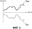
На фиг.2 показаны также две линии, характерные для верхнего значения Shaut и нижнего значения Sbas сигнала для конкретного режима вращения ротора. Figure 2 also shows two lines characteristic of the upper value of S haut and the lower value of S bas signal for a particular mode of rotation of the rotor.
Эти значения определяют заранее определенные пороги сигнала, которые соответствуют «нормальной» работе турбореактивного двигателя, то есть работе турбореактивного двигателя без попадания в него посторонних предметов. Оценку этих значений производят на основании вибрационных данных, снятых на одном или нескольких турбореактивных двигателях, принадлежащих к одному или нескольким разным классам, во время испытаний на земле или в воздухе. Предпочтительно эти значения получают на основании данных, регистрируемых в полете для одного и того же класса турбореактивных двигателей.These values determine the predetermined thresholds of the signal that correspond to the "normal" operation of the turbojet engine, that is, the operation of the turbojet engine without foreign objects entering it. These values are estimated based on vibration data taken on one or more turbojet engines belonging to one or more different classes during tests on the ground or in the air. Preferably, these values are obtained based on data recorded in flight for the same class of turbojet engines.
Как показано на фиг.3, максимальные значения Shaut и минимальные значения Sbas, определяющие пороги, зависят от режима вращения ротора турбореактивного двигателя. На этой фигуре эти значения определены в различных коротких диапазонах режима вращения ротора.As shown in FIG. 3, the maximum values of S haut and the minimum values of S bas defining thresholds depend on the rotation mode of the rotor of the turbojet engine. In this figure, these values are defined in various short ranges of rotor rotation mode.
Во время этапа Е40 способа (фиг.1) амплитуду сигнала, зарегистрированного в скользящем временном окне, постоянно (то есть непрерывно) сравнивают с верхними и нижними значениями, определяющими заранее определенные пороги сигнала для рассматриваемого режима вращения ротора.During step E40 of the method (FIG. 1), the amplitude of a signal recorded in a moving time window is continuously (i.e. continuously) compared with upper and lower values defining predetermined signal thresholds for the rotor rotation mode under consideration.
Этот этап сравнения, который осуществляют на уровне электронного вычислительного устройства EMU, позволяет обнаружить возможное превышение заранее определенных порогов пиком амплитуды сигнала. В случае, показанном на фиг.3, пик амплитуды сигнала, выходящий за пределы Shaut (в области положительных значений) или Sbas (в области отрицательных значения), должен быть немедленно обнаружен.This comparison step, which is carried out at the level of the electronic computing device EMU, makes it possible to detect the possible excess of predetermined thresholds by the peak of the signal amplitude. In the case shown in FIG. 3, a peak in signal amplitude that goes beyond S haut (in the region of positive values) or S bas (in the region of negative values) should be detected immediately.
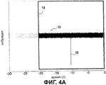
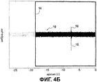
В случае превышения порога пиком амплитуды электронное вычислительное устройство EMU дает команду на сохранение в памяти одновременно временного окна, предшествующего выходу за пределы порога, и окна, следующего сразу за переходом порога. Так, как показано на фиг.4А и 4Б, временное окно 14, центрованное по пику амплитуды (соответственно 16 и 18), сохраняют в памяти (продолжительность этого окна составляет, например, приблизительно 20 секунд).If the threshold is exceeded by the peak amplitude, the electronic computing device EMU instructs to store simultaneously the time window that precedes the threshold and the window immediately after the threshold. So, as shown in figa and 4B, the
На фиг.4А и 4Б показаны два разных типа превышения порога: пик амплитуды на фиг.4А характеризует электронное возмущение сигнала (например, связанное с помехами от других электронных компонентов), тогда как пики амплитуды на фиг.4Б характеризуют попадание предмета в турбореактивный двигатель (постороннего предмета или детали, отделившейся от турбореактивного двигателя).Figs. 4A and 4B show two different types of exceeding the threshold: the amplitude peak in Fig. 4A characterizes the electronic disturbance of the signal (for example, due to interference from other electronic components), while the amplitude peaks in Fig. 4B characterize the penetration of an object into a turbojet engine ( foreign object or part separated from the turbojet engine).
Описанный ниже этап анализа позволяет различать эти два типа событий.The analysis step described below allows you to distinguish between these two types of events.
Можно использовать (альтернативно или один за другим) два метода, чтобы отличить механический удар, которому подвергся ротор, от простого электронного возмущения сигнала (в этом случае говорят также “outlier” для аберрантного наблюдения). Эти методы применяют при помощи вычислительных средств электронного вычислительного устройства EMU.Two methods can be used (alternatively or one after the other) to distinguish the mechanical shock to which the rotor has suffered from a simple electronic signal perturbation (in this case they also say “outlier” for aberrant observation). These methods are applied using the computing means of the electronic computing device EMU.
Один из методов состоит в автоматическом исследовании симметрии пика амплитуды относительно оси симметрии наблюдаемого сигнала. Действительно, различные испытания позволили установить, что механический удар, которому подвергся ротор турбореактивного двигателя, как правило, приводит к, по существу, симметричному пику амплитуды, что далеко не всегда происходит при электронном возмущении сигнала.One of the methods is to automatically study the symmetry of the amplitude peak with respect to the axis of symmetry of the observed signal. Indeed, various tests made it possible to establish that the mechanical shock to which the rotor of a turbojet engine was subjected, as a rule, leads to a substantially symmetric peak in amplitude, which does not always occur with electronic signal perturbation.
Исследование симметрии пика амплитуды может, например, состоять в проверке соблюдения следующего условия:A study of peak amplitude symmetry may, for example, consist in verifying that the following condition is met:

где «М» является максимальным положительным значением, которое принимает пик амплитуды, «m» является минимальным отрицательным значением пика амплитуды, и «с» является параметром, заранее определенным конструктором двигателя.where “M” is the maximum positive value that the amplitude peak takes, “m” is the minimum negative value of the amplitude peak, and “c” is a parameter predetermined by the engine designer.
Если вышеуказанное условие соблюдено, считают, что переход порога пиком амплитуды, вероятно, не связан с электронным возмущением сигнала.If the above condition is met, it is believed that the transition of the threshold with a peak in amplitude is probably not related to the electronic disturbance of the signal.
Разумеется, можно предусмотреть оценку других условий, позволяющих автоматически определить, является пик амплитуды симметричным или нет.Of course, it is possible to provide an assessment of other conditions that can automatically determine whether the amplitude peak is symmetric or not.
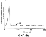
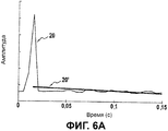
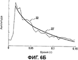
Другой метод, позволяющий отличить механический удар, которому подвергся ротор, от простого электронного возмущения сигнала, состоит в определении наличия ослабления сигнала после пика амплитуды. Действительно, сигнал, характерный для механического удара, которому подвергся ротор, будет всегда содержать ослабление после пика амплитуды, тогда как электронное возмущение сигнала такого ослабления не показывает.Another method that distinguishes the mechanical shock to which the rotor has suffered from a simple electronic signal perturbation is to determine whether the signal is attenuated after the peak amplitude. Indeed, the signal characteristic of the mechanical shock to which the rotor has suffered will always contain attenuation after the amplitude peak, while the electronic perturbation of the signal does not show such attenuation.
Для этого производят оценку моделирования понижения сигнала после пика амплитуды на основании спектрограммы сигнала, зарегистрированной во временном окне (на фигурах не показана). После этого вычисляют среднее значение амплитуд этой спектрограммы в каждый момент, что позволяет получить кривые 20, 22, показанные на фиг.5А и 5Б, соответственно для электронного возмущения сигнала и для механического удара, которому подвергся ротор.To do this, evaluate the simulation of the decrease in the signal after the amplitude peak based on the spectrogram of the signal recorded in the time window (not shown in the figures). After that, calculate the average value of the amplitudes of this spectrogram at each moment, which allows you to get the
Затем анализируют сходство между кривой Х (Х представляет собой кривую 20 или 22) и функцией экспоненциального типа, характеризующей ослабленный удар. Для этого, предположив, что при помощи убывающей экспоненциальной функции типа Y=A.e-t/τ можно произвести аппроксимацию кривой 20, 22, определяют коэффициенты «а» и «b», при которых прямая In(Y)=In(A)+(-1/τ)×t=a+b×t характеризует хорошую линейную аппроксимацию в направлении наименьших квадратов кривой In(X). На Фиг.6А и 6Б прямые 20', 22' соответствуют линейной аппроксимации в направлении наименьших квадратов соответственно для электронного возмущения сигнала и для механического удара, которому подвергся ротор.The similarities between the X curve (X is a
Во время вычисления линейной аппроксимации при помощи метода наименьших квадратов коэффициент определения прямой регрессии является измерением сходства кривой Х с экспоненциальной кривой: минимальный порог на коэффициенте определения позволяет решить, является ли кривая Х достаточной близкой к экспоненциальной кривой, то есть в достаточной ли степени сигнал отображает механический удар.When calculating a linear approximation using the least squares method, the coefficient of determining the direct regression is a measure of the similarity of the curve X with the exponential curve: the minimum threshold on the coefficient of determination allows you to decide whether the curve X is sufficiently close to the exponential curve, that is, whether the signal represents the mechanical hit.
Согласно предпочтительному отличительному признаку изобретения, после определения механического удара, которому подвергся ротор турбореактивного двигателя, способ дополнительно состоит в определении, появился ли на роторе дисбаланс в результате этого удара. Такой дисбаланс может быть связан с частичной или полной потерей одной или нескольких лопаток, столкнувшихся с попавшим внутрь предметом. Речь может также идти об образовании выемок на этих лопатках.According to a preferred feature of the invention, after determining the mechanical shock to which the rotor of the turbojet engine has been subjected, the method further comprises determining whether an imbalance has occurred on the rotor as a result of this shock. Such an imbalance can be associated with a partial or complete loss of one or more shoulder blades that collide with an object that has fallen inside. It can also be about the formation of recesses on these blades.
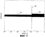
На фиг.7 показан временной сигнал 10, характерный для появления дисбаланса на роторе турбореактивного двигателя вследствие механического удара. Как видно из этой фигуры, форма сигнала 10' после пика амплитуды 18 в результате механического удара по ротору отличается от формы сигнала 10 до пика амплитуды.7 shows a
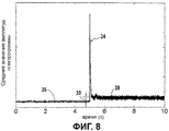
Например, метод автоматического определения появления дисбаланса состоит в выполнении спектрограммы вибрационного сигнала во временном окне, центрованном по пику амплитуды 18. После этого вычисляют среднее значение амплитуд этой спектрограммы в каждый момент, что позволяет получить кривую 24, показанную на фиг.8.For example, the method for automatically detecting the appearance of an imbalance consists in executing a spectrogram of a vibrational signal in a time window centered on the peak of
Среднее значение амплитуды точек кривой 24 (называемое также уровнем среднего значения) вычисляют после и до пика амплитуды 18. Эти средние значения дают две линии 26 и 28, показанные на фиг.8, соответственно для участка кривой до пика амплитуды и для участка кривой после пика амплитуды.The average value of the amplitude of the points of curve 24 (also called the average level) is calculated after and before the peak of
Разность 30 между этими двумя уровнями вычисляют и сравнивают с заранее определенным порогом уровня. Если разность выходит за пределы порога уровня, можно считать, что на роторе турбореактивного двигателя в результате механического удара появился дисбаланс, и эту информацию можно добавить в сообщение обслуживания, передаваемое для предупреждения о наличии повреждений FOD или DOD.The
Как в случае вибрационного порога, порог уровня, используемый для определения появления дисбаланса, оценивают на основании вибрационных данных, снятых на одном или нескольких турбореактивных двигателях, принадлежащих к одному и тому же классу или к нескольким разным классам, во время испытаний, производимых на земле или в полете.As in the case of a vibration threshold, the level threshold used to determine the occurrence of an imbalance is evaluated based on vibration data recorded on one or more turbojet engines belonging to the same class or to several different classes during tests performed on the ground or in flight.
Claims (10)
получают (Е10) сигнал, характерный для вибрационного уровня ротора во время работы турбореактивного двигателя;
получают (Е20) режим вращения ротора во время работы;
сравнивают (Е40) амплитуду сигнала, по меньшей мере, с одним заранее определенным вибрационным порогом в зависимости от режима вращения ротора; и
в случае превышения порога пиком амплитуды анализируют (Е50) сигнал во временном окне, образованном вокруг пика амплитуды, чтобы определить (Е60), является ли явление, ставшее причиной пика амплитуды, механическим ударом, которому подвергся ротор турбореактивного двигателя, или электронным возмущением сигнала.1. A method of controlling a turbojet engine, comprising:
receive (E10) a signal characteristic of the vibrational level of the rotor during operation of the turbojet engine;
receive (E20) the rotor rotation mode during operation;
comparing (E40) the amplitude of the signal with at least one predetermined vibration threshold depending on the mode of rotation of the rotor; and
if the threshold is exceeded by the amplitude peak, analyze (E50) the signal in the time window formed around the amplitude peak to determine (E60) whether the phenomenon that caused the amplitude peak is a mechanical shock to which the rotor of the turbojet engine was subjected, or an electronic signal perturbation.
выполняют спектрограмму сигнала во временном окне;
вычисляют среднее значение амплитуд спектрограммы в каждый момент;
вычисляют разность уровня среднего значения до и после пика амплитуды;
и сравнивают разность уровня с заранее определенным порогом уровня.7. The method according to claim 6, in which the step of determining the occurrence of an imbalance on the rotor is that:
perform a spectrogram of the signal in a time window;
calculate the average value of the amplitudes of the spectrogram at each moment;
calculating the difference in the level of the average value before and after the peak amplitude;
and comparing the level difference with a predetermined level threshold.
Applications Claiming Priority (3)
| Application Number | Priority Date | Filing Date | Title |
|---|---|---|---|
| FR0856855A FR2937079B1 (en) | 2008-10-10 | 2008-10-10 | METHOD AND SYSTEM FOR MONITORING A TURBOREACTOR |
| FR0856855 | 2008-10-10 | ||
| PCT/FR2009/051930 WO2010040966A1 (en) | 2008-10-10 | 2009-10-09 | Method and system for monitoring a turbojet engine |
Publications (2)
| Publication Number | Publication Date |
|---|---|
| RU2011118448A RU2011118448A (en) | 2012-11-20 |
| RU2507403C2 true RU2507403C2 (en) | 2014-02-20 |
Family
ID=40673987
Family Applications (1)
| Application Number | Title | Priority Date | Filing Date |
|---|---|---|---|
| RU2011118448/06A RU2507403C2 (en) | 2008-10-10 | 2009-10-09 | Method and system for turbojet control |
Country Status (9)
| Country | Link |
|---|---|
| US (1) | US8560272B2 (en) |
| EP (1) | EP2344728B1 (en) |
| JP (1) | JP5512685B2 (en) |
| CN (1) | CN102177313B (en) |
| BR (1) | BRPI0919598B1 (en) |
| CA (1) | CA2738893C (en) |
| FR (1) | FR2937079B1 (en) |
| RU (1) | RU2507403C2 (en) |
| WO (1) | WO2010040966A1 (en) |
Families Citing this family (28)
| Publication number | Priority date | Publication date | Assignee | Title |
|---|---|---|---|---|
| FR2952177B1 (en) | 2009-11-04 | 2012-06-01 | Snecma | METHOD FOR DETECTING DAMAGE TO AT LEAST ONE BEARING BEARING OF AN ENGINE |
| FR2956159B1 (en) * | 2010-02-08 | 2012-02-10 | Snecma | METHOD FOR AUTOMATED DETECTION OF INGESTION OF AT LEAST ONE FOREIGN BODY BY A GAS TURBINE ENGINE |
| FR2968038B1 (en) * | 2010-11-26 | 2012-12-28 | Snecma | SYSTEM FOR DETECTING A FUGACEOUS EVENT ON AN AIRCRAFT ENGINE BEARING WHEEL |
| FR2974929B1 (en) * | 2011-05-06 | 2013-06-14 | Snecma | DEVICE FOR MONITORING AN AIRCRAFT ENGINE |
| US9046000B2 (en) | 2011-06-18 | 2015-06-02 | Prime Photonics, Lc | Method for detecting foreign object damage in turbomachinery |
| FR2977341B1 (en) | 2011-06-30 | 2013-06-28 | Eurocopter France | METHOD FOR MONITORING AN AIRCRAFT BY VIBRATION ACQUISITIONS |
| EP2594912A1 (en) * | 2011-11-21 | 2013-05-22 | Eurocopter Deutschland GmbH | Detection system for detection of damages on rotating components of aircraft and method of operating such a detection system |
| FR2986269B1 (en) | 2012-01-30 | 2015-08-07 | Snecma | SYSTEM FOR DETECTING AN IMPACT ON AN AIRCRAFT ENGINE BEARING WHEEL |
| FR2988130B1 (en) * | 2012-03-13 | 2014-05-09 | Snecma | DEFECT DETECTION SYSTEM ON AN AIRCRAFT ENGINE BEARING WHEEL |
| FR2988444B1 (en) | 2012-03-20 | 2016-01-15 | Snecma | DETECTION OF A FOREIGN OBJECT IMPACT AT THE ENTRANCE OF AN AIRCRAFT ENGINE |
| US9080925B2 (en) * | 2012-06-13 | 2015-07-14 | The Boeing Company | Engine vibration and engine trim balance test system, apparatus and method |
| GB201302815D0 (en) * | 2013-02-19 | 2013-04-03 | Rolls Royce Plc | Determining the deterioration of a gas turbine engine in use |
| FR3009021B1 (en) * | 2013-07-23 | 2015-08-21 | Snecma | METHOD OF ESTIMATING A CURVE OF A RELEVANT POINT FOR ANOMALY DETECTION OF AN ENGINE AND A DATA PROCESSING SYSTEM FOR ITS IMPLEMENTATION |
| US10048116B2 (en) | 2013-08-23 | 2018-08-14 | Siemens Energy, Inc. | Detection system for identifying blockages in guide vanes of a turbine engine |
| US20150184533A1 (en) * | 2013-12-26 | 2015-07-02 | General Electric Company | Methods and systems to monitor health of rotor blades |
| US9657588B2 (en) * | 2013-12-26 | 2017-05-23 | General Electric Company | Methods and systems to monitor health of rotor blades |
| CN103913177B (en) * | 2014-03-28 | 2016-06-15 | 吉林大学 | A kind of rotary-wing flight state monitoring apparatus |
| US10908014B2 (en) * | 2014-08-21 | 2021-02-02 | Baker Hughes, A Ge Company, Llc | Detecting rotor anomalies during transient speed operations |
| DE102014220317A1 (en) * | 2014-10-07 | 2016-04-07 | Rolls-Royce Deutschland Ltd & Co Kg | Aircraft gas turbine engine with shock absorbing element for fan blade loss |
| GB201611524D0 (en) | 2016-07-01 | 2016-08-17 | Rolls Royce Plc | Rotor blade damage |
| DE102017200964A1 (en) | 2017-01-20 | 2018-07-26 | Rolls-Royce Deutschland Ltd & Co Kg | Measuring device and measuring method for detecting mixed friction events and / or stick-slip events |
| US10836255B2 (en) * | 2017-12-15 | 2020-11-17 | Caterpillar Inc. | On-board monitoring and event detection system for a machine with rotating components |
| CN110821578B (en) * | 2018-08-14 | 2022-04-15 | 中国航发商用航空发动机有限责任公司 | Mass flight event identification method and identification system |
| DE102018131948B4 (en) * | 2018-12-12 | 2023-10-26 | Deutsches Zentrum für Luft- und Raumfahrt e.V. | Method and device for detecting an impact event and a vehicle for this purpose |
| US11035246B2 (en) | 2019-01-14 | 2021-06-15 | Pratt & Whitney Canada Corp. | Method and system for detecting fan blade structural failure |
| JP7379241B2 (en) | 2020-03-25 | 2023-11-14 | 三菱重工業株式会社 | Rotating machine diagnostic monitoring device and method |
| US11698287B2 (en) * | 2020-08-31 | 2023-07-11 | Rolls-Royce Deutschland Ltd & Co Kg | System and method for detecting vibrations in rotating machinery |
| CN116398257B (en) * | 2023-04-12 | 2024-05-03 | 中国航发湖南动力机械研究所 | Aviation turboshaft engine rotor clamping stagnation diagnosis method and system |
Citations (10)
| Publication number | Priority date | Publication date | Assignee | Title |
|---|---|---|---|---|
| US4437163A (en) * | 1980-03-31 | 1984-03-13 | Hitachi, Ltd. | Method and apparatus for symptom diagnosis by monitoring vibration of shaft of rotary machine |
| US4453407A (en) * | 1980-04-17 | 1984-06-12 | Hitachi, Ltd. | Vibration diagnosis method and apparatus for rotary machines |
| RU2017080C1 (en) * | 1991-05-20 | 1994-07-30 | Санкт-Петербургский опытный завод "Прибор" | Device for testing vibration of gas-turbine engine |
| WO1997043729A1 (en) * | 1996-05-14 | 1997-11-20 | Csi Technology, Inc. | Vibration data analysis based on time waveform parameters |
| WO2001075272A2 (en) * | 2000-04-04 | 2001-10-11 | Swantech, L.L.C. | Turbine engine foreign object damage detection system |
| US6768938B2 (en) * | 2001-11-16 | 2004-07-27 | Goodrich Pump & Engine Control Systems, Inc. | Vibration monitoring system for gas turbine engines |
| US20050199064A1 (en) * | 2004-02-10 | 2005-09-15 | Samsung Electronics Co., Ltd. | Apparatus, method, and medium for detecting and discriminating impact sound |
| US20070250245A1 (en) * | 2006-04-21 | 2007-10-25 | Van Der Merwe Gert J | Method and apparatus for operating a gas turbine engine |
| RU70005U1 (en) * | 2007-06-19 | 2008-01-10 | Андрей Павлович Ушаков | DEVICE FOR DIAGNOSTIC OF TECHNICAL CONDITION OF PARTS, UNITS AND DRIVE UNITS OF A GAS TURBINE ENGINE |
| RU2320969C2 (en) * | 2002-05-28 | 2008-03-27 | Снекма Моторс | Method and system of finding faults in flying vehicle engine rotor and flying vehicle engine |
Family Cites Families (4)
| Publication number | Priority date | Publication date | Assignee | Title |
|---|---|---|---|---|
| AT381890B (en) * | 1983-01-13 | 1986-12-10 | Mogilevskij Otdel Fiz T I | ROTATION CHISEL |
| US6366862B1 (en) * | 2000-04-19 | 2002-04-02 | National Instruments Corporation | System and method for analyzing signals generated by rotating machines |
| JP4117208B2 (en) * | 2003-03-31 | 2008-07-16 | 九州電力株式会社 | Method for determining damage form of steam turbine by AE signal |
| US7809513B2 (en) * | 2007-04-16 | 2010-10-05 | Acellent Technologies, Inc. | Environmental change compensation in a structural health monitoring system |
-
2008
- 2008-10-10 FR FR0856855A patent/FR2937079B1/en active Active
-
2009
- 2009-10-09 CN CN200980139910.5A patent/CN102177313B/en active Active
- 2009-10-09 RU RU2011118448/06A patent/RU2507403C2/en active
- 2009-10-09 US US13/120,663 patent/US8560272B2/en active Active
- 2009-10-09 EP EP09756001.5A patent/EP2344728B1/en active Active
- 2009-10-09 CA CA2738893A patent/CA2738893C/en active Active
- 2009-10-09 JP JP2011530534A patent/JP5512685B2/en active Active
- 2009-10-09 BR BRPI0919598A patent/BRPI0919598B1/en active IP Right Grant
- 2009-10-09 WO PCT/FR2009/051930 patent/WO2010040966A1/en active Application Filing
Patent Citations (10)
| Publication number | Priority date | Publication date | Assignee | Title |
|---|---|---|---|---|
| US4437163A (en) * | 1980-03-31 | 1984-03-13 | Hitachi, Ltd. | Method and apparatus for symptom diagnosis by monitoring vibration of shaft of rotary machine |
| US4453407A (en) * | 1980-04-17 | 1984-06-12 | Hitachi, Ltd. | Vibration diagnosis method and apparatus for rotary machines |
| RU2017080C1 (en) * | 1991-05-20 | 1994-07-30 | Санкт-Петербургский опытный завод "Прибор" | Device for testing vibration of gas-turbine engine |
| WO1997043729A1 (en) * | 1996-05-14 | 1997-11-20 | Csi Technology, Inc. | Vibration data analysis based on time waveform parameters |
| WO2001075272A2 (en) * | 2000-04-04 | 2001-10-11 | Swantech, L.L.C. | Turbine engine foreign object damage detection system |
| US6768938B2 (en) * | 2001-11-16 | 2004-07-27 | Goodrich Pump & Engine Control Systems, Inc. | Vibration monitoring system for gas turbine engines |
| RU2320969C2 (en) * | 2002-05-28 | 2008-03-27 | Снекма Моторс | Method and system of finding faults in flying vehicle engine rotor and flying vehicle engine |
| US20050199064A1 (en) * | 2004-02-10 | 2005-09-15 | Samsung Electronics Co., Ltd. | Apparatus, method, and medium for detecting and discriminating impact sound |
| US20070250245A1 (en) * | 2006-04-21 | 2007-10-25 | Van Der Merwe Gert J | Method and apparatus for operating a gas turbine engine |
| RU70005U1 (en) * | 2007-06-19 | 2008-01-10 | Андрей Павлович Ушаков | DEVICE FOR DIAGNOSTIC OF TECHNICAL CONDITION OF PARTS, UNITS AND DRIVE UNITS OF A GAS TURBINE ENGINE |
Also Published As
| Publication number | Publication date |
|---|---|
| CN102177313B (en) | 2014-04-16 |
| EP2344728A1 (en) | 2011-07-20 |
| CA2738893A1 (en) | 2010-04-15 |
| BRPI0919598B1 (en) | 2020-05-05 |
| CA2738893C (en) | 2017-11-21 |
| EP2344728B1 (en) | 2016-02-10 |
| WO2010040966A1 (en) | 2010-04-15 |
| JP5512685B2 (en) | 2014-06-04 |
| FR2937079B1 (en) | 2011-08-26 |
| RU2011118448A (en) | 2012-11-20 |
| US8560272B2 (en) | 2013-10-15 |
| FR2937079A1 (en) | 2010-04-16 |
| JP2012505341A (en) | 2012-03-01 |
| US20110178772A1 (en) | 2011-07-21 |
| BRPI0919598A2 (en) | 2015-12-08 |
| CN102177313A (en) | 2011-09-07 |
Similar Documents
| Publication | Publication Date | Title |
|---|---|---|
| RU2507403C2 (en) | Method and system for turbojet control | |
| US8528317B2 (en) | Method and system for detecting the ingestion of an object by an aircraft turbine engine during a mission | |
| US8942886B2 (en) | System for detecting an impact on an aircraft engine impeller wheel | |
| JP6203811B2 (en) | Detect and track damage to aero engine fans or impact of foreign objects on them | |
| EP0022671B1 (en) | Method and apparatus for determining the mass of an impacting object | |
| US20130268154A1 (en) | Detection system for detection of damages on rotating components of components of aircraft and method of operating such a detection system | |
| US8538729B2 (en) | Method and system of wind turbine condition monitoring | |
| US8958946B2 (en) | System for detecting defects on an aircraft engine impeller wheel | |
| US20210063276A1 (en) | Method and device for monitoring a bearing equipping a rotary device | |
| EP2399104A1 (en) | Method and apparatus for monitoring and analyzing vibrations in rotary machines | |
| US20090198455A1 (en) | Automated crack detection system and method for vehicle closure | |
| CN111400961A (en) | Wind generating set blade fault judgment method and device | |
| RU2551252C2 (en) | Method of automated detection of ingress of, at least, one foreign matter into gas-turbine engine | |
| CN116800504A (en) | Dynamic authentication method and device for terminal physical fingerprint extraction and illegal access | |
| RU2644986C1 (en) | Method of impact measurement on fastening structure of aircraft on-board equipment at presence of vibration and impact loads in measured process | |
| CN111319787B (en) | Helicopter moving part vibration monitoring data validity evaluation method | |
| KR20170081355A (en) | Drive system for helicopter vibration diagnosis method | |
| JP2006216039A (en) | System for implementing condition monitoring activity | |
| EP4343301A1 (en) | Method for identifying periodic shocks in a structure, wind turbine generator and a wind farm adapted for performing the method | |
| CN111275336A (en) | Equipment state evaluation method | |
| CN111868497A (en) | Method and system for detecting damage to a moving blade of an aircraft | |
| CN110821578B (en) | Mass flight event identification method and identification system | |
| RU2773588C1 (en) | Method for spectral assessment of the occurrence of the pre-surge condition of aircraft gas turbine engines | |
| CN114858270A (en) | Low-frequency vibration detection system and method for last-stage blade of nuclear turbine |
Legal Events
| Date | Code | Title | Description |
|---|---|---|---|
| PD4A | Correction of name of patent owner |