RU2315537C2 - Storage container system - Google Patents
Storage container system Download PDFInfo
- Publication number
- RU2315537C2 RU2315537C2 RU2005102069/12A RU2005102069A RU2315537C2 RU 2315537 C2 RU2315537 C2 RU 2315537C2 RU 2005102069/12 A RU2005102069/12 A RU 2005102069/12A RU 2005102069 A RU2005102069 A RU 2005102069A RU 2315537 C2 RU2315537 C2 RU 2315537C2
- Authority
- RU
- Russia
- Prior art keywords
- groove
- wall
- container
- partition
- bracket
- Prior art date
Links
Images

Classifications
-
- F—MECHANICAL ENGINEERING; LIGHTING; HEATING; WEAPONS; BLASTING
- F25—REFRIGERATION OR COOLING; COMBINED HEATING AND REFRIGERATION SYSTEMS; HEAT PUMP SYSTEMS; MANUFACTURE OR STORAGE OF ICE; LIQUEFACTION SOLIDIFICATION OF GASES
- F25D—REFRIGERATORS; COLD ROOMS; ICE-BOXES; COOLING OR FREEZING APPARATUS NOT OTHERWISE PROVIDED FOR
- F25D25/00—Charging, supporting, and discharging the articles to be cooled
- F25D25/02—Charging, supporting, and discharging the articles to be cooled by shelves
- F25D25/024—Slidable shelves
- F25D25/025—Drawers
-
- A—HUMAN NECESSITIES
- A47—FURNITURE; DOMESTIC ARTICLES OR APPLIANCES; COFFEE MILLS; SPICE MILLS; SUCTION CLEANERS IN GENERAL
- A47B—TABLES; DESKS; OFFICE FURNITURE; CABINETS; DRAWERS; GENERAL DETAILS OF FURNITURE
- A47B88/00—Drawers for tables, cabinets or like furniture; Guides for drawers
- A47B88/90—Constructional details of drawers
-
- F—MECHANICAL ENGINEERING; LIGHTING; HEATING; WEAPONS; BLASTING
- F25—REFRIGERATION OR COOLING; COMBINED HEATING AND REFRIGERATION SYSTEMS; HEAT PUMP SYSTEMS; MANUFACTURE OR STORAGE OF ICE; LIQUEFACTION SOLIDIFICATION OF GASES
- F25D—REFRIGERATORS; COLD ROOMS; ICE-BOXES; COOLING OR FREEZING APPARATUS NOT OTHERWISE PROVIDED FOR
- F25D2331/00—Details or arrangements of other cooling or freezing apparatus not provided for in other groups of this subclass
- F25D2331/80—Type of cooled receptacles
- F25D2331/803—Bottles
-
- F—MECHANICAL ENGINEERING; LIGHTING; HEATING; WEAPONS; BLASTING
- F25—REFRIGERATION OR COOLING; COMBINED HEATING AND REFRIGERATION SYSTEMS; HEAT PUMP SYSTEMS; MANUFACTURE OR STORAGE OF ICE; LIQUEFACTION SOLIDIFICATION OF GASES
- F25D—REFRIGERATORS; COLD ROOMS; ICE-BOXES; COOLING OR FREEZING APPARATUS NOT OTHERWISE PROVIDED FOR
- F25D2400/00—General features of, or devices for refrigerators, cold rooms, ice-boxes, or for cooling or freezing apparatus not covered by any other subclass
- F25D2400/08—Refrigerator tables
-
- F—MECHANICAL ENGINEERING; LIGHTING; HEATING; WEAPONS; BLASTING
- F25—REFRIGERATION OR COOLING; COMBINED HEATING AND REFRIGERATION SYSTEMS; HEAT PUMP SYSTEMS; MANUFACTURE OR STORAGE OF ICE; LIQUEFACTION SOLIDIFICATION OF GASES
- F25D—REFRIGERATORS; COLD ROOMS; ICE-BOXES; COOLING OR FREEZING APPARATUS NOT OTHERWISE PROVIDED FOR
- F25D25/00—Charging, supporting, and discharging the articles to be cooled
- F25D25/02—Charging, supporting, and discharging the articles to be cooled by shelves
- F25D25/024—Slidable shelves
Landscapes
- Engineering & Computer Science (AREA)
- General Engineering & Computer Science (AREA)
- Combustion & Propulsion (AREA)
- Physics & Mathematics (AREA)
- Mechanical Engineering (AREA)
- Thermal Sciences (AREA)
- Chemical & Material Sciences (AREA)
- Refrigerator Housings (AREA)
- Details Of Rigid Or Semi-Rigid Containers (AREA)
- Valve Device For Special Equipments (AREA)
- Vehicle Body Suspensions (AREA)
- Memory System Of A Hierarchy Structure (AREA)
- Devices That Are Associated With Refrigeration Equipment (AREA)
Abstract
Description
Область техникиTechnical field
Предлагаемое изобретение относится к системе для хранения с контейнером и разделяющим элементом, который насаживается на верхний край стенки контейнера. Такой разделяющий элемент может в свою очередь представлять собой контейнер меньшего размера для подвешивания в вышеупомянутом контейнере, или он может образовывать перегородку для разделения контейнера на различные камеры.The present invention relates to a storage system with a container and a separating element, which is mounted on the upper edge of the container wall. Such a separating element may, in turn, be a smaller container for hanging in the aforementioned container, or it may form a partition to divide the container into different chambers.
Уровень техникиState of the art
Устройство для хранения последнего типа известно из патентного документа ЕР-0611535 А1. Разделительный элемент этого устройства состоит из скобы для насаживания на стенку контейнера и отходящей от скобы перегородки. Скоба имеет открытый снизу паз такого размера, что надетая на стенку контейнера скоба упруго зажмет ее. Дно паза образовано двумя планками с упорами, которые при собранном состоянии разделительного элемента опираются на верхний край стенки, образуя между собой щель, переходящую в канал, тянущийся вдоль скобы. Щель и канал можно рассматривать как отходящий от дна первого паза второй паз. Назначение канала не указывается.A device for storing the latter type is known from patent document EP-0611535 A1. The separation element of this device consists of a bracket for mounting on the container wall and a partition extending from the bracket. The bracket has a groove open at the bottom of such a size that the bracket mounted on the container wall will clamp it elastically. The bottom of the groove is formed by two planks with stops, which, when the separation element is assembled, rest on the upper edge of the wall, forming a gap between them, passing into a channel that extends along the bracket. The slot and channel can be considered as a second groove extending from the bottom of the first groove. The purpose of the channel is not indicated.
Недостаток известного из ЕР-0611535 разделительного элемента состоит в том, что его можно закрепить только на стенке с точно заданной толщиной. Однако с точки зрения экономии веса и материала может оказаться желательным предусматривать в контейнере стенки разной толщины. В этом случае известный разделительный элемент можно устанавливать только на тех стенках контейнера, толщина которых рассчитана на размер паза разделительного элемента. Это существенно ограничивает гибкость применения разделительного элемента.A disadvantage of the separation element known from EP-0611535 is that it can only be mounted on a wall with a precisely defined thickness. However, from the point of view of saving weight and material, it may be desirable to provide walls of different thicknesses in the container. In this case, the known separation element can only be installed on those container walls whose thickness is designed for the size of the groove of the separation element. This significantly limits the flexibility of the separation element.
Раскрытие изобретенияDisclosure of invention
Задача предлагаемого изобретения состоит в том, чтобы создать устройство или систему для хранения с контейнером и закрепляемым на стенках контейнера разделительным элементом, в каковой системе разделительный элемент можно устанавливать на стенках различной толщины.The objective of the invention is to create a device or system for storage with a container and a separation element fixed to the walls of the container, in which system the separation element can be installed on walls of various thicknesses.
Эта задача решается системой для хранения с признаками по пункту 1 формулы изобретения. Она позволяет крепить разделительный элемент на двух типах стенок различной толщины, причем более узкая стенка может быть вставлена сквозь первый паз во второй паз, тогда как при насаживании разделительного элемента на стенку большей толщины стенка упирается в дно первого паза.This problem is solved by the storage system with features according to paragraph 1 of the claims. It allows you to fasten the separation element on two types of walls of different thicknesses, and a narrower wall can be inserted through the first groove into the second groove, while when pushing the separating element on the wall of greater thickness, the wall abuts the bottom of the first groove.
Чтобы обеспечить прочную фиксацию разделительного элемента на стенках обоих типов, желательно, чтобы первый и второй паз имели общую плоскую боковую грань, к которой стенка, на которую насаживается разделительный элемент, могла бы так же плоско прилегать.In order to ensure a firm fixation of the separation element on both types of walls, it is desirable that the first and second groove have a common flat side face, to which the wall on which the separation element is mounted could also lie flat.
Так как глубина вхождения толстой стенки в первый паз меньше глубины вхождения тонкой стенки, которая проходит через оба паза, то для прочной фиксации разделительного элемента на первой стенке желательно, чтобы в ней была предусмотрена выемка, и скоба в области первого паза имела выступ, который входил бы в выемку.Since the depth of entry of a thick wall into the first groove is less than the depth of entry of a thin wall that passes through both grooves, it is desirable that a recess is provided for it to be firmly fixed to the first wall, and the bracket in the region of the first groove has a protrusion that would be in the recess.
Для улучшения фиксации разделительного элемента на второй стенке можно предусмотреть, чтобы второй паз был отделен от первого паза ребром, которое при установке разделительного элемента на второй стенке входило бы в предусмотренную на ней канавку.To improve the fixation of the separation element on the second wall, it can be provided that the second groove is separated from the first groove by a rib, which, when the separation element was installed on the second wall, would fit into the groove provided on it.
Для увеличения жесткости разделительного элемента ребро может быть соединено с дном второго паза, по меньшей мере, одной перемычкой.To increase the rigidity of the spacer element, the rib can be connected to the bottom of the second groove with at least one jumper.
В принципе, на дне второго паза может быть предусмотрен третий паз, предназначенный для насаживания на еще более тонкую стенку.In principle, at the bottom of the second groove, a third groove may be provided for mounting on an even thinner wall.
Разделительный элемент может быть выполнен в виде перегородки или в виде еще одного ящика, предназначенного для хранения в нем предметов.The dividing element may be made in the form of a partition or in the form of another box designed to store items in it.
Контейнер, на котором крепится разделительный элемент, используется предпочтительно в качестве выдвижного ящика для холодильного аппарата. Однако и сам корпус холодильного аппарата может рассматриваться как такой контейнер, причем в этом случае стенками, на которые насаживается разделительный элемент, предпочтительно являются стенки расположенных внутри корпуса контейнеров, таких как выдвижные ящики, дверные полки и т.д.The container on which the separation element is mounted is preferably used as a drawer for the refrigeration apparatus. However, the refrigerator case itself can be considered as such a container, and in this case the walls on which the separation element is mounted are preferably the walls of containers located inside the case, such as drawers, door shelves, etc.
Краткий перечень чертежейBrief List of Drawings
Другие признаки и преимущества изобретения вытекают из нижеследующего описания примеров реализации со ссылками на прилагаемые чертежи, на которых изображены:Other features and advantages of the invention result from the following description of exemplary embodiments with reference to the accompanying drawings, in which:
фиг.1 - вид спереди холодильного аппарата с выдвижными ящиками, на стенках которых установлены разделительные элементы согласно изобретению;figure 1 is a front view of a refrigerator with drawers, on the walls of which are installed dividing elements according to the invention;
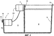
фиг.2 - разрез выдвижного ящика, снабженного разделительными элементами; иfigure 2 - section of a drawer equipped with dividing elements; and
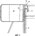
фиг.3, 4 - соответственно увеличенные детали по фиг.2.figure 3, 4 are respectively enlarged details of figure 2.
Осуществление изобретенияThe implementation of the invention
На фиг.1 изображен спереди корпус 1 холодильного аппарата со снятой дверью, оснащенного несколькими выдвижными ящиками 2, 3. Верхние выдвижные ящики 2 имеют форму мелких чаш; нижний выдвижной ящик 3 разделен на отделение 4 для овощей, стенки которого имеют одинаковую по всему периметру большую высоту, и отделение 5 меньшей высоты для бутылок. Перегородка 6 проходит на двух разных уровнях по высоте поперек внутренней полости холодильного аппарата.Figure 1 shows the front case 1 of the refrigerator with the door removed, equipped with several drawers 2, 3. The upper drawers 2 are in the form of small bowls; the lower drawer 3 is divided into a
На фиг.2 показан разрез через нижний выдвижной ящик 3 в плоскости поперек направления выдвижения ящика с двумя смонтированными на стенках выдвижного ящика 3 разделительными элементами 7. Отделение 4 для овощей и отделение 5 для бутылок разделены перегородкой 8, которая по всей высоте имеет практически одинаковую толщину. Наружные стенки 9, 10 выдвижного ящика 3 уширены по верхнему краю буртиком 11, что придает им жесткость. Надетые на перегородку 8 и на наружную стенку 10 идентичные разделительные элементы 7 представляют собой неразъемные детали, состоящие из скобы 14 и проходящей до середины высоты отделения 5 для бутылок перегородки 23. Размеры отделения 5 для бутылок выбраны так, что в нем можно установить два ряда бутылок обычных размеров; при этом перегородки служат соответственно для защиты бутылок в одном из этих рядов от опрокидывания.Figure 2 shows a section through the lower drawer 3 in a plane transverse to the direction of the drawer extension with two
На фиг.3 показано в увеличенном виде крепление разделительного элемента 7 на наружной стенке 10. Наружный край буртика 11 продолжен повернутой вниз полоской 12, в нижней части которой образована выемка 13. Скоба 14 разделительного элемента имеет открытый снизу наружный паз 15. Наружный паз 15 ограничен сбоку с одной стороны приформованной к перегородке 23 частью скобы 14, а с другой стороны - наружной частью 16 скобы 14, которая примыкает заподлицо к верхнему краю корпуса разделительного элемента. Дно наружного паза 15 образовано отходящим от наружной части 16 горизонтальным ребром 17, которое ложится на буртик 11. Направленный внутрь паза 15 выступ 18 на конце наружной части 16 входит в выемку 13. Буртик 11 незначительно шире, чем дно паза 15 при ненапряженном, несмонтированном состоянии скобы, так что смонтированный на наружной стенке 10 разделительный элемент плотно держится на ней.Figure 3 shows in an enlarged view the fastening of the separating
На дне наружного паза 15 между приформованной к перегородке 23 частью скобы 14 и ребром 17 имеется щель, которая образует вход во внутренний паз 19. Ширина внутреннего паза 19 и, соответственно, щели соответствует толщине перегородки 8, так что разделительный ящик зажимается на ней, как показано на фиг.4. Для повышения жесткости наружной части 16 между выступом 18 и дном 21 внутреннего паза 19 предусмотрена одна или несколько перемычек 20. Неглубокая канавка 22 тянется вдоль перегородки 8 на таком расстоянии от верхнего края, чтобы ребро 17 заскакивало в канавку 22, когда верхний край доходит до дна 21 внутреннего паза 19.At the bottom of the
В другом варианте исполнения разделительного элемента 1 перегородка 23 может быть заменена ящиком или сходным контейнером.In another embodiment of the separation element 1, the
На фиг.4 канавка 22 показана только на одной стороне перегородки 8, однако очевидно, что ее можно было бы выполнить на обеих сторонах перегородки 8, что позволило бы устанавливать разделительный элемент 7 по желанию на отделении 5 для бутылок или на отделении 4 для овощей. Кроме того, разделительный элемент 7 можно монтировать также на любом из выдвижных ящиков 2, если они имеют стенку, сечение которой совпадает с сечением наружной стенки 10 или перегородки 8, и высоту, достаточную для установки разделительного элемента. Соответственно, такой же разделительный элемент 7 можно было бы устанавливать на (не показаны) дверных полках.In figure 4, the groove 22 is shown only on one side of the
Вместо двух расположенных друг над другом пазов 15, 19, как описано выше, скоба 14 может быть оснащена также тремя или более пазами, расположенными друг над другом, для монтажа на соответствующем количестве типов стенок различной толщины.Instead of two
Claims (10)
Applications Claiming Priority (2)
| Application Number | Priority Date | Filing Date | Title |
|---|---|---|---|
| DE10236215.7 | 2002-08-07 | ||
| DE10236215A DE10236215B3 (en) | 2002-08-07 | 2002-08-07 | Storage arrangement |
Publications (2)
| Publication Number | Publication Date |
|---|---|
| RU2005102069A RU2005102069A (en) | 2005-10-10 |
| RU2315537C2 true RU2315537C2 (en) | 2008-01-27 |
Family
ID=29719527
Family Applications (1)
| Application Number | Title | Priority Date | Filing Date |
|---|---|---|---|
| RU2005102069/12A RU2315537C2 (en) | 2002-08-07 | 2003-07-24 | Storage container system |
Country Status (9)
| Country | Link |
|---|---|
| EP (1) | EP1528878B1 (en) |
| CN (1) | CN100518581C (en) |
| AT (1) | ATE315349T1 (en) |
| AU (1) | AU2003250169A1 (en) |
| DE (2) | DE10236215B3 (en) |
| ES (1) | ES2256788T3 (en) |
| PL (1) | PL201412B1 (en) |
| RU (1) | RU2315537C2 (en) |
| WO (1) | WO2004014190A1 (en) |
Cited By (9)
| Publication number | Priority date | Publication date | Assignee | Title |
|---|---|---|---|---|
| RU2557723C2 (en) * | 2010-02-05 | 2015-07-27 | Пауль Хеттих Гмбх Унд Ко. Кг | Drawer with separation system |
| WO2021113799A1 (en) * | 2019-12-06 | 2021-06-10 | Dooli Products, LLC | Furniture anti-tipping mechanisms |
| USD927229S1 (en) | 2020-02-25 | 2021-08-10 | Dooli Products, LLC | Curved dresser |
| USD927230S1 (en) | 2020-02-25 | 2021-08-10 | Dooli Products, LLC | Dresser with straight front |
| USD927899S1 (en) | 2020-02-25 | 2021-08-17 | Dooli Products, LLC | Partly tapered dresser |
| US11103067B2 (en) | 2019-12-06 | 2021-08-31 | Dooli Products, LLC | Furniture with anti-tipping features |
| USD932216S1 (en) | 2019-12-06 | 2021-10-05 | Dooli Products, LLC | Tapered dresser |
| US11266243B2 (en) | 2019-12-06 | 2022-03-08 | Dooli Products, LLC | Furniture having anti-tipping construction |
| US11684157B1 (en) | 2022-12-13 | 2023-06-27 | Thoughtful Furniture Company, Llc | Furniture with anti-tipping support hinge |
Families Citing this family (3)
| Publication number | Priority date | Publication date | Assignee | Title |
|---|---|---|---|---|
| DE20313431U1 (en) * | 2003-08-29 | 2003-10-23 | Bsh Bosch Siemens Hausgeraete | Insert container for a refrigerator |
| DE102007021572A1 (en) * | 2007-05-08 | 2008-11-13 | BSH Bosch und Siemens Hausgeräte GmbH | Rail for a suspension system |
| DE102013225089A1 (en) * | 2013-12-06 | 2015-06-11 | BSH Hausgeräte GmbH | Household refrigerating appliance with an interior in which a carrier is slidably disposed, on which a container is positioned |
Family Cites Families (4)
| Publication number | Priority date | Publication date | Assignee | Title |
|---|---|---|---|---|
| DE3200142A1 (en) * | 1982-01-05 | 1983-07-14 | Heimo Mag.pharm. Bad Ischl Hrovat | DRAWER FOR THE ORIGINAL STORAGE OF SMALL PARTS |
| GB9004841D0 (en) * | 1990-03-03 | 1990-04-25 | Sarap International Limited | Divider/follower for a drawer |
| DE9302215U1 (en) * | 1993-02-16 | 1993-05-27 | Bosch-Siemens Hausgeraete Gmbh, 8000 Muenchen, De | |
| DE20007960U1 (en) * | 2000-01-14 | 2000-08-24 | Blum Gmbh Julius | Divider for dividing drawers |
-
2002
- 2002-08-07 DE DE10236215A patent/DE10236215B3/en not_active Expired - Fee Related
-
2003
- 2003-07-24 ES ES03784072T patent/ES2256788T3/en not_active Expired - Lifetime
- 2003-07-24 CN CNB038191431A patent/CN100518581C/en not_active Expired - Fee Related
- 2003-07-24 DE DE50302205T patent/DE50302205D1/en not_active Expired - Lifetime
- 2003-07-24 WO PCT/EP2003/008172 patent/WO2004014190A1/en not_active Application Discontinuation
- 2003-07-24 PL PL373344A patent/PL201412B1/en not_active IP Right Cessation
- 2003-07-24 RU RU2005102069/12A patent/RU2315537C2/en not_active IP Right Cessation
- 2003-07-24 AT AT03784072T patent/ATE315349T1/en not_active IP Right Cessation
- 2003-07-24 EP EP03784072A patent/EP1528878B1/en not_active Expired - Lifetime
- 2003-07-24 AU AU2003250169A patent/AU2003250169A1/en not_active Abandoned
Cited By (10)
| Publication number | Priority date | Publication date | Assignee | Title |
|---|---|---|---|---|
| RU2557723C2 (en) * | 2010-02-05 | 2015-07-27 | Пауль Хеттих Гмбх Унд Ко. Кг | Drawer with separation system |
| WO2021113799A1 (en) * | 2019-12-06 | 2021-06-10 | Dooli Products, LLC | Furniture anti-tipping mechanisms |
| US11103067B2 (en) | 2019-12-06 | 2021-08-31 | Dooli Products, LLC | Furniture with anti-tipping features |
| USD932216S1 (en) | 2019-12-06 | 2021-10-05 | Dooli Products, LLC | Tapered dresser |
| US11234520B2 (en) | 2019-12-06 | 2022-02-01 | Dooli Products, LLC | Furniture with lashing mechanism |
| US11266243B2 (en) | 2019-12-06 | 2022-03-08 | Dooli Products, LLC | Furniture having anti-tipping construction |
| USD927229S1 (en) | 2020-02-25 | 2021-08-10 | Dooli Products, LLC | Curved dresser |
| USD927230S1 (en) | 2020-02-25 | 2021-08-10 | Dooli Products, LLC | Dresser with straight front |
| USD927899S1 (en) | 2020-02-25 | 2021-08-17 | Dooli Products, LLC | Partly tapered dresser |
| US11684157B1 (en) | 2022-12-13 | 2023-06-27 | Thoughtful Furniture Company, Llc | Furniture with anti-tipping support hinge |
Also Published As
| Publication number | Publication date |
|---|---|
| EP1528878B1 (en) | 2006-01-11 |
| RU2005102069A (en) | 2005-10-10 |
| CN100518581C (en) | 2009-07-29 |
| AU2003250169A1 (en) | 2004-02-25 |
| DE10236215B3 (en) | 2004-01-08 |
| ES2256788T3 (en) | 2006-07-16 |
| PL201412B1 (en) | 2009-04-30 |
| PL373344A1 (en) | 2005-08-22 |
| WO2004014190A1 (en) | 2004-02-19 |
| CN1674811A (en) | 2005-09-28 |
| DE50302205D1 (en) | 2006-04-06 |
| EP1528878A1 (en) | 2005-05-11 |
| ATE315349T1 (en) | 2006-02-15 |
Similar Documents
| Publication | Publication Date | Title |
|---|---|---|
| RU2315537C2 (en) | Storage container system | |
| RU2004126479A (en) | WALL-MOUNTED STORAGE DEVICE | |
| US4826265A (en) | Shelving system for musical instrument storage | |
| US5655673A (en) | Large spice jar rack | |
| US9631860B2 (en) | Chest freezer | |
| KR20150094049A (en) | Refrigerator | |
| RU2008111571A (en) | CARRIER FOR COOLED ITEMS | |
| US5042398A (en) | Refrigerator shelf support method and apparatus | |
| US20060279188A1 (en) | Door compartment for a refrigerator | |
| US4724643A (en) | Retainer clip with resilient pad | |
| RU2004123970A (en) | END COVER FOR GLASS PLATE AND REFRIGERATOR SHELF WITH SUCH COVER | |
| US7703865B2 (en) | Storage compartment for a refrigeration device | |
| CN219889941U (en) | Storage assembly and refrigerator | |
| KR200394010Y1 (en) | The structure of seperate-panel of a kim-chi refrigerator's vegetable room | |
| US8215064B2 (en) | Shower vanity | |
| EP0547740A2 (en) | Holder for a cassette tape | |
| KR0138571Y1 (en) | Shelf Support of Freezer Showcase | |
| KR101030498B1 (en) | A shelf for refrigerators | |
| RU2408826C2 (en) | Refrigerating unit with storage device | |
| KR200192821Y1 (en) | A corner cabinet for bathroom | |
| JPS6240303Y2 (en) | ||
| KR200180238Y1 (en) | Shelf for refrigerator | |
| KR200239614Y1 (en) | Refrigerator with door guard | |
| KR101461957B1 (en) | Refrigerator | |
| KR200184962Y1 (en) | Megazine loading stand |
Legal Events
| Date | Code | Title | Description |
|---|---|---|---|
| MM4A | The patent is invalid due to non-payment of fees |
Effective date: 20130725 |