RU2314931C2 - Protection element, provided with macro-structure - Google Patents
Protection element, provided with macro-structure Download PDFInfo
- Publication number
- RU2314931C2 RU2314931C2 RU2004132232/12A RU2004132232A RU2314931C2 RU 2314931 C2 RU2314931 C2 RU 2314931C2 RU 2004132232/12 A RU2004132232/12 A RU 2004132232/12A RU 2004132232 A RU2004132232 A RU 2004132232A RU 2314931 C2 RU2314931 C2 RU 2314931C2
- Authority
- RU
- Russia
- Prior art keywords
- macrostructure
- pattern
- element according
- layer
- function
- Prior art date
Links
Images
Classifications
-
- B—PERFORMING OPERATIONS; TRANSPORTING
- B42—BOOKBINDING; ALBUMS; FILES; SPECIAL PRINTED MATTER
- B42D—BOOKS; BOOK COVERS; LOOSE LEAVES; PRINTED MATTER CHARACTERISED BY IDENTIFICATION OR SECURITY FEATURES; PRINTED MATTER OF SPECIAL FORMAT OR STYLE NOT OTHERWISE PROVIDED FOR; DEVICES FOR USE THEREWITH AND NOT OTHERWISE PROVIDED FOR; MOVABLE-STRIP WRITING OR READING APPARATUS
- B42D25/00—Information-bearing cards or sheet-like structures characterised by identification or security features; Manufacture thereof
- B42D25/30—Identification or security features, e.g. for preventing forgery
- B42D25/328—Diffraction gratings; Holograms
-
- B—PERFORMING OPERATIONS; TRANSPORTING
- B42—BOOKBINDING; ALBUMS; FILES; SPECIAL PRINTED MATTER
- B42D—BOOKS; BOOK COVERS; LOOSE LEAVES; PRINTED MATTER CHARACTERISED BY IDENTIFICATION OR SECURITY FEATURES; PRINTED MATTER OF SPECIAL FORMAT OR STYLE NOT OTHERWISE PROVIDED FOR; DEVICES FOR USE THEREWITH AND NOT OTHERWISE PROVIDED FOR; MOVABLE-STRIP WRITING OR READING APPARATUS
- B42D15/00—Printed matter of special format or style not otherwise provided for
- B42D15/0033—Owner certificates, insurance policies, guarantees
-
- B—PERFORMING OPERATIONS; TRANSPORTING
- B42—BOOKBINDING; ALBUMS; FILES; SPECIAL PRINTED MATTER
- B42D—BOOKS; BOOK COVERS; LOOSE LEAVES; PRINTED MATTER CHARACTERISED BY IDENTIFICATION OR SECURITY FEATURES; PRINTED MATTER OF SPECIAL FORMAT OR STYLE NOT OTHERWISE PROVIDED FOR; DEVICES FOR USE THEREWITH AND NOT OTHERWISE PROVIDED FOR; MOVABLE-STRIP WRITING OR READING APPARATUS
- B42D15/00—Printed matter of special format or style not otherwise provided for
- B42D15/0053—Forms specially designed for commercial use, e.g. bills, receipts, offer or order sheets, coupons
-
- B—PERFORMING OPERATIONS; TRANSPORTING
- B42—BOOKBINDING; ALBUMS; FILES; SPECIAL PRINTED MATTER
- B42D—BOOKS; BOOK COVERS; LOOSE LEAVES; PRINTED MATTER CHARACTERISED BY IDENTIFICATION OR SECURITY FEATURES; PRINTED MATTER OF SPECIAL FORMAT OR STYLE NOT OTHERWISE PROVIDED FOR; DEVICES FOR USE THEREWITH AND NOT OTHERWISE PROVIDED FOR; MOVABLE-STRIP WRITING OR READING APPARATUS
- B42D15/00—Printed matter of special format or style not otherwise provided for
- B42D15/0073—Printed matter of special format or style not otherwise provided for characterised by shape or material of the sheets
Landscapes
- Credit Cards Or The Like (AREA)
- Burglar Alarm Systems (AREA)
- Road Signs Or Road Markings (AREA)
- Diffracting Gratings Or Hologram Optical Elements (AREA)
- Laminated Bodies (AREA)
- Materials For Medical Uses (AREA)
- Silicon Compounds (AREA)
Abstract
Description
Изобретение относится к элементу защиты, снабженному макроструктурой, который характеризуется совокупностью признаков, согласно ограничительной части п.1 формулы.The invention relates to a security element equipped with a macrostructure, which is characterized by a combination of features, according to the restrictive part of claim 1 of the formula.
Такие элементы защиты выполняют в виде тонкой многослойной композиции из пластика, причем внутри многослойной композиции содержатся, по меньшей мере, модифицирующие свет рельефные структуры и плоские зеркальные поверхности. Вырезанные из тонкой многослойной композиции элементы защиты наклеивают на предметы для удостоверения из подлинности.Such security elements are in the form of a thin multilayer composition made of plastic, and at least light-modifying relief structures and flat mirror surfaces are contained within the multilayer composition. Carved from a thin multilayer composition, security elements are glued onto objects for authentication.
Состав тонкой многослойной композиции и применяемые для нее материалы описаны, например, в документе US 4856857. Из GB 2129739 А известно также нанесение тонкой многослойной композиции на предмет с помощью пленки-основы.The composition of the thin multilayer composition and the materials used for it are described, for example, in US Pat. No. 4,856,857. From GB 2,129,739 A, it is also known to apply a thin multilayer composition to an object using a base film.
Структура описанного выше рода известна из ЕР 0429782 В1. Наклеенный на документ элемент защиты имеет при этом известный, например, из ЕР 0105099 А1 или ЕР 0375833 А1, оптически изменяющийся поверхностный узор из расположенных наподобие мозаики участков поверхности с известными дифракционными структурами и другими модифицирующими свет рельефными структурами. Для того чтобы фальшивый документ для имитации кажущейся подлинности нельзя было без заметных следов снабдить подделанным, вырезанным из подлинного документа или отделенным от подлинного документа элементом защиты, в элементе защиты и в граничащих с ним частях документа тиснением выполняют защитные профили. Тиснение защитных профилей мешает обнаружению оптически изменяющегося поверхностного узора. В частности, положение штампа для тиснения изменяется на элементе защиты от одного экземпляра документа к другому.The structure of the genus described above is known from EP 0 429 782 B1. The security element affixed to the document has, for example, a well-known, for example, from EP 0105099 A1 or EP 0375833 A1, optically changing surface pattern from mosaic-like surface areas with known diffractive structures and other light-modifying relief structures. In order for a fake document to simulate apparent authenticity to be impossible to provide without noticeable signs a security element forged, cut from an original document or separated from the original document, protective profiles are made in the security element and in the parts of the document adjacent to it by embossing. The embossing of the protective profiles prevents the detection of an optically variable surface pattern. In particular, the position of the stamp for stamping changes on the security element from one copy of the document to another.
Известно также, что ранее у особенно важных документов подлинность документа удостоверялась сургучной печатью. Сургучная печать имеет сложно выполненный рельефный рисунок.It is also known that earlier, in especially important documents, the authenticity of a document was certified by a wax seal. The wax seal has a complicated relief pattern.
В основе изобретения лежит задача создания недорогого элемента защиты с новым оптическим эффектом, состоящего из тонкой многослойной композиции и закрепляемого на предмете, подлинность которого удостоверяется.The basis of the invention is the task of creating an inexpensive security element with a new optical effect, consisting of a thin multilayer composition and fixed on an object, the authenticity of which is verified.
Указанная задача решается согласно изобретению посредством элемента защиты в виде многослойной композиции, лежащей в образуемой осями (х; у) координат базовой плоскости, при этом элемент защиты включает слой формованного полимерного материала и защитный слой из полимерного материала, внутри которых в виде узора выполнены структуры, вызывающие оптические эффекты, которые на участках поверхности узора выполнены в слое формованного материала и образуют отражающую граничную поверхность, расположенную между прозрачным слоем формованного материала и защитным слоем многослойной композиции, при этом, по меньшей мере, один участок граничной поверхности размером более 0,4 мм в качестве структуры вызывающей оптический эффект снабжен, по меньшей мере, одной отформованной макроструктурой (М) с удаленными друг от друга, по меньшей мере, на 0,1 мм соседними предельными значениями, при этом макроструктура (М) в зависимости от координат (х; у), описываемая, по меньшей мере, кусочно-непрерывной и дифференцируемой функцией, по меньшей мере, на отдельных участках искривлена, и не является периодической треугольной или прямоугольной функцией.This problem is solved according to the invention by means of a security element in the form of a multilayer composition lying in the coordinates of the base plane formed by the axes (x; y), the security element comprising a layer of molded polymeric material and a protective layer of polymeric material, inside of which structures are made in the form of a pattern, causing optical effects, which on the surface areas of the pattern are made in the layer of the molded material and form a reflective boundary surface located between the transparent layer of the molded the material and the protective layer of the multilayer composition, at least one section of the boundary surface of a size of more than 0.4 mm as the structure causing the optical effect is equipped with at least one molded macrostructure (M) with at least remote from each other at least 0.1 mm by neighboring limit values, while the macrostructure (M) depending on the coordinates (x; y), described by at least a piecewise continuous and differentiable function, at least in some sections is curved, and not lane iodic triangular or rectangular function.
Предпочтительные выполнения изобретения приведены в зависимых пунктах формулы.Preferred embodiments of the invention are given in the dependent claims.
Примеры выполнения изобретения более подробно поясняются ниже и изображены на чертеже, где показаны:Examples of the invention are explained in more detail below and shown in the drawing, which shows:
на фиг.1: элемент защиты на документе;figure 1: security element on the document;
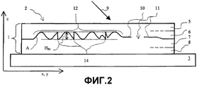
на фиг.2: поперечное сечение многослойной композиции;figure 2: cross section of a multilayer composition;
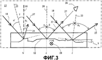
на фиг.3: отражение от макроструктуры;figure 3: reflection from the macrostructure;
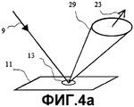
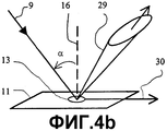
на фиг.4: рассеяние на матовых структурах;figure 4: scattering on opaque structures;
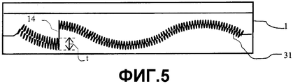
на фиг.5: дополнительное наложение макроструктуры на дифракционную решетку;figure 5: additional superposition of the macrostructure on the diffraction grating;
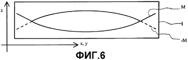
на фиг.6: две макроструктуры элемента защиты в сечении;Fig.6: two macrostructures of the security element in cross section;
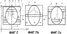
на фиг.7: элемент защиты под разными углами наклона.7: security element at different angles of inclination.
На фиг.1 поз.1 обозначает многослойную композицию, поз.2 - элемент защиты и поз.3 - документ. Элемент 2 защиты содержит в многослойной композиции 1 макроструктуру М, расположенную в зоне узора 4. Элемент 2 защиты расположен в образуемой осями (х, у) координат, воображаемой базовой плоскости. Макроструктура М является однозначной, кусочно-непрерывной и дифференцируемой функцией М(х, у) координат х, у. Функция М(х, у) описывает криволинейную, по меньшей мере, на отдельных участках поверхность, причем на отдельных участках справедливо соотношение ΔМ(х, у)≠0. Макроструктура М является трехмерной поверхностью, причем х, у - являются координатами точки Р(х, у) на поверхности макроструктуры М. Расстояние z(х, у) точки Р(х, у) от базовой плоскости измерено параллельно оси z координат, перпендикулярной изображению на фиг.1. Узор 4 в одном возможном выполнении окружен поверхностным узором 38, c содержащим известные из ЕР 0375833 А1, модифицирующие свет структуры, например плоскую зеркальную поверхность, дифрагирующую свет, микроскопически мелкие решетчатые структуры, матовые структуры и другие структуры. В частности, в одном выполнении поверхность узора 4 выполнена в виде сетки по фиг.1 из документа ЕР 0375833 А1, причем каждый элемент сетки разделен, по меньшей мере, на два поля. В одном из полей отформована структура в соответствии с частью функции М(х, у), а в другом отформованы, например, мозаичные элементы поверхностного узора 38. В другом выполнении на узоре 4 расположены узкие линейные элементы и/или иные мозаичные элементы произвольной формы поверхностного узора 38. Предпочтительно линейные и мозаичные элементы имеют в одном направлении размер 0,05-1 мм. Элемент 2 защиты в другом выполнении является прозрачным в одной краевой зоне вне узора 4.In figure 1, pos. 1 denotes a multilayer composition, pos. 2 - a security element and pos. 3 - a document. The
На фиг.2 изображено поперечное сечение наклеенной на документ 3 многослойной композиции 1. Многослойная композиция 1 состоит из нескольких слоев различных, последовательно нанесенных на пленку-основу (не показана) слоев из полимерных материалов и включает в себя в указанной последовательности обычно покровный 5, отформованный 6, защитный 7 и клеевой 8 слои. По меньшей мере, покровный 5 и отформованный 6 слои выполнены прозрачными для падающего света. Сквозь покровный 5 и отформованный 6 слои виден узор 4.Figure 2 shows a cross section pasted onto a
В случае если защитный 7 и клеевой 8 слои также выполнены прозрачными, через прозрачные места 10 видны размещенные на поверхности подложки 3 характерные признаки (не показаны). Прозрачные места 10 находятся, например, внутри узора 4 и/или в окружающей узор 4 краевой зоне элемента 2 защиты. Краевая зона в одном выполнении совершенно прозрачная, а в другом - прозрачная только в заданных местах 10. Пленка-основа может в одном выполнении образовывать покровный слой 5, а в другом служит для прикрепления тонкой многослойной композиции 1 к подложке 3, после чего ее удаляют с многослойной композиции 1, как это описано в GB 2129739 А.If the protective 7 and adhesive 8 layers are also made transparent, characteristic features (not shown) located on the surface of the
Общей поверхностью соприкосновения между отформованным 6 и защитным 7 слоями является граничная поверхность 11. В отформованном слое 6 выполнены структуры 12 вызывающие оптический эффект макроструктуры М узора 4 (фиг.1), с высотой НSt структуры. Поскольку защитный слой 7 заполняет впадины структур 12 вызывающих оптический эффект, функция М(х, у) описывает граничную поверхность 11. Для достижения высокой эффективности оптического действия структур 12 граничная поверхность 11, которая отделяет отформованный слой 6 от защитного слоя 7 и выполнена в виде отражающего слоя, может быть образована металлическим покрытием, преимущественно из элементов приведенных в таблице 5 в документе US 4856857, в частности алюминия, серебра, золота, меди, хрома, тантала и т.д. Электрическая проводимость металлического покрытия обеспечивает высокую отражающую способность граничной поверхности 11 по отношению к падающему видимому свету 9. Однако вместо металлического покрытия пригодны также один или несколько слоев одного из известных прозрачных неорганических диэлектриков, приведенных, например, в таблицах 1 и 4 в документе US 4856857, или отражающий слой выполнен в виде многослойного интерференционного слоя, например двухслойной комбинации металл-диэлектрик, металл-диэлектрик-металл и т.д. Отражающий слой в одном выполнении структурирован, т.е. покрывает граничную поверхность 11 лишь частично и оставляет ее свободной в заданных прозрачных местах 10.The common contact surface between the molded 6 and protective 7 layers is the
Многослойную композицию 1 изготавливают в виде полимерного ламината в виде длинного пленочного полотна с множеством расположенных рядом друг с другом копий узора 4. Из пленочного полотна элементы 2 защиты, например, вырезают и соединяют с документом 3 посредством клеевого слоя 8. Под документы 3 подпадают банкноты, кредитные карточки, удостоверения или иные важные или ценные предметы.The multilayer composition 1 is made in the form of a polymer laminate in the form of a long film web with many copies of the
Макроструктура М(х, у) составлена для простых узоров 4 из одного или нескольких участков 13 поверхности (фиг. 1), причем макроструктуры М(х, у) описаны на участках 13 поверхности математическими функциями, например М(х, у)=0,5·(х2+у2) К, М(х, у)=а·{1+sin(2πFx·x)·sin(2πFy·y)}, М(х, у)=a·x1,5+b·x, М(х, у)=a·{1+sin(2πFy·y)}, причем Fx и Fy обозначают пространственную частоту F периодической макроструктуры М(х,у) в направлении соответственно оси х и у координат. В другом выполнении узора 4 макроструктура М(х, у) периодически составлена из заданного фрагмента другой математической функции и имеет один или несколько периодов на участке 13 поверхности. Пространственные частоты F имеют значение самое большее 20 линий на миллиметр и лежат преимущественно ниже значения 5 линий на миллиметр. Размер участка 13 поверхности, по меньшей мере, в одном направлении, составляет более 0,4 мм, с тем чтобы детали узора 4 можно было различить невооруженным глазом.The macrostructure M (x, y) is composed for
В другом выполнении один или несколько участков 13 поверхности образуют рельефный рисунок в качестве узора 4, причем граничная поверхность 11 вместо простых математических функций следует за макроструктурой М поверхности рельефного рисунка. Примеры узора 4 можно найти на геммах или тисненых изображениях, таких как печати, монеты, медали и т.д. Макроструктура М поверхности рельефного рисунка является кусочно-непрерывной и дифференцируемой и искривлена на участках поверхности.In another embodiment, one or
В других выполнениях макроструктура М имитирует другой видимый трехмерный характер поверхности, например текстуру почти периодических переплетений или тканей, множества относительно просто структурированных тел в равномерном или неравномерном расположении и т.д. Перечисление возможных макроструктур М неполное, поскольку множество макроструктур М являются кусочно-непрерывными и дифференцируемыми и, по меньшей мере, на участках поверхности справедливо ΔМ(х, у)≠0.In other embodiments, the macrostructure M imitates another visible three-dimensional nature of the surface, for example, the texture of almost periodic weaves or fabrics, many relatively simple structured bodies in a uniform or uneven arrangement, etc. The enumeration of the possible macrostructures of M is incomplete, since the set of macrostructures of M are piecewise continuous and differentiable and, at least on the surface, ΔM (x, y) ≠ 0.
Многослойная композиция 1 не должна слишком сильно выделяться на документе 3. С одной стороны, документы 3 иначе плохо штабелировались бы, а, с другой стороны, толстая многослойная композиция 1 представляла бы собой поверхность приложения усилия для отделения многослойной композиции 1 от документа 3. Толщина многослойной композиции колеблется в зависимости от заданного применения и составляет обычно 3-100 мкм. Отформованный слой 6 является лишь частью многослойной композиции 1, так что допустимая, с точки зрения структуры многослойной композиции 1, высота НSt структуры, выполненной в отформованном слое 6 макроструктуры М, ограничена значениями менее 40 мкм. Кроме того, при выполнении макроструктуры М возрастают технические трудности по мере увеличения высоты структуры, так что предпочтительные значения высоты структуры НSt составляют менее 5 мкм. Профильная высота h макроструктуры М является разностью между значением z=М(х, у) в точке Р(х, у) от опорной плоскости и значением z0=М(х0,у0) в точке Р(х0,у0) минимального расстояния z0 от базовой плоскости, то есть профильной высотой h=z(x, y)-z0.The multilayer composition 1 should not stand out too much on the
На фиг.2 не в масштабе в качестве примера изображена граничная поверхность 11 в виде выполненной в отформованном слое 6 структуры А со структурами 12, вызывающими оптический эффект, которые имеют рельефную высоту hR. Параметры структуры А описываются функцией А(х; у) координат х, у. Высота многослойной композиции 1 определяется по оси z координат. Поскольку в процессе формования макроструктура М может превышать заданное значение структурной высоты НSt структуры, в каждой точке Р(х, у) узора 4 профильная высота h макроструктуры М должна быть ограничена заданным подъемом Н структуры А. Если профильная высота h макроструктуры М превышает значение Н, то предпочтительно из профильной высоты h вычитают подъем Н до тех пор, пока рельефная высота hR отформованной структуры А не будет меньше подъема Н, т.е. hR = профильная высота h по modulo подъем Н. Таким образом, макроструктуры М с высокими значениями профильной высоты h должны быть отформованы также в многослойной композиции 1 толщиной несколько микрон, причем в отформованной структуре А возникают образовавшиеся по техническим причинам неровности 14.Figure 2 does not illustrate, by way of example, the
Неровности 14 отформованной структуры, определяемой как А(х; у)={М(х; у)+С(х; у)} modulo Н - С(х; у), не являются поэтому предельными значениями функции М(х; у). Функция С(х; у) ограничена при этом по величине диапазоном значений, например половиной значения высоты НSt структуры. Точно так же в определенных выполнениях узора 4 по техническим причинам значения подъема Н могут локально отличаться. Значение Н подъема отформованной структуры А ограничено менее чем 30 мкм и лежит преимущественно в диапазоне Н = 0,5-4 мкм. В одном выполнении дифракционной структуры S(х; у) локально изменяющееся значение Н подъема определяется тем, что расстояние между двумя следующими друг за другом неровностями Pn не превышает заданного значения 40-300 мкм.The irregularities of the 14 molded structure, defined as A (x; y) = {M (x; y) + C (x; y)} modulo H - C (x; y), are therefore not limit values of the function M (x; y) ) The function C (x; y) is limited in value by a range of values, for example, half the value of the height H St of the structure. Similarly, in certain embodiments of
Отформованная структура А между двумя соседними неровностями 14 идентична макроструктуре М. Поэтому отформованная структура А создает, за исключением отбрасывания тени, в хорошем приближении тот же оптический эффект, что и оригинальная макроструктура М. Освещенный узор 4 ведет себя, следовательно, при рассмотрении с наклоном и/или с вращением многослойной композиции 1 в базовой плоскости, как рельефный рисунок или как описанная макроструктурой М трехмерная поверхность, хотя многослойная композиция имеет толщину всего несколько микрон.The molded structure A between two
На фиг.3 показано, как параллельно направленный, падающий на граничную поверхность 11 (фиг.1), снабженную структурой А свет 9 (фиг.2), отражается структурой 12, создающей оптический эффект, и заданным образом отклоняется. В качестве отражающего слоя использован, например, слой алюминия толщиной около 30 нм. Преломление падающего света 9 и отраженного света на границах многослойной композиции 1 для простоты на фиг.3 не показано и в нижеследующих расчетах не учитывается. Падающий свет 9 падает в плоскости 15 падения, содержащей нормаль 16 к базовой плоскости или к поверхности многослойной композиции 1, на структуру 12 многослойной композиции 1. Параллельные лучи 17, 18, 19 падающего света 9 попадают на элементы поверхности структуры А, например в местах а, b, с. Каждый из элементов поверхности имеет локальный наклон γ и нормаль 20, 21, 22 к поверхности в плоскости 15 падения, определяемые составляющей в градусах М(х, у). В первом элементе поверхности в месте а, имеющем локальный наклон γ=0о, первый освещающий луч 17 образует с первой нормалью 20 к поверхности угол α падения, а отраженный при попадании на первый элемент поверхности свет 9 отражается в виде первого луча 23 симметрично нормали 20 к поверхности под углом α=θ. У второго элемента поверхности в месте b локальный наклон γ≠0о. Нормаль 16 и вторая нормаль 21 к поверхности образуют угол γ>0о. Угол падения второго освещающего луча 18 у второго элемента поверхности составляет α'=α-γ, и в соответствии с этим второй отраженный луч 24 образует с нормалью 16 угол θ1=α-2γ. Точно так же третий отраженный луч 24 в соответствии с локальным наклоном γ<0° в месте с отклоняется под углом θ2=α-2γ=α+2|γ|, поскольку угол α'' падения третьего луча 19 к третьей нормали 22 к поверхности на локальный угол γ наклона больше угла падения к нормали 16. Наблюдатель 26, который смотрит в направлении 27 взгляда, лежащем, например, в плоскости 15 падения, воспринимает своим невооруженным глазом отраженный свет лучей 23, 24, 25 только тогда, когда вследствие поворота элемента 2 защиты (фиг.1) или многослойной композиции 1 вокруг оси 28, лежащей в опорной плоскости и ориентированной перпендикулярно плоскости 15 падения, отраженные под разными углами θ, θ1, θ2 к нормали 16 лучи 23, 24, 25, совпадают с направлением 27 взгляда. Под определенным углом поворота наблюдатель 26 различает с высокой поверхностной яркостью элементы поверхности макроструктуры М, имеющие в плоскости 15 падения или в параллельных плоскости 15 падения плоскостях одинаковый локальный наклон γ. Хотя граничная поверхность 11 сама по себе гладкая, другие элементы поверхности макроструктуры М могут также рассеивать немного света параллельно направлению 27 взгляда и представляться наблюдателю 26 в соответствии с локальным наклоном по-разному оттененными. Наблюдатель 26 воспринимает объемное изображение, хотя отформованная структура А имеет в высоту самое большее несколько микрон. За счет наложения макроструктуры М на матовую структуру это рассеивающее действие может быть усилено и контролированно использовано для оформления признака 2 защиты.Figure 3 shows how parallel to the incident on the boundary surface 11 (figure 1), equipped with a structure A light 9 (figure 2), is reflected by the
На фиг.4а, 4b показана разная для падающего света рассеивающая способность участка 13 поверхности элемента 2 защиты 9. Матовые структуры имеют микроскопически мелкую стохастическую структуру на граничной поверхности 11 и описаны рельефным профилем R - функцией координат х, у. Матовые структуры рассеивают, как показано на фиг.4а, параллельно падающий свет 9 в виде конуса 29 рассеяния с заданным рассеивающей способностью матовой структуры углом раскрытия и с направлением отраженного света 23 в качестве оси конуса. Интенсивность рассеянного света наибольшая, например, на оси конуса и уменьшается по мере увеличения расстояния от оси конуса, причем отклоненный в направлении образующих конуса рассеяния свет еще различим наблюдателем. Сечение конуса 29 рассеяния перпендикулярно оси конуса при вертикальном падении света является вращательно-симметричным у матовой структуры, названной в этом случае «изотропной». Если же, как показано на фиг.4b, сечение конуса 29 рассеяния в предпочтительном направлении 30 обжато, т.е. эллиптически деформировано, причем короткая главная ось эллипса ориентирована параллельно предпочтительному направлению 30, то матовая структура называется в этом случае «анизотропной». Сечение конуса 29 рассеяния как у «изотропной» матовой структуры, так и у «анизотропной», расположенной параллельно базовой плоскости, заметно искажается в направлении параллельно плоскости 15 падения (фиг.3), если угол α падения к нормали 16 больше 30°.Figures 4a and 4b show the scattering power of the
Матовые структуры имеют в микроскопическом масштабе мелкие рельефные структурные элементы (не показаны), которые определяют рассеивающую способность и могут быть описаны только статистическими параметрами, например среднее арифметическое отклонение профиля Rа, длина lc корреляции и т.д., причем значения среднего арифметического отклонения профиля Rа лежат в диапазоне от 200 нм до 5 мкм с предпочтительными значениями от 150 нм до 1,5 мкм. Длины lc корреляции имеют, по меньшей мере, в одном направлении значения от 300 нм до 300 мкм, преимущественно от 500 нм до 100 мкм. У «анизотропных» матовых структур рельефные структурные элементы ориентированы параллельно предпочтительному направлению 30. «Изотропные» матовые структуры имеют независимые от направления статистические параметры и потому не имеют предпочтительного направления 30.Matte structures have microscopic small relief structural elements (not shown) that determine the scattering power and can only be described by statistical parameters, for example, the arithmetic mean deviation of the profile R a , the correlation length l c , etc., and the arithmetic mean deviation profile R a lie in the range from 200 nm to 5 μm with preferred values from 150 nm to 1.5 μm. The correlation lengths l c have at least one direction values from 300 nm to 300 μm, preferably from 500 nm to 100 μm. In “anisotropic” opaque structures, embossed structural elements are oriented parallel to the
В другом выполнении отражающий слой состоит из цветного металла, или покровный слой 5 (фиг.2) окрашен и прозрачен. Особенно эффективным является использование одного из многослойных интерференционных слоев на граничной поверхности 11, поскольку за счет выпуклостей макроструктуры М интерференционный слой в направлении 27 взгляда имеет разную толщину и представляется в локально разных, зависимых от угла 28 поворота цветах. В качестве примера интерференционный слой включает в себя слой TiO2 толщиной 100-150 нм между прозрачным металлическим слоем из алюминия толщиной 5 нм и матовым металлическим слоем из алюминия толщиной 50 нм, причем прозрачный металлический слой обращен к слою 6 из формованного материала.In another embodiment, the reflective layer consists of non-ferrous metal, or the coating layer 5 (FIG. 2) is colored and transparent. Especially effective is the use of one of the multilayer interference layers on the
На фиг.5 в виде сечения многослойной композиции 1 изображено другое выполнение макроструктуры М. На макроструктуру М, по меньшей мере, на одном участке 13 поверхности (фиг.4а) дополнительно наложена субмикроскопическая дифракционная решетка 31. Дифракционная решетка 31 имеет рельефный профиль R периодической функции от координат х и у (фиг.2) и постоянный профиль. Глубина t профиля дифракционной решетки 31 имеет значение 0,05-5 мкм, причем предпочтительные значения составляют 0,6±0,5 мкм. Пространственная частота f дифракционной решетки 31 составляет 2400 линий на миллиметр, отсюда и обозначение «субмикроскопическая». Субмикроскопическая дифракционная решетка 31 дифрагирует падающий свет 9 (фиг.4а) только в нулевой порядок дифракции, т.е. в направлении луча 23 (фиг.3) отраженного света, в зависимой от пространственной частоты f области видимого спектра. Отформованная структура А = (макроструктура М modulo значение Н подъема) + рельефный профиль R создает, тем самым, эффект цветного выпуклого зеркала. Если глубина t профиля дифракционной решетки 31 достаточно мала (<50 нм), то имеет место гладкая, ахроматически отражающая падающий свет 9 зеркальная поверхность в качестве граничной поверхности 11 (фиг.2). За пределами неровностей 14 макроструктура М постепенно изменяется по сравнению с субмикроскопической дифракционной решеткой, которая простирается по макроструктуре М на участке 13 поверхности с постоянной высотой профиля.Figure 5 shows in a cross-sectional view of the multilayer composition 1 another embodiment of the macrostructure M. The
На фиг.6 изображено сечение многослойной композиции 1 с другим выполнением элемента 2 защиты (фиг.2). Элемент 2 защиты включает в себя, по меньшей мере, два участка 13 поверхности (фиг.4а), расположенные на фиг.6 друг за другом. Макроструктура М на переднем участке 13 поверхности описывается, например, математической функцией М(у)=0,5·у2·К, а макроструктура М на заднем участке 13 поверхности определяется функцией М(у)= - 0,5·у2·К. Находящиеся на заднем участке 13 поверхности части макроструктуры М(у)= - 0,5·у2·К закрыты макроструктурой М(у)=0,5·у2·К расположенной на переднем участке 13 поверхности и потому обозначены на фиг.6 штриховой линией.Figure 6 shows a cross section of a multilayer composition 1 with another embodiment of the protection element 2 (figure 2). The
В общем виде узор 4 (фиг.1) в элементе 2 защиты по фиг.7а-7с содержит овальный первый участок 31 поверхности с изображенной на фиг.6 макроструктурой М(у)=0,5·у2·К, тогда как на граничащих с первым участком 31 поверхности втором 32 и третьем 33 участках поверхности отформована приданная заднему участку 13 поверхности (фиг.4а) макроструктура М(у)= - 0,5·у2·К. Постоянная К является величиной кривизны макроструктуры М. Градиенты макроструктуры М, grad(М), на участках 31, 32, 33 поверхности ориентированы, в основном, параллельно плоскости y/z. Преимущественно направления градиента образуют с плоскостью y/z соответственно угол φ=0° и 180°. Ось z координат перпендикулярна плоскости изображения на фиг.7. При этом допустимы отклонения угла φ в диапазоне δφ = ±30о до предпочтительного значения, с тем чтобы в этом диапазоне рассматривать градиент как, в основном, параллельный плоскости y/z.In general terms, pattern 4 (FIG. 1) in the
При освещении элемента 2 защиты параллельным падающим светом 9 (фиг.4а) узко ограниченные полоски 34 участков 31, 32, 33 поверхности узора 4 отбрасывают отраженный свет с высокой поверхностной яркостью в направлении 27 взгляда наблюдателя 26 (фиг.3). Полоски 34 ориентированы перпендикулярно градиентам. Для простоты градиенты и перпендикулярные им полоски 34 параллельны. Чем меньше кривизна К, тем выше скорость движения полосок 34 на одну угловую единицу в направлении проецированных на опорную плоскость составляющих 35, 36 градиентов при вращении вокруг оси 28. Ширина полосок 34 зависит от локальной кривизны К и характера граничной поверхности 11 (фиг.2) используемой структуры А. При равной величине кривизны полоски 34 отражающих граничных поверхностей 11 являются более узкими по сравнению с полосками граничных поверхностей 11 с микроскопически мелкой матовой структурой. Вне полосок 34 участки 31, 32, 33 поверхности видны в сером тоне. Разрез по полосе 37 изображен на фиг.6.When illuminating the
На фиг.7b элемент 2 защиты изображен после вращения вокруг оси 28 поворота под определенным углом, под которым полоски 34 на узоре 4 (фиг.3) на втором 32 и третьем 33 и на первом 31 участках поверхности лежат по одной линии параллельно оси 28 поворота. Этот заданный угол поворота определяется выбором и позиционированием макроструктур М. В одном выполнении элемента 2 защиты на окружающем узор 4 поверхностном узоре заданный знак можно видеть только тогда, когда полоски 34 занимают заданное положение, например положение на фиг.7b, т.е. когда наблюдатель 26 (фиг.3) рассматривает элемент 2 защиты в определенных заданным углом поворота условиях рассмотрения.In Fig. 7b, the
На фиг.7с после дальнейшего вращения вокруг оси 28 поворота полоски 34 на узоре (фиг.1) снова расходятся, как это обозначено на фиг.7с стрелками (не показаны).In Fig. 7c, after further rotation around the axis of
Само собой, для узора 4 с целью ориентации элемента 2 защиты в другом выполнении достаточно смежного расположения первого 31 и одного из обоих других участков 32, 33 поверхности.Of course, for the
Не отклоняясь от идеи изобретения, описанные выше выполнения узора 4 можно комбинировать между собой, соответственно формованные макроструктуры М дополнительно накладывать на выпуклые зеркальные поверхности и матовые структуры, а также использовать все названные выполнения граничной поверхности 11 (фиг.6).Without deviating from the idea of the invention, the above described embodiments of the
Claims (12)
Applications Claiming Priority (2)
| Application Number | Priority Date | Filing Date | Title |
|---|---|---|---|
| DE10216561.0 | 2002-04-05 | ||
| DE10216561A DE10216561B4 (en) | 2002-04-05 | 2002-04-05 | Security element with macrostructures |
Publications (2)
| Publication Number | Publication Date |
|---|---|
| RU2004132232A RU2004132232A (en) | 2005-04-20 |
| RU2314931C2 true RU2314931C2 (en) | 2008-01-20 |
Family
ID=28458824
Family Applications (1)
| Application Number | Title | Priority Date | Filing Date |
|---|---|---|---|
| RU2004132232/12A RU2314931C2 (en) | 2002-04-05 | 2003-04-03 | Protection element, provided with macro-structure |
Country Status (15)
| Country | Link |
|---|---|
| US (1) | US7002746B2 (en) |
| EP (1) | EP1492678B1 (en) |
| JP (1) | JP2005528634A (en) |
| KR (1) | KR20040106311A (en) |
| CN (1) | CN1646328B (en) |
| AT (1) | ATE421926T1 (en) |
| AU (1) | AU2003224034A1 (en) |
| DE (2) | DE10216561B4 (en) |
| DK (1) | DK1492678T3 (en) |
| ES (1) | ES2321079T3 (en) |
| PL (1) | PL204059B1 (en) |
| PT (1) | PT1492678E (en) |
| RU (1) | RU2314931C2 (en) |
| SI (1) | SI1492678T1 (en) |
| WO (1) | WO2003084766A2 (en) |
Cited By (1)
| Publication number | Priority date | Publication date | Assignee | Title |
|---|---|---|---|---|
| RU174679U1 (en) * | 2017-02-13 | 2017-10-25 | Общество С Ограниченной Ответственностью "Центр Компьютерной Голографии" | Micro-optical system for the formation of visual images with kinematic effects |
Families Citing this family (22)
| Publication number | Priority date | Publication date | Assignee | Title |
|---|---|---|---|---|
| DE10216562C1 (en) | 2002-04-05 | 2003-12-11 | Ovd Kinegram Ag Zug | Security element with micro and macro structures |
| DE102004017094A1 (en) * | 2004-04-07 | 2005-11-03 | Leonhard Kurz Gmbh & Co. Kg | Method for producing secure licence plate for vehicle with a macroscopic pattern pressed into the areas not covered by the number symbols |
| DE102005006074B4 (en) | 2005-02-10 | 2009-12-10 | Leonhard Kurz Gmbh & Co. Kg | Decorated injection molded article and method of making the decorated injection molded article |
| DE102005017170B4 (en) | 2005-04-13 | 2010-07-01 | Ovd Kinegram Ag | Transfer film, process for their preparation and multilayer body and its use |
| DE102005017169B4 (en) | 2005-04-13 | 2023-06-22 | Ovd Kinegram Ag | transfer film |
| DE102005061749A1 (en) * | 2005-12-21 | 2007-07-05 | Giesecke & Devrient Gmbh | Optically variable security element for making valuable objects safe has an achromatic reflecting micro-structure taking the form of a mosaic made from achromatic reflecting mosaic elements |
| JP4961944B2 (en) * | 2006-10-24 | 2012-06-27 | 凸版印刷株式会社 | Display and printed matter |
| DE102007063275A1 (en) * | 2007-12-27 | 2009-07-02 | Giesecke & Devrient Gmbh | Security feature for high tilt angles |
| US20100206953A1 (en) * | 2009-02-19 | 2010-08-19 | O'boyle Lily | Durable washable label having a visible diffraction grating pattern |
| JP2011002491A (en) * | 2009-06-16 | 2011-01-06 | Toppan Printing Co Ltd | Display body and article with label |
| FR2959830B1 (en) | 2010-05-07 | 2013-05-17 | Hologram Ind | OPTICAL AUTHENTICATION COMPONENT AND METHOD FOR MANUFACTURING THE SAME |
| EP2699951B1 (en) * | 2011-04-20 | 2022-06-22 | ROLIC Technologies AG | Asymmetric optically effective surface relief microstructures and method of making them |
| DE102012010908A1 (en) * | 2012-06-01 | 2013-12-05 | Giesecke & Devrient Gmbh | Verification of value documents with a window with diffractive structures |
| CN102760379B (en) * | 2012-07-10 | 2014-12-10 | 深圳职业技术学院 | Anti-fake label and manufacture method thereof |
| FR3019496A1 (en) * | 2014-04-07 | 2015-10-09 | Hologram Ind | OPTICAL SECURITY COMPONENT WITH REFLECTIVE EFFECT, MANUFACTURE OF SUCH A COMPONENT AND SECURE DOCUMENT EQUIPPED WITH SUCH A COMPONENT |
| CN104385800B (en) | 2014-10-16 | 2017-10-24 | 中钞特种防伪科技有限公司 | Optical anti-counterfeit element and optical anti-counterfeiting product |
| DE102015005911A1 (en) * | 2015-05-07 | 2016-11-10 | Giesecke & Devrient Gmbh | Optically variable security element |
| CN109891272B (en) * | 2016-08-31 | 2021-12-10 | 唯亚威通讯技术有限公司 | Article with angled reflective segments |
| FR3066954B1 (en) * | 2017-06-06 | 2019-11-01 | Surys | OPTICAL SECURITY COMPONENT VISIBLE IN REFLECTION, MANUFACTURE OF SUCH COMPONENT AND SECURE DOCUMENT PROVIDED WITH SUCH COMPONENT |
| DE102018004088A1 (en) * | 2018-05-18 | 2019-11-21 | Giesecke+Devrient Currency Technology Gmbh | Security element with micro-reflectors |
| DE102019008250A1 (en) * | 2019-11-27 | 2021-05-27 | Giesecke+Devrient Currency Technology Gmbh | Security element with tilt-dependent display of motifs |
| CN111842287B (en) * | 2020-07-07 | 2021-07-16 | 山东大学 | Non-contact positioning device for jet cleaning, cleaning system and method |
Family Cites Families (20)
| Publication number | Priority date | Publication date | Assignee | Title |
|---|---|---|---|---|
| CH604146A5 (en) * | 1976-12-21 | 1978-08-31 | Landis & Gyr Ag | |
| JPS58200275A (en) * | 1982-05-18 | 1983-11-21 | Dainippon Printing Co Ltd | Production for patterned fresnel hologram |
| US4469725A (en) * | 1982-09-14 | 1984-09-04 | Fis Organisation Ag | Identification card |
| CH659433A5 (en) | 1982-10-04 | 1987-01-30 | Landis & Gyr Ag | DOCUMENT WITH A REFLECTIVE OPTICAL SECURITY ELEMENT. |
| JPS5988780A (en) | 1982-11-08 | 1984-05-22 | アメリカン・バンク・ノ−ト・カムパニ− | Making of optical refraction recording body and optical refraction pattern |
| EP0609683A1 (en) * | 1985-05-07 | 1994-08-10 | Dai Nippon Insatsu Kabushiki Kaisha | Relief hologram and process for producing a relief hologram |
| WO1988005387A1 (en) * | 1987-01-13 | 1988-07-28 | Mancuso Robert J | Variable color print and method of making same |
| US4874213A (en) * | 1987-08-10 | 1989-10-17 | Polaroid Corporation | Method of forming volume phase reflection holograms |
| ATE69407T1 (en) * | 1988-03-03 | 1991-11-15 | Landis & Gyr Betriebs Ag | DOCUMENT. |
| GB8807820D0 (en) | 1988-03-31 | 1988-05-05 | Pizzanelli D J | Light modifying & light filtering optical security device |
| EP0375833B1 (en) | 1988-12-12 | 1993-02-10 | Landis & Gyr Technology Innovation AG | Optically variable planar pattern |
| DE3932505C2 (en) * | 1989-09-28 | 2001-03-15 | Gao Ges Automation Org | Data carrier with an optically variable element |
| ATE105784T1 (en) | 1989-12-01 | 1994-06-15 | Landis & Gyr Business Support | ARRANGEMENT TO IMPROVE THE SECURITY OF A VALUABLE DOCUMENT FROM COUNTERFEITING. |
| US5174213A (en) * | 1991-01-22 | 1992-12-29 | Belanger, Inc. | Floor mounted automobile conveyor |
| EP0537439B2 (en) * | 1991-10-14 | 2003-07-09 | OVD Kinegram AG | Security element |
| CH690232A5 (en) | 1996-01-19 | 2000-06-15 | Ovd Kinegram Ag | Surface pattern for certification of authenticity of article |
| DE10028426A1 (en) * | 1999-06-10 | 2001-04-12 | Fraunhofer Ges Forschung | Manufacture of three-dimensional structure using coarse structure with recesses having edges inclined at angle between 0 and 90 degrees |
| DE10157534C1 (en) * | 2001-11-23 | 2003-05-15 | Ovd Kinegram Ag Zug | Security element with diffractive structure has surface pattern with pair(s) of surfaces with first and second elements with diffraction structure formed by superimposing grid, relief structures |
| DE10226114A1 (en) * | 2001-12-21 | 2003-07-03 | Giesecke & Devrient Gmbh | Security element for security papers and documents of value |
| WO2004003668A1 (en) * | 2002-07-01 | 2004-01-08 | Toray Plastics (America), Inc. | Patterned deposition of refractive layers for high security holograms |
-
2002
- 2002-04-05 DE DE10216561A patent/DE10216561B4/en not_active Expired - Fee Related
-
2003
- 2003-04-03 KR KR10-2004-7015639A patent/KR20040106311A/en not_active Application Discontinuation
- 2003-04-03 WO PCT/EP2003/003483 patent/WO2003084766A2/en active Application Filing
- 2003-04-03 AT AT03720418T patent/ATE421926T1/en active
- 2003-04-03 AU AU2003224034A patent/AU2003224034A1/en not_active Abandoned
- 2003-04-03 PT PT03720418T patent/PT1492678E/en unknown
- 2003-04-03 DE DE50311142T patent/DE50311142D1/en not_active Expired - Lifetime
- 2003-04-03 EP EP03720418A patent/EP1492678B1/en not_active Expired - Lifetime
- 2003-04-03 PL PL371280A patent/PL204059B1/en unknown
- 2003-04-03 JP JP2003581988A patent/JP2005528634A/en active Pending
- 2003-04-03 CN CN03807929.1A patent/CN1646328B/en not_active Expired - Fee Related
- 2003-04-03 RU RU2004132232/12A patent/RU2314931C2/en not_active IP Right Cessation
- 2003-04-03 ES ES03720418T patent/ES2321079T3/en not_active Expired - Lifetime
- 2003-04-03 SI SI200331579T patent/SI1492678T1/en unknown
- 2003-04-03 DK DK03720418T patent/DK1492678T3/en active
- 2003-04-03 US US10/510,114 patent/US7002746B2/en not_active Expired - Lifetime
Cited By (1)
| Publication number | Priority date | Publication date | Assignee | Title |
|---|---|---|---|---|
| RU174679U1 (en) * | 2017-02-13 | 2017-10-25 | Общество С Ограниченной Ответственностью "Центр Компьютерной Голографии" | Micro-optical system for the formation of visual images with kinematic effects |
Also Published As
| Publication number | Publication date |
|---|---|
| CN1646328A (en) | 2005-07-27 |
| EP1492678A2 (en) | 2005-01-05 |
| DK1492678T3 (en) | 2009-05-04 |
| DE10216561A1 (en) | 2003-10-23 |
| SI1492678T1 (en) | 2009-08-31 |
| US20050163922A1 (en) | 2005-07-28 |
| ATE421926T1 (en) | 2009-02-15 |
| US7002746B2 (en) | 2006-02-21 |
| DE10216561B4 (en) | 2010-01-07 |
| CN1646328B (en) | 2011-03-30 |
| KR20040106311A (en) | 2004-12-17 |
| PL371280A1 (en) | 2005-06-13 |
| EP1492678B1 (en) | 2009-01-28 |
| AU2003224034A8 (en) | 2003-10-20 |
| RU2004132232A (en) | 2005-04-20 |
| JP2005528634A (en) | 2005-09-22 |
| WO2003084766A2 (en) | 2003-10-16 |
| DE50311142D1 (en) | 2009-03-19 |
| PL204059B1 (en) | 2009-12-31 |
| AU2003224034A1 (en) | 2003-10-20 |
| PT1492678E (en) | 2009-04-03 |
| WO2003084766A3 (en) | 2004-02-05 |
| ES2321079T3 (en) | 2009-06-02 |
Similar Documents
| Publication | Publication Date | Title |
|---|---|---|
| RU2314931C2 (en) | Protection element, provided with macro-structure | |
| US10525758B2 (en) | Security element, value document comprising such a security element, and method for producing such a security element | |
| KR100910098B1 (en) | Security Element | |
| JP5695357B2 (en) | Security elements with micro and macro structures | |
| JP4377239B2 (en) | Diffraction type security element | |
| US6369947B1 (en) | Surface pattern | |
| US6906861B2 (en) | Light-diffracting binary grating structure | |
| JP4405913B2 (en) | Optical variable element | |
| US20080259456A1 (en) | Security Document | |
| WO1997019821A1 (en) | Optically variable surface pattern | |
| AU2014250638A1 (en) | Security element, value document comprising such a security element, and method for producing such a security element | |
| TW202023847A (en) | Optically variable element, security document, method for producing an optically variable element, method for producing a security document | |
| RU2781620C1 (en) | Optically variable element, protected document, method for production of optically variable element, method for production of protected document | |
| KR20050020771A (en) | Security Element with Micro- and Macrostructures |
Legal Events
| Date | Code | Title | Description |
|---|---|---|---|
| MM4A | The patent is invalid due to non-payment of fees |
Effective date: 20190404 |