RU2313177C2 - Turbo-decoder using linear congruent series - Google Patents
Turbo-decoder using linear congruent series Download PDFInfo
- Publication number
- RU2313177C2 RU2313177C2 RU2003107665/09A RU2003107665A RU2313177C2 RU 2313177 C2 RU2313177 C2 RU 2313177C2 RU 2003107665/09 A RU2003107665/09 A RU 2003107665/09A RU 2003107665 A RU2003107665 A RU 2003107665A RU 2313177 C2 RU2313177 C2 RU 2313177C2
- Authority
- RU
- Russia
- Prior art keywords
- bits
- interleaver
- output symbols
- input bits
- input
- Prior art date
Links
Images
Classifications
-
- H—ELECTRICITY
- H03—ELECTRONIC CIRCUITRY
- H03M—CODING; DECODING; CODE CONVERSION IN GENERAL
- H03M13/00—Coding, decoding or code conversion, for error detection or error correction; Coding theory basic assumptions; Coding bounds; Error probability evaluation methods; Channel models; Simulation or testing of codes
- H03M13/27—Coding, decoding or code conversion, for error detection or error correction; Coding theory basic assumptions; Coding bounds; Error probability evaluation methods; Channel models; Simulation or testing of codes using interleaving techniques
- H03M13/2789—Interleaver providing variable interleaving, e.g. variable block sizes
-
- H—ELECTRICITY
- H03—ELECTRONIC CIRCUITRY
- H03M—CODING; DECODING; CODE CONVERSION IN GENERAL
- H03M13/00—Coding, decoding or code conversion, for error detection or error correction; Coding theory basic assumptions; Coding bounds; Error probability evaluation methods; Channel models; Simulation or testing of codes
- H03M13/27—Coding, decoding or code conversion, for error detection or error correction; Coding theory basic assumptions; Coding bounds; Error probability evaluation methods; Channel models; Simulation or testing of codes using interleaving techniques
- H03M13/2703—Coding, decoding or code conversion, for error detection or error correction; Coding theory basic assumptions; Coding bounds; Error probability evaluation methods; Channel models; Simulation or testing of codes using interleaving techniques the interleaver involving at least two directions
- H03M13/271—Row-column interleaver with permutations, e.g. block interleaving with inter-row, inter-column, intra-row or intra-column permutations
-
- H—ELECTRICITY
- H03—ELECTRONIC CIRCUITRY
- H03M—CODING; DECODING; CODE CONVERSION IN GENERAL
- H03M13/00—Coding, decoding or code conversion, for error detection or error correction; Coding theory basic assumptions; Coding bounds; Error probability evaluation methods; Channel models; Simulation or testing of codes
- H03M13/27—Coding, decoding or code conversion, for error detection or error correction; Coding theory basic assumptions; Coding bounds; Error probability evaluation methods; Channel models; Simulation or testing of codes using interleaving techniques
- H03M13/275—Interleaver wherein the permutation pattern is obtained using a congruential operation of the type y=ax+b modulo c
-
- H—ELECTRICITY
- H03—ELECTRONIC CIRCUITRY
- H03M—CODING; DECODING; CODE CONVERSION IN GENERAL
- H03M13/00—Coding, decoding or code conversion, for error detection or error correction; Coding theory basic assumptions; Coding bounds; Error probability evaluation methods; Channel models; Simulation or testing of codes
- H03M13/27—Coding, decoding or code conversion, for error detection or error correction; Coding theory basic assumptions; Coding bounds; Error probability evaluation methods; Channel models; Simulation or testing of codes using interleaving techniques
- H03M13/276—Interleaving address generation
- H03M13/2764—Circuits therefore
-
- H—ELECTRICITY
- H03—ELECTRONIC CIRCUITRY
- H03M—CODING; DECODING; CODE CONVERSION IN GENERAL
- H03M13/00—Coding, decoding or code conversion, for error detection or error correction; Coding theory basic assumptions; Coding bounds; Error probability evaluation methods; Channel models; Simulation or testing of codes
- H03M13/27—Coding, decoding or code conversion, for error detection or error correction; Coding theory basic assumptions; Coding bounds; Error probability evaluation methods; Channel models; Simulation or testing of codes using interleaving techniques
- H03M13/2771—Internal interleaver for turbo codes
-
- H—ELECTRICITY
- H03—ELECTRONIC CIRCUITRY
- H03M—CODING; DECODING; CODE CONVERSION IN GENERAL
- H03M13/00—Coding, decoding or code conversion, for error detection or error correction; Coding theory basic assumptions; Coding bounds; Error probability evaluation methods; Channel models; Simulation or testing of codes
- H03M13/29—Coding, decoding or code conversion, for error detection or error correction; Coding theory basic assumptions; Coding bounds; Error probability evaluation methods; Channel models; Simulation or testing of codes combining two or more codes or code structures, e.g. product codes, generalised product codes, concatenated codes, inner and outer codes
- H03M13/2957—Turbo codes and decoding
Landscapes
- Physics & Mathematics (AREA)
- Probability & Statistics with Applications (AREA)
- Engineering & Computer Science (AREA)
- Theoretical Computer Science (AREA)
- Error Detection And Correction (AREA)
- Detection And Prevention Of Errors In Transmission (AREA)
- Detection And Correction Of Errors (AREA)
Abstract
Description
Область техники, к которой относится изобретениеFIELD OF THE INVENTION
Настоящее изобретение имеет отношение вообще к области кодирования для коммуникационных систем и более конкретно - к турбодекодерам.The present invention relates generally to the field of coding for communication systems, and more particularly to turbo decoders.
Уровень техникиState of the art
Передача цифровых данных неотъемлемо склонна к помехам, которые могут вносить ошибки в передаваемые данные. Предложены схемы обнаружения ошибок для как можно более надежного определения, внесены ли ошибки в передаваемые данные. Например, является обычным передача данных в пакетах и добавление к каждому пакету поля контроля избыточным циклическим кодом (КИЦК), например, длиной шестнадцать битов, которая несет контрольную сумму данных пакета. Когда приемник принимает данные, приемник вычисляет ту же самую контрольную сумму на принимаемых данных и проверяет, является ли результат вычисления идентичным контрольной сумме в поле КИЦК.Digital data transmission is inherently prone to interference, which can introduce errors into the transmitted data. Error detection schemes have been proposed to determine as reliably as possible whether errors have been made to the transmitted data. For example, it is common to transmit data in packets and add a redundant cyclic code (CICC) control field to each packet, for example, sixteen bits in length, which carries a checksum of the packet data. When the receiver receives the data, the receiver calculates the same checksum on the received data and checks if the result of the calculation is identical to the checksum in the QACC field.
Когда передаваемые данные не используются в интерактивном режиме, возможен запрос повторной передачи ошибочных данных, когда обнаруживаются ошибки. Однако, когда передача выполняется в интерактивном режиме, таком как, например, в телефонных линиях, сотовых телефонах, дистанционных видеосистемах и т.д., невозможен запрос повторной передачи.When the transmitted data is not used interactively, it is possible to request the retransmission of erroneous data when errors are detected. However, when the transmission is performed in an interactive mode, such as, for example, in telephone lines, cell phones, remote video systems, etc., a retransmission request is not possible.
Были введены сверточные коды для того, чтобы позволить приемникам цифровых данных правильно определять передаваемые данные, даже когда ошибки могут появиться во время передачи. Сверточные коды вносят избыточность в передаваемые данные и упаковывают передаваемые данные в пакеты, в которых значение каждого бита зависит от предшествующих битов в последовательности. Таким образом, когда случаются ошибки, приемник может по-прежнему прослеживать исходные данные обратным прослеживанием возможных последовательностей в принимаемых данных.Convolutional codes have been introduced to allow digital data receivers to correctly determine the transmitted data, even when errors may occur during transmission. Convolutional codes introduce redundancy into the transmitted data and pack the transmitted data into packets in which the value of each bit depends on the preceding bits in the sequence. Thus, when errors occur, the receiver can still trace the original data by backtracking the possible sequences in the received data.
Для того чтобы дополнительно улучшить производительность канала передачи, некоторые схемы кодирования содержат перемежители, которые перемешивают порядок битов в пакете во время кодирования. Таким образом, когда помехи разрушают некоторые смежные биты во время передачи, действие помех расширяется через весь исходный пакет и может быть легко преодолено процессом декодирования. Другие улучшения могут включать многокомпонентные коды, которые кодируют пакет более одного раза, параллельно или последовательно. Например, в данной области техники известно использование способа исправления ошибок, который использует, по меньшей мере, два сверточных кодера параллельно. Такое параллельное кодирование обычно называется турбокодированием.In order to further improve the performance of the transmission channel, some encoding schemes contain interleavers that mix the order of the bits in the packet during encoding. Thus, when interference destroys some adjacent bits during transmission, the effect of interference extends through the entire source packet and can be easily overcome by the decoding process. Other enhancements may include multi-component codes that encode a packet more than once, in parallel or sequentially. For example, it is known in the art to use an error correction method that uses at least two convolutional encoders in parallel. Such parallel coding is commonly called turbo coding.
Для многокомпонентных кодов оптимальное декодирование часто является очень сложной задачей и может требовать больших периодов времени, обычно отсутствующих для интерактивного декодирования. Разработаны способы итеративного декодирования для преодоления этой проблемы. Вместо того чтобы определять немедленно, являются ли принимаемые биты нулем или единицей, приемник присваивает каждому биту значение на многоуровневой шкале, представляющей вероятность того, что бит равен единице. Обычная шкала, называемая вероятностями регистрируемых отношений правдоподобия (РОП), представляет каждый бит целым в некотором диапазоне, например {-32, 31}. Значение 31 означает, что передаваемый бит был нулем с очень высокой вероятностью, а значение -32 означает, что передаваемый бит был единицей с очень высокой вероятностью. Значение ноль указывает, что логическое значение бита является неопределенным.For multi-component codes, optimal decoding is often a very difficult task and may require large periods of time, usually not available for interactive decoding. Iterative decoding methods have been developed to overcome this problem. Instead of immediately determining whether the received bits are zero or one, the receiver assigns each bit a value on a multi-level scale representing the probability that the bit is one. The usual scale, called the probabilities of recorded likelihood ratios (ROPs), represents each bit as a whole in a certain range, for example {-32, 31}. A value of 31 means that the transmitted bit was zero with a very high probability, and a value of -32 means that the transmitted bit was a unit with very high probability. A value of zero indicates that the logical value of the bit is undefined.
Данные, представленные в многоуровневой шкале, называются "гибкими данными", и итеративное декодирование является обычно гибким входом/гибким выходом, т.е. процесс декодирования принимает последовательность входных сигналов, соответствующих вероятностям для значений бит, и предоставляет в качестве выходного сигнала скорректированные вероятности, принимая во внимание ограничения кода. Обычно декодер, который выполняет итеративное декодирование, использует гибкие данные из предыдущих итераций для декодирования гибких данных, считанных приемником. Во время итеративного декодирования многокомпонентных кодов декодер использует результаты декодирования одного кода для улучшения декодирования второго кода. Когда используются параллельные кодеры, как в турбокодировании, два соответствующих декодера могут удобно использоваться параллельно для этой цели. Такое итеративное декодирование выполняется в течение множества итераций до тех пор, пока полагают, что гибкие данные близко представляют передаваемые данные. Тем битам, которые имеют вероятность, указывающую, что они находятся ближе к единице (например, между 0 и 31 на шкале, описанной выше), присваивается двоичный ноль, а остальным битам присваивается двоичная единица.The data presented on a multi-level scale is called “flexible data”, and iterative decoding is usually a flexible input / flexible output, i.e. the decoding process takes a sequence of input signals corresponding to the probabilities for the bit values, and provides adjusted probabilities as the output signal, taking into account the limitations of the code. Typically, a decoder that performs iterative decoding uses the flexible data from previous iterations to decode the flexible data read by the receiver. During iterative decoding of multicomponent codes, the decoder uses the results of decoding one code to improve decoding of the second code. When parallel encoders are used, as in turbo coding, two corresponding decoders can conveniently be used in parallel for this purpose. Such iterative decoding is performed over many iterations until it is believed that flexible data closely represents the transmitted data. Those bits that have a probability indicating that they are closer to one (for example, between 0 and 31 on the scale described above) are assigned a binary zero, and the remaining bits are assigned a binary one.
"Турбокодирование" представляет важное усовершенствование в области кодирования с упреждающим исправлением ошибок (УИО). Имеется много вариантов турбокодирования, но большинство типов турбокодирования использует многочисленные операции кодирования, разделенные операциями перемежения, объединенные с использованием итеративного декодирования. Это объединение обеспечивает ранее недоступную эффективность относительно допуска шума в коммуникационных системах. А именно турбокодирование дает возможность коммуникаций на уровнях спектральной плотности, отношения энергии на бит к мощности шума (Eb/N0), которые были неприемлемы при использовании существующих способов упреждающего исправления ошибок."Turbo coding" represents an important advancement in forward error correction (CID) coding. There are many options for turbo coding, but most types of turbo coding use multiple coding operations, separated by interleaving operations, combined using iterative decoding. This combination provides previously inaccessible performance regarding noise tolerance in communication systems. Namely, turbo coding enables communications at levels of spectral density, the ratio of energy per bit to noise power (E b / N 0 ), which were unacceptable when using existing methods of proactive error correction.
Многие коммуникационные системы используют способы упреждающего исправления ошибок и, следовательно, извлекли бы выгоду из использования турбокодирования. Например, турбокоды могли бы улучшить производительность беспроводных спутниковых линий связи, в которых ограниченная передаваемая мощность по нисходящей линии связи (линии связи спутник - наземная станция) неизбежно влечет за собой наличие систем приемника, которые могут работать на низких уровнях (Eb/N0).Many communication systems employ proactive error correction techniques and therefore would benefit from the use of turbo coding. For example, turbo codes could improve the performance of wireless satellite communications lines in which limited transmitted power on the downlink (satellite-to-ground station) inevitably entails the presence of receiver systems that can operate at low levels (E b / N 0 ) .
Цифровые беспроводные телекоммуникационные системы, такие как, например, цифровые сотовые и телефонные системы ПСС (персональные системы связи) также используют упреждающее исправление ошибок. Например, Ассоциация промышленности средств связи опубликовала стандарт воздушного интерфейса, временный стандарт TIA/EIA 95 и его производные, такие как, например, IS-95B (далее совместно называемые IS-95), которые определяют цифровую беспроводную коммуникационную систему, которая использует сверточное кодирование для обеспечения выигрыша при кодировании для увеличения пропускной способности системы. Система и способ для обработки радиочастотных (РЧ) сигналов, по существу, в соответствии с использованием стандарта IS-95, описаны в патенте США №5103459.Digital wireless telecommunication systems, such as, for example, digital cellular and telephone systems MSS (personal communication systems) also use proactive error correction. For example, the Telecommunications Industry Association has published an air interface standard, the interim TIA / EIA 95 standard and its derivatives, such as, for example, IS-95B (hereinafter collectively referred to as IS-95), which define a digital wireless communication system that uses convolutional coding for providing coding gain to increase system throughput. A system and method for processing radio frequency (RF) signals, essentially in accordance with the use of the IS-95 standard, are described in US Pat. No. 5,103459.
Имеется непрерывная тенденция в промышленности средств связи постоянного улучшения выигрышей при кодировании. В традиционных цифровых беспроводных коммуникационных системах было обнаружено, что последовательный перемежитель для турбокодирования может быть выгодно реализован с помощью конгруэнтной случайной последовательности. В данной области техники известно, что однородная случайная последовательность может быть сгенерирована при использовании алгоритма линейной конгруэнтной рекурсии. См., например, 2 D. Knuth, The Art of Computer Programming (1969) (описывающую генерирование псевдослучайных чисел с помощью линейной конгруэнтной рекурсии). Также было обнаружено, что параллельный турбокодер, использующий двумерный перемежитель (т.е. перемежитель, организованный как прямоугольный массив данных, содержащий строки и столбцы), обычно превосходит параллельный турбокодер, имеющий одномерный перемежитель (т.е. перемежитель, в котором данные организованы как один линейный массив), с точки зрения выигрыша при кодировании.There is a continuous trend in the communications industry for continuous improvement in coding gain. In traditional digital wireless communication systems, it has been found that a serial interleaver for turbo coding can be advantageously implemented using a congruent random sequence. It is known in the art that a uniform random sequence can be generated using a linear congruent recursion algorithm. See, for example, 2 D. Knuth, The Art of Computer Programming (1969) (describing the generation of pseudorandom numbers using linear congruent recursion). It has also been found that a parallel turbo encoder using a two-dimensional interleaver (i.e., an interleaver organized as a rectangular data array containing rows and columns) is usually superior to a parallel turbo encoder having a one-dimensional interleaver (i.e., an interleaver in which data is organized as one linear array), in terms of coding gain.
Было бы выгодно дополнительно увеличить эффективность турбокодера. Кроме того, так как турбокодеры являются значительно более сложными для реализации, чем сверточные кодеры, было бы желательно обеспечить реализацию турбокодера с уменьшенной сложностью. Таким образом, существует потребность в двумерном перемежителе уменьшенной сложности, который использует многочисленные линейные конгруэнтные последовательности.It would be beneficial to further increase the efficiency of the turbo encoder. In addition, since turbo encoders are significantly more complex to implement than convolutional encoders, it would be desirable to provide a turbo encoder with reduced complexity. Thus, there is a need for a reduced complexity two-dimensional interleaver that utilizes multiple linear congruent sequences.
Сущность изобретенияSUMMARY OF THE INVENTION
Настоящее изобретение направлено на турбодекодер, содержащий двумерный перемежитель уменьшенной сложности, который использует многочисленные линейные конгруэнтные последовательности. Таким образом, в одном аспекте изобретения турбодекодер преимущественно содержит первый кодер, выполненный с возможностью приема множества входных битов последовательно и генерирования из него первого множества выходных символов; перемежитель, выполненный с возможностью приема множества входных битов последовательно, причем перемежитель содержит множество ячеек хранения битов, расположенных в матрице строк и столбцов, и генератор линейной конгруэнтной последовательности, выполненной с возможностью псевдослучайного генерирования последовательности для тасования битов в каждой строке перемежителя; и второй кодер, выполненный с возможностью приема множества перемежающихся битов последовательно из перемежителя и генерирования из множества перемежающихся битов второго множества выходных символов, причем первый и второй кодеры выполнены с возможностью итеративного декодирования множества входных битов.The present invention is directed to a turbo decoder containing a two-dimensional interleaver of reduced complexity, which uses numerous linear congruent sequences. Thus, in one aspect of the invention, a turbo decoder advantageously comprises a first encoder configured to receive a plurality of input bits in series and generate a first plurality of output symbols from it; an interleaver configured to receive a plurality of input bits in series, the interleaver comprising a plurality of bit storage cells arranged in a row and column matrix, and a linear congruent sequence generator capable of generating a pseudo-random sequence for shuffling bits in each interleaver row; and a second encoder configured to receive a plurality of interleaved bits sequentially from the interleaver and generate a second plurality of output symbols from the plurality of interleaved bits, wherein the first and second encoders are capable of iteratively decoding the plurality of input bits.
В другом аспекте изобретения предложен генератор адреса в турбодекодере, в котором каждый входной бит из последовательных входных битов назначен идентификатору строк и столбцов, содержащий генератор линейной конгруэнтной последовательности, выполненный с возможностью перестановки последовательных входных битов в каждой строке; и блок инвертирования бит, соединенный с генератором линейной конгруэнтной последовательности и выполненный с возможностью перестановки назначенных строк.In another aspect of the invention, there is provided an address generator in a turbo decoder in which each input bit of consecutive input bits is assigned to a row and column identifier, comprising a linear congruent sequence generator configured to permute sequential input bits in each row; and a bit inverting unit connected to a linear congruent sequence generator and configured to permute the assigned lines.
В другом аспекте изобретения предложено беспроводное устройство, выполненное с возможностью турбокодирования, содержащее первый кодер, выполненный с возможностью приема множества входных битов последовательно и генерирования из него первого множества выходных символов; перемежитель, выполненный с возможностью приема множества входных битов последовательно, причем перемежитель содержит множество ячеек хранения битов, расположенных в матрице строк и столбцов, и генератор линейной конгруэнтной последовательности, выполненный с возможностью псевдослучайного генерирования последовательности для тасования битов в каждой строке перемежителя; и второй кодер, выполненный с возможностью приема множества перемежающихся битов последовательно из перемежителя и генерирования из него второго множества выходных символов, причем первый и второй кодеры выполнены с возможностью итеративного декодирования множества входных битов.In another aspect of the invention, there is provided a wireless device configured for turbocoding, comprising: a first encoder configured to receive a plurality of input bits in series and generate a first plurality of output symbols from it; an interleaver configured to receive a plurality of input bits in series, the interleaver comprising a plurality of bit storage cells arranged in a row and column matrix, and a linear congruent sequence generator capable of generating a pseudo-random sequence for shuffling bits in each interleaver row; and a second encoder configured to receive a plurality of interleaved bits sequentially from the interleaver and generate a second plurality of output symbols from it, wherein the first and second encoders are capable of iteratively decoding the plurality of input bits.
В еще одном аспекте изобретения предложен способ турбодекодирования, заключающийся в том, что декодируют множество входных битов последовательно для генерирования из него первого множества выходных символов; перемежают первое множество выходных символов последовательно, причем при перемежении генерируют значение линейной конгруэнтной последовательности для по меньшей мере части множества входных битов, причем каждое значение из множества значений линейной конгруэнтной последовательности идентифицирует первый параметр для множества входных битов и генерируют второе множество выходных символов в виде функции значений линейной конгруэнтной последовательности; и декодируют второе множество выходных символов.In yet another aspect of the invention, there is provided a turbodecoding method, which comprises decoding a plurality of input bits in series to generate a first plurality of output symbols from it; interleaving the first plurality of output symbols sequentially, wherein upon interleaving a linear congruent sequence value is generated for at least a portion of the plurality of input bits, each value of the plurality of values of the linear congruent sequence identifying a first parameter for the plurality of input bits and generating a second plurality of output symbols as a function of values linear congruent sequence; and decode the second set of output symbols.
В еще одном аспекте изобретения предложено устройство для турбодекодирования, содержащее средство для декодирования множества входных битов последовательно для генерирования из него первого множества выходных символов; средство для перемежения первого множества выходных символов последовательно, содержащее средство для генерирования значения линейной конгруэнтной последовательности для по меньшей мере части множества входных битов, причем каждое значение из множества значений линейной конгруэнтной последовательности идентифицирует первый параметр для множества входных битов, и средство для генерирования второго множества выходных символов в виде функции значений линейной конгруэнтной последовательности; и средство для декодирования второго множества выходных символов.In another aspect of the invention, there is provided an apparatus for turbo decoding, comprising: means for decoding a plurality of input bits in series to generate a first plurality of output symbols from it; means for interleaving the first plurality of output symbols in series, comprising means for generating a linear congruent sequence value for at least a portion of the plurality of input bits, each value of the plurality of values of the linear congruent sequence identifying a first parameter for the plurality of input bits, and means for generating a second plurality of output characters as a function of the values of a linear congruent sequence; and means for decoding the second plurality of output symbols.
В другом аспекте изобретения предложено беспроводное устройство, выполненное с возможностью турбодекодирования, содержащее запоминающее устройство, содержащее множество ячеек хранения битов, расположенных в матрице строк и столбцов; и процессор, выполненный с возможностью приема множества входных битов последовательно и генерирования из него первого множества выходных символов, хранимых в матрице; псевдослучайного генерирования последовательности для тасования битов в каждой строке матрицы; и приема перетасованных битов и генерирования из него второго множества выходных символов.In another aspect of the invention, there is provided a wireless device configured for turbo decoding, comprising: a storage device comprising a plurality of bit storage cells located in a matrix of rows and columns; and a processor configured to receive a plurality of input bits sequentially and generate from it a first plurality of output symbols stored in a matrix; pseudo-random sequence generation for shuffling bits in each row of the matrix; and receiving the shuffled bits and generating a second set of output symbols from it.
Краткое описание чертежейBrief Description of the Drawings
Фиг.1 - блок-схема параллельного составного турбокодера.Figure 1 is a block diagram of a parallel composite turbo encoder.
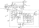
Фиг.2 - блок-схема перемежителя, который может быть использован в параллельном составном турбокодере фиг.1.FIG. 2 is a block diagram of an interleaver that can be used in a parallel composite turbo encoder of FIG. 1.
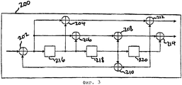
Фиг.3 - блок-схема составного кодера, который может быть использован вместе с перемежителем фиг.2.FIG. 3 is a block diagram of a composite encoder that can be used with the interleaver of FIG. 2.
Подробное описание предпочтительных вариантов осуществления изобретенияDETAILED DESCRIPTION OF PREFERRED EMBODIMENTS
В соответствии с одним вариантом осуществления изобретения, как проиллюстрировано на фиг.1, параллельный составной турбокодер 10, или турбокодер 10, содержит первый и второй кодеры 12, 14, перемежитель 16 и мультиплексор 18. Первый кодер 12 и перемежитель 16 выполнены с возможностью приема входных данных 20 кодера, которые обычно являются пользовательской информацией или данными управления. Первый кодер 12 выводит систематические символы 22, которые являются обычно копией исходных входных битов 20, и символы 24 контроля по четности. Второй кодер 14 выполнен с возможностью приема перемежающегося выходного сигнала 26 перемежителя 16 и для вывода второго множества символов 28 контроля по четности. Систематические символы (не изображены), генерируемые вторым кодером 14, сжимаются, а остальные соответствующие выходные сигналы 22, 24, 28 первого и второго кодеров 12, 14 мультиплексируются мультиплексором 18 в поток 30 выходных данных.In accordance with one embodiment of the invention, as illustrated in FIG. 1, a parallel composite turbo encoder 10, or turbo encoder 10, comprises first and second encoders 12, 14, interleaver 16 and multiplexer 18. The first encoder 12 and interleaver 16 are configured to receive input encoder data 20, which is typically user information or control data. The first encoder 12 outputs systematic symbols 22, which are typically a copy of the original input bits 20, and parity symbols 24. The second encoder 14 is configured to receive an interleaved output signal 26 of the interleaver 16 and to output the second plurality of parity symbols 28. Systematic symbols (not shown) generated by the second encoder 14 are compressed, and the remaining corresponding output signals 22, 24, 28 of the first and second encoders 12, 14 are multiplexed by the multiplexer 18 into the output stream 30.
Дополнительные пары кодера и перемежителя могут быть добавлены параллельно для уменьшения скорости кодирования, таким образом, обеспечивая улучшенное упреждающее исправление ошибок. Альтернативно некоторые из систематических символов 22 и/или символов 24 контроля по четности могут быть проколоты для увеличения скорости кодирования и обеспечения улучшенной спектральной эффективности.Additional encoder and interleaver pairs can be added in parallel to reduce the coding rate, thus providing improved forward error correction. Alternatively, some of the systematic symbols 22 and / or parity symbols 24 may be punctured to increase the coding rate and provide improved spectral efficiency.
Первый и второй кодеры 12, 14 могут быть кодерами различных типов, известными в данной области техники, включая блочные кодеры и сверточные кодеры. Примерные блочные кодеры и сверточные кодеры описаны в статье Бернарда Склара в журнале Digital Communication, 245-380 (1988). Первый и второй кодеры 12, 14 являются преимущественно сверточными кодерами с относительно малыми ограниченными длинами К, такими как, например, К=4, таким образом, обеспечивая уменьшенную сложность, поскольку малые ограниченные длины уменьшают сложность соответствующих декодеров (не изображены). Первый и второй кодеры 12, 14 также преимущественно являются рекурсивными систематическими сверточными (РСС) кодерами, которые известны в данной области техники. Перемежитель 16 преимущественно является двумерным перемежителем, как описано ниже.The first and second encoders 12, 14 may be various types of encoders known in the art, including block encoders and convolutional encoders. Exemplary block encoders and convolutional encoders are described in an article by Bernard Sklar in Digital Communication, 245-380 (1988). The first and second encoders 12, 14 are predominantly convolutional encoders with relatively small limited lengths K, such as, for example, K = 4, thus providing reduced complexity, since small limited lengths reduce the complexity of the respective decoders (not shown). The first and second encoders 12, 14 are also predominantly recursive systematic convolutional (PCC) encoders that are known in the art. The interleaver 16 is advantageously a two-dimensional interleaver, as described below.
Обычно первый и второй кодеры 12, 14 выводят два символа 24, 28 контроля по четности для каждого принимаемого бита 20, давая скорость кодирования R=1/2 для каждого кодера 12, 14. Тем не менее, общая скорость кодирования для турбокодера 10 равна 1/3, поскольку систематический бит из второго кодера прокалывается.Typically, the first and second encoders 12, 14 output two parity symbols 24, 28 for each received bit 20, giving a coding rate of R = 1/2 for each encoder 12, 14. However, the overall coding rate for turbo encoder 10 is 1 / 3, since the systematic bit from the second encoder is punctured.
Как изображено на фиг.2, двумерный (2-D) перемежитель 100 линейной конгруэнтной последовательности (ЛКП) в соответствии с одним вариантом осуществления изобретения содержит четыре справочных таблицы (СТ) 102, 104, 106, 108, семь двухвходовых мультиплексоров (МП) 110, 112, 114, 116, 118, 120, 122 и R-входовый мультиплексор 124, счетчик 126 строки, первый и второй логические блоки 128, 130 инвертирования бит, модуль 132 проверки правильности адреса, множество R регистров 134, 136, 138, 140 индекса столбца или строки (изображенных для простоты как четыре регистра), регистр 142 для маркировки сброса индекса столбца, первый и второй k-битовые мультиплексоры 144, 146 и четыре k-битовых сумматора 148, 150, 152, 154. Генератор 156 рекурсии ЛКП изображен пунктирной линией. Перемежитель 100 может использоваться параллельно составному турбокодеру фиг.1 или альтернативно перемежитель 100 может использоваться последовательно составному турбокодеру, в котором перемежитель 100 расположен снаружи или внутри составных кодеров, что очевидно специалистам в данной области техники.As shown in figure 2, the two-dimensional (2-D) interleaver 100 linear congruent sequence (LCP) in accordance with one embodiment of the invention contains four look-up tables (ST) 102, 104, 106, 108, seven two-input multiplexers (MP) 110 , 112, 114, 116, 118, 120, 122 and R-
Размер перемежителя 100 равен N, которое меньше или равно 2m и больше 2m-1. Число строк R, умноженное на число столбцов С, равно 2m. Число столбцов С равно 2k, т.е. k=log2C. Число строк R равно 2r, т.е. r=log2R.The size of the
Модуль 132 проверки правильности адреса может быть преимущественно реализован в виде логической схемы на дискретных вентильных элементах, сконфигурированной как сдвиговый регистр и сумматор. Модуль 132 проверки правильности адреса служит для проверки, меньше ли вход Х, чем произведение номера С столбца и входа Y (индекса строки), сложенных с входом Z (индексом столбца), выполняя, например, функцию сдвига и суммирования. Модуль 132 проверки правильности адреса служит для генерирования маркера, который указывает, является ли адрес неправильным, т.е. содержит ли адрес избыточные биты степени 2 (т.е. находится ли размер перемежителя между последовательными степенями 2), которые должны быть отброшены.The
Генератор 156 рекурсии ЛКП служит для псевдослучайного переупорядочения, или тасования, значений бит, содержащихся в каждой строке перемежителя 100, как описано ниже, с помощью приема значения номера строки на входах в четыре СТ 102, 104, 106, 108 и генерирования индекса столбца (входа Z в модуль 132 проверки правильности адреса). Специалистам в данной области техники будет понятно, что в параллельном составном турбокодере, таком как проиллюстрирован на фиг.1, физическое переупорядочение элементов данных можно преимущественно обойти в пользу использования псевдослучайно генерируемой ЛКП на считывании, адресуемом вторым кодером. Первый и второй логические блоки 128, 130 инвертирования бит служат для переупорядочения, или тасования, строк в перемежителе 100 в соответствии с заданным правилом инвертирования бит, как описано ниже и известно в данной области техники.The
СТ 102, 104, 106, 108 могут быть реализованы в виде некоторого запоминающего средства, известного в данной области техники. Первая СТ 102 используется для хранения значений коэффициента с. Вторая СТ 104 используется для хранения значений коэффициента а. Третья СТ 106 используется для хранения значений коэффициента а, взятого в степени коэффициента b. Четвертая СТ 108 используется для хранения значений ×(-1). Размер каждой СТ 102, 104, 106, 108 равен r×k битов. Общими требованиями к памяти для перемежителя 100 являются 4r×k битов плюс r×k битов регистров для регистров 134, 136, 138, 140.
Регистр 142 принимает значение бит, определяющее номер строки, который первоначально устанавливается равным R-1. С каждым циклом обработки регистр 142 выводит значение бит, означающее номер столбца, который первоначально устанавливается не равным нулю. Регистр 142, таким образом, служит для сброса индекса столбца каждый раз, когда номер строки циклически проходит через все строки.
С каждым циклом обработки входной МП 110 генерирует значение либо 1, либо -1, в зависимости от того, установлен ли маркер выполнения в обратном направлении. Это значение подается в сумматор 148, который суммирует это значение со значением бита, обозначенного NextRow (следующая строка). Результирующая сумма подается на вход данных счетчика 126 строки. Значение 1 подается на второй вход счетчика 126 строки. Счетчик 126 строки создает значение строки (хранимое первоначально как R-1 в регистре 142), которое подается во второй логический блок 130 инвертирования бит. Значение строки также подается в каждую из СТ 102, 104, 106, 108. Значение строки также подается в сумматор 150, который суммирует значение строки со значением 1 и подает результирующую сумму в первый логический блок 128 инвертирования бит.Эта результирующая сумма также подается на первый вход МП 112.With each processing cycle, the
С каждым циклом обработки первый логический блок 128 инвертирования бит подает некоторое значение на первый вход МП 114. Второй логический блок 130 инвертирования бит подает значение индекса строки на второй вход МП 114, а также на вход Y модуля 132 проверки правильности адреса. Модуль 132 проверки правильности адреса принимает значение N на входе Х. Модуль 132 проверки правильности адреса принимает значение а, основанное на хранимых коэффициентах, на входе Z. Модуль 132 проверки правильности адреса ЛКП вычисляет произведение С и значения входа Y, суммирует произведение со значением входа Z и проверяет, является ли результат больше или равным значению N на входе Х. Если вычисленное значение больше или равно N, модуль 132 проверки правильности адреса выводит значение 1. Иначе значение выхода равно 0. Выходное значение является маркером, обозначенным Addr_GT_N, который, когда установлен в 1, означает, что размер перемежителя находится между последовательными степенями 2, так что избыточные биты после более низкой степени 2 должны быть отброшены.With each processing cycle, the first bit
Значение Addr_GT_N подается в виде селекторного входного сигнала в МП 112, 114, 120 и 122. МП 112 выбирает свой первый вход, если значение Addr_GT_N установлено в 1. Выбранный входной сигнал, который выводится из МП 112, является перемежающимся значением NextRow. МП 114 выбирает свой первый вход, если значенеие Addr_GT_N установлено в 1. Выбранный входной сигнал, который выводится из МП 114, представляет значение индекса конечной строки.The value Addr_GT_N is supplied as a selector input signal to the
Генерация рекурсии ЛКП выполняется следующим образом. С каждым циклом обработки k-битовое значение, представляющее коэффициент с, посылается из первой СТ 102 в k-битовый сумматор пути данных. Значение а посылается из второй СТ 104 на первый вход МП 116. Значение, представляющее а, взятое в степени b, посылается из третьей СТ 106 на второй вход МП 116. МП 116 принимает маркер RunBackwards (выполнения в обратном порядке) на селекторном входе. Если значение RunBackwards равно 1, МП 116 выбирает свой второй вход и подает выбранное значение, k-битовое значение, в умножитель 144. Иначе МП 116 подает свой первый входной сигнал, k-битовое значение, в умножитель 144. Значение ×(-1) посылается из четвертой СТ 108 на первый вход МП 118. МП 118 принимает на втором входе k-битовое значение, выведенное из МП 124. МП 118 принимает значение индекса столбца в качестве селекторного индекса. Значение индекса столбца первоначально устанавливается не равным нулю. Если значение индекса столбца равно 1, МП 118 выбирает свой второй вход. Иначе МП 118 выбирает свой первый вход. Выбранное входное значение, k-битовое значение, подается в умножитель 144. Результирующее произведение из умножителя 144 подается в k-битовый сумматор 152. Преимущественно k-битовый сумматор 152 пути данных является программируемым сумматором/вычитающим устройством, который известен в данной области техники. Когда перемежитель 100 производит выполнение в обратном направлении, сумматор 152 вычитает значение с.LPC recursion generation is performed as follows. With each processing cycle, a k-bit value representing coefficient c is sent from the
k-Битовый сумматор 152 подает выходное значение с каждым циклом обработки на вход Z модуля 132 проверки правильности адреса. Выходной сигнал сумматора 152 также подается на первый вход МП 120 и в каждый из регистров 136, 138, 140 первой по (R-1)-й строки. Выходной сигнал сумматора 152 также подается как k-битовое входное значение на первый вход МП 122.The k-
МП 120 принимает второе входное значение из k-битового сумматора 154. Если селекторный вход МП 120 установлен в 1, МП 120 выбирает свой первый вход. Иначе МП 120 выбирает свой второй вход. Выбранный входной сигнал подается в регистр 134 нулевой строки. Каждый регистр 134, 136, 138, 140 строки подает выходное значение на соответствующие входы МП 124. Дополнительно выходное значение из регистра 134 нулевой строки подается в умножитель 146. МП 124 принимает значение строки (выходной сигнал счетчика 126 строки) на селекторном входе. Входной сигнал регистра строки, выбранный МП 124, зависит от значения строки на селекторном входе. Таким образом, каждый регистр 134, 136, 138, 140 строки обновляется, когда значение строки равно соответствующему номеру регистра строки, а регистр 134 нулевой строки также включается, когда маркер Addr_GT_N равен нулю.
k-Битовое начальное входное значение b для R=0 подается в умножитель 146. Умножитель 146 также принимает значение, выведенное из регистра 134 нулевой строки. Умножитель 146 умножает два принимаемых значения вместе и подает результирующее произведение в k-битовый сумматор 154. k-Битовый сумматор 154 пути данных также принимает начальное входное значение с для R=0. Преимущественно k-битовый сумматор 154 пути данных является программируемым сумматором/устройством вычитания, который известен в данной области техники. Когда перемежитель 100 работает в обратном направлении, сумматор 154 вычитает начальное значение с. Сумматор 154 суммирует (или, как запрограммирован, вычитает) два принятых значения. Результирующая сумма, k-битовое значение, подается на второй вход МП 122.The k-bit initial input value b for R = 0 is supplied to the
МП 122 выбирает свой первый вход, если его селекторный вход установлен в 1. Иначе МП 122 выбирает свой второй вход. МП 122 выводит выбранный входной сигнал как значение индекса конечного столбца. Адрес для следующего значения бита является произведением R и значения индекса конечного столбца, выведенного из МП 122, просуммированного со значением индекса конечного столбца, выведенным из МП 114.
В одном варианте осуществления ЛКП с периодом М рекурсивно генерируется в соответствии со следующим тождеством:In one embodiment, an LCP with period M is generated recursively in accordance with the following identity:
x(n+1)=(ax(n)+c)modM x (n + 1) = (ax (n) + c) modM
с целыми а, с и М, удовлетворяющими следующим трем условиям: (1) с должно быть взаимно простым для М. (2) а-1 должно быть кратным p, где p - любое простое число, которое делит М. Когда М является кратным 4, а-1 должно быть кратно 4. (3) ×(0) является значением начального числа, которое может быть любым целым. Для упрощения реализации М может быть преимущественно выбрано равным степени 2. Таким образом, а должно быть в виде 4р+1, в то время как с может быть взято как любое нечетное число. Следует заметить, что в то время как ×(0) используется выше для обозначения начального условия, ×(-1) используется для обозначения начального условия в варианте осуществления изобретения, описанном в связи с фиг.2. Никакое значение не должно придаваться различным используемым числам.with integers a, c and M satisfying the following three conditions: (1) c must be coprime for M. (2) a-1 must be a multiple of p, where p is any prime number that divides M. When M is a multiple 4, a-1 must be a multiple of 4. (3) × (0) is the value of the initial number, which can be any integer. To simplify the implementation, M can be advantageously chosen equal to degree 2. Thus, a should be in the form 4p + 1, while c can be taken as any odd number. It should be noted that while × (0) is used above to indicate the initial condition, × (-1) is used to indicate the initial condition in the embodiment of the invention described in connection with FIG. 2. No meaning should be given to the various numbers used.
2-D перемежитель ЛКП в соответствии с одним вариантом осуществления изобретения определяется следующим образом: допуская размер перемежения равным K=2N, перемежитель определяется как прямоугольная матрица с R строками и С столбцами, где R и С даются степенями 2. Перемежаемые данные записываются в матрицу по строкам. Строки данных сначала перестанавливаются (т.е. перемежаются) в соответствии с любым традиционным правилом перемежения. Преимущественно строки данных перестанавливаются в соответствии с правилом инвертирования бит, применяемым к индексу строки. Внутри каждой строки столбцы (т.е. элементы данных, так как каждый столбец имеет один элемент данных на строку) перестанавливаются в соответствии с правилом, определяемым связанной ЛКП. ЛКП, связанные с двумя различными строками, являются преимущественно различными, но могут быть в альтернативе одинаковыми. После перестановки всех строк данные считываются по столбцам для выдачи перемежающейся последовательности. Специалистам в данной области техники будет понятно, что перемежитель с длиной, меньшей 2N и большей 2N-1, может быть сгенерирован удалением неправильных адресов из перемежителя длины 2N.The 2-D LK interleaver in accordance with one embodiment of the invention is defined as follows: assuming the interleave size is K = 2 N , the interleaver is defined as a rectangular matrix with R rows and C columns, where R and C are given by powers of 2. Interleaved data is written to the matrix line by line. Data rows are first rearranged (i.e., interleaved) in accordance with any traditional interleaving rule. Mostly data rows are rearranged according to the bit inversion rule applied to the row index. Within each row, columns (i.e., data elements, since each column has one data element per row) are rearranged according to the rule defined by the associated LCP. LCPs associated with two different lines are predominantly different, but may alternatively be the same. After rearranging all the rows, the data is read in columns to produce an interleaved sequence. Those skilled in the art will appreciate that interleaver with length less than 2 and greater than 2 N N-1 may be generated by removing incorrect addresses from an interleaver of length 2 N.
В одном варианте осуществления изобретения 2-D перемежитель ЛКП включает следующие технические условия: размер перемежителя равен 32 (т.е. N=5), а массив данных определяется как {d(0), d(1), d(2), ... d(31)}. Перемежитель организован как массив с четырьмя строками и восьмью элементами в строке. Элементы данных заполняются по строкам следующим образом:In one embodiment, the 2-D LK interleaver includes the following specifications: the interleaver size is 32 (i.e., N = 5), and the data array is defined as {d (0), d (1), d (2), ... d (31)}. The interleaver is organized as an array with four rows and eight elements per row. Data items are populated row by row as follows:

Индексы строки в двоичном виде (00, 01, 10, 11) могут быть преимущественно инвертированы по битам (т.е. 00, 10, 01, 11), а строки переставлены таким образом, чтобы получитьThe binary row indices (00, 01, 10, 11) can be predominantly inverted by bits (i.e. 00, 10, 01, 11), and the rows are rearranged in such a way as to obtain

Инвертирование бит служит для тасования строк перемежителя в соответствии с заданным алгоритмом инвертирования бит. Применение алгоритма инвертирования бит обеспечивает желаемое временное разделение между строками перемежителя. Тем не менее, инвертирование бит не обязательно для реализации перемежителя.Bit inversion is used to shuffle interleaver lines in accordance with a given bit inversion algorithm. The application of the bit inversion algorithm provides the desired time separation between the interleaver lines. However, inverting bits is not necessary to implement an interleaver.
В конкретном варианте осуществления изобретения перестановка ЛКП генерируется в соответствии со следующими уравнениями:In a specific embodiment of the invention, the permutation of the LPC is generated in accordance with the following equations:
x1(n+1)=(5x1(n)+7)mod8, c x1(0)=3,x 1 (n + 1) = (5x 1 (n) +7) mod8 , cx 1 (0) = 3,
x2(n+1)=(x2(n)+5)mod8, с x2(0)=0,x 2 (n + 1) = (x 2 (n) +5) mod8 , with x 2 (0) = 0,
x3(n+1)=(5x3(n)+3)mod8, с x3(0)=4,x 3 (n + 1) = (5x 3 (n) +3) mod8 , s x 3 (0) = 4,
иand
x4(n+1)=(x4(n)+3)mod8, c x4(0)=3.x 4 (n + 1) = (x 4 (n) +3) mod8, cx 4 (0) = 3.
Конфигурации перестановки задаются {3, 6, 5, 0, 7, 2, 1, 4}, {0, 5, 2, 7, 4, 1, 6, 3}, {4, 7, 6, 1, 0, 3, 2, 5} и {7, 2, 5, 0, 3, 6, 1, 4} для четырех строк соответственно. Таким образом, после применения перестановки столбцов первая строка становитсяPermutation configurations are given by {3, 6, 5, 0, 7, 2, 1, 4}, {0, 5, 2, 7, 4, 1, 6, 3}, {4, 7, 6, 1, 0, 3, 2, 5} and {7, 2, 5, 0, 3, 6, 1, 4} for four lines, respectively. Thus, after applying column permutation, the first row becomes
(d(3) d(6) d(5) d(0) d(7) d(2) d(1) d(4)),(d (3) d (6) d (5) d (0) d (7) d (2) d (1) d (4)),
вторая строка становитсяsecond line becomes
(d(16) d(21) d(18) d(23) d(20) d(17) d(22) d(19)),(d (16) d (21) d (18) d (23) d (20) d (17) d (22) d (19)),
третья строка становитсяthird row becomes
{d(12) d(15) d(14) d(9) d(8) d(11) d(10) d(13)},{d (12) d (15) d (14) d (9) d (8) d (11) d (10) d (13)},
и четвертая строка становитсяand the fourth line becomes
{d(31) d(26) d(29) d(24) d(27) d(30) d(25) d(28)}{d (31) d (26) d (29) d (24) d (27) d (30) d (25) d (28)}
После того как все столбцы переставлены внутри соответствующих им строк, матрица перемежающихся данных имеет следующий вид:After all the columns are rearranged inside the rows corresponding to them, the matrix of interleaved data has the following form:

Данные в перемежающейся матрице считываются по столбцам, выдавая следующую перемежающуюся последовательность: {d(3), d(16), d(12), d(31), d(6), d(21), d(15), d(26), d(5), d(18), d(14), ..., d(11), d(30), d(1), d(22), d(10), d(25), d(4), d(19), d(13), d(28)}. Если требуется перемежитель длины 30, перемежитель, генерируемый, как описано выше, может быть укорочен удалением элементов данных d(30) и d(31), создавая следующую перемежающуюся последовательность: {d(3), d(16), d(12), ![]()
![]()
![]()
![]()
ЛКП, используемые в конструкции перемежителя, могут быть сгенерированы либо в прямом, либо в обратном направлении, как требуется, для оптимального использования с декодерами протокола МАР в турбодекодировании. В одном варианте осуществления изобретения генерирование обратной последовательности задается следующим уравнением:The paintwork used in the interleaver design can be generated either in the forward or in the reverse direction, as required, for optimal use with MAP decoders in turbo decoding. In one embodiment of the invention, the generation of the negative sequence is given by the following equation:
x(n)=(aβx(n+1)-c)modM,x (n) = (a β x (n + 1) -c) modM ,
гдеWhere
β=(M1/2)-1.β = (M 1/2 ) -1.
Следует заметить, что элемент β, который используется в вышеприведенных уравнениях, представляет коэффициент b, описанный в связи с вариантом осуществления изобретения по фиг.2.It should be noted that the element β, which is used in the above equations, represents the coefficient b described in connection with the embodiment of the invention of FIG. 2.
Таким образом, генерирование последовательностей ЛКП требует, чтобы каждый перемежитель был однозначно определен параметрами 3R, где R - число строк. Требуется относительно короткий умножитель log2(C)×log2(С). Благодаря операции по модулю не требуется генерирование битов выше ячейки бит log2(C). Для хранения промежуточных результатов R конгруэнтных последовательностей требуется одно множество R регистров.Thus, the generation of LPC sequences requires that each interleaver be uniquely determined by the parameters 3R, where R is the number of rows. A relatively short log 2 (C) × log 2 (C) multiplier is required. Thanks to the modulo operation, the generation of bits above the cell of the log 2 (C) bits is not required. To store intermediate results of R congruent sequences, one set of R registers is required.
Для каждой строки с различными параметрами ×(0), а и b имеются многие различные возможности для перестановки последовательностей. Желательно выполнить исследование для оптимизации параметров перемежителя для использования с конкретными турбокодами.For each row with different parameters × (0), a and b, there are many different possibilities for rearranging sequences. It is advisable to carry out a study to optimize the interleaver parameters for use with specific turbo codes.
На фиг.3 составной кодер 200 в соответствии с одним вариантом осуществления изобретения оптимизирован для конкретного турбокода, используемого в цифровых беспроводных коммуникационных системах МДКР (множественного доступа с кодовым разделением каналов). Кодер 200 содержит семь сумматоров 202, 204, 206, 208, 210, 212, 214 по модулю 2 и три ячейки 216, 218, 220 бит. Ячейки 216, 218, 220 бит могут быть реализованы как трехбитовый регистр или альтернативно три однобитовых регистра. Сумматоры 202, 204, 206, 208, 210, 212, 214 по модулю 2 соединяются с ячейками 216, 218, 220 бит точным способом так, чтобы создавать требуемое множество отводов обратной связи. Таким образом, сумматор 202 выполнен с возможностью приема входного бита. Сумматор 202 также соединяется с ячейкой 216 бит и с сумматорами 204 и 206. Ячейка 216 бит соединяется с ячейкой 218 бит и с сумматорами 204 и 206. Ячейка 218 бит соединяется с ячейкой 220 бит и с сумматорами 208 и 210. Сумматор 210 соединяется с сумматором 202. Сумматор 204 соединяется с сумматором 212. Сумматор 206 соединяется с сумматором 208. Сумматор 208 соединяется с сумматором 214. Ячейка 220 бит соединяется с сумматорами 210, 214 и 212. Сумматоры 212, 214 выполнены с возможностью вывода соответственно первого и второго символов.3, a
В данной области техники известно, что эффективность ошибки может быть определена входным и выходным весовым коэффициентом событий ошибки в составных декодерах (не изображены). Смотри, например, S. Benedetto & G. Montorsi, Unveiling Turbo Codes: Some Results on Parallel Concatenated Coding Schemes, 42 IEEE Trans. Info. Theory 409-28 (март 1996). Входной весовой коэффициент события ошибки равен числу ошибок в битах, тогда как выходной весовой коэффициент события ошибки равен числу ошибок кодового символа. Событие ошибки входного весового коэффициента 1 очевидно будет отклоняться от состояния всех нулей и никогда повторно не объединится (1 будет циклически повторяться бесконечно в сдвиговом регистре, накапливая все больший выходной весовой коэффициент вдоль пути). Это происходит из-за рекурсивной, или обратной, связи части кодера. Благодаря этой структуре было показано, что эффективность турбокодов при высоком отношении сигнала к шуму (ОСШ) подавляется событиями выходной ошибки с входным весовым коэффициентом 2. Минимальный уровень ошибки турбокода может быть точно предсказан, используя так называемую асимптоту эффективного произвольного отклонения. Эффективное произвольное отклонение равно минимальному выходному весовому коэффициенту всех событий ошибки входного весового коэффициента 2. События ошибки входного весового коэффициента 2, которые являются короткими по длительности, будут обычно вызывать события ошибки минимального отклонения. Для кодера 200 фиг.3 полином обратной связи равен 1+D2+D3, а все возможные события ошибки входного весового коэффициента 2 представляются в виде Dk (1+D7j), где j=1, 2, ..., а k - произвольный сдвиг в диапазоне 0, ..., K-7j (предполагается, что К является размером перемежителя). Это может быть легко проверено исследованием решеток составного кодера 200, что очевидно для специалистов в данной области техники.It is known in the art that error efficiency can be determined by the input and output weights of error events in composite decoders (not shown). See, for example, S. Benedetto & G. Montorsi, Unveiling Turbo Codes: Some Results on Parallel Concatenated Coding Schemes, 42 IEEE Trans. Info Theory 409-28 (March 1996). The input weight of the error event is equal to the number of errors in bits, while the output weight of the error event is equal to the number of errors of the code symbol. The error event of the
Следует заметить, что размер перемежителя для варианта осуществления изобретения по фиг.3 обозначен K, в то время как размер перемежителя для варианта осуществления изобретения по фиг.2 обозначен N. Специалистам в данной области техники будет понятно, что использование различных букв не имеет никакого специального значения.It should be noted that the interleaver size for the embodiment of FIG. 3 is denoted by K, while the interleaver size for the embodiment of FIG. 2 is denoted by N. Those skilled in the art will understand that the use of different letters has no special values.
Предположим, например, что конфигурация ошибки Dk (1+D7) вызывает событие ошибки минимального отклонения из первого декодера. Турбоперемежитель будет отображать две ошибки (Dk, Dk+7) в две позиции (Dn, Dm). Если |m-n|=7 или равно некоторому числу, кратному 7, вероятным является событие ошибки малого отклонения из второго декодера. Основным назначением турбоперемежителя является не допускать появления таких отображений. А именно перемежитель должен преимущественно отображать совокупности битов, которые склонны к событиям ошибки низкого весового коэффициента, в первом измерении, в совокупности битов, которые генерируют большую величину выходного весового коэффициента, во втором измерении. Таким образом, желаемым подходом к проектированию перемежителя является попытка не допустить отображения пар бит, расположенных в индексах (k, k+7j), в пары бит, расположенных в индексах (s, s+7t), с особым акцентом на меньшие значения j и t. Такие события входной ошибки перечислены в таблице 1 ниже. Для каждого события перечислен выходной весовой коэффициент контроля по четности первого составного кода при использовании соответствующих конфигураций прокола для турбокодов прямой линии связи скорости 1/2, 1/3 и 1/4, как определено в IS-95.Suppose, for example, that the configuration of the error D k (1 + D 7 ) causes a minimum deviation error event from the first decoder. The interleaver will display two errors (D k , D k + 7 ) in two positions (D n , D m ). If | mn | = 7 or is equal to a multiple of 7, the event of a small deviation error from the second decoder is probable. The main purpose of the turbo interleaver is to prevent the appearance of such mappings. Namely, the interleaver should advantageously display a set of bits that are prone to low weight error events, in the first dimension, in a set of bits that generate a large output weight coefficient, in the second dimension. Thus, the desired approach to the design of the interleaver is an attempt to prevent the mapping of pairs of bits located in the indices (k, k + 7j) into pairs of bits located in the indices (s, s + 7t), with particular emphasis on lower values of j and t. Such input error events are listed in table 1 below. For each event, the output weighting coefficient of the parity of the first composite code is listed using the appropriate puncture configurations for the forward
События входной ошибки весового коэффициента 2Table 1
Weighting Input Error 2 Events
Если данный перемежитель содержит отображение входного весового коэффициента 2→2 в виде Dk1(1+D7)→Dk2(1+D7), тогда составной выходной весовой коэффициент события результирующей ошибки будет равен 2+3+3=8 для турбокода скорости 1/2. В предыдущем вычислении весовой коэффициент систематических битов (2) суммируется с соответствующим весовым коэффициентом проверки по четности из двух составных кодеров (3 и 3). Аналогично, если перемежитель содержит отображение входного весового коэффициента 2→2 в виде Dk1(1+D7)→Dk2(1+D14), тогда составной выходной весовой коэффициент события результирующей ошибки будет равен 2+3+6=11 для турбокода скорости 1/2 или 2+6+10=18 для турбокода скорости 1/3.If this interleaver contains a display of the input weight coefficient 2 → 2 in the form D k1 (1 + D 7 ) → D k2 (1 + D 7 ), then the composite output weight coefficient of the resulting error event will be 2 + 3 + 3 = 8 for the
Кроме того, возможно, что события входной ошибки весового коэффициента 4 низкого составного выходного весового коэффициента могут отображаться в два события входной ошибки весового коэффициента 2 низкого выходного весового коэффициента во втором измерении. Такие отображения обозначаются 4→{2, 2}. Несмотря на то что не имеется решения законченного вида для событий составной ошибки входного весового коэффициента 4, следующая таблица содержит некоторые из событий ошибки низкого выходного весового коэффициента для составного кодера 200, где составной кодер 200 используется как первый составной кодер для турбокодов прямой линии связи в цифровой беспроводной коммуникационной системе МДКР, использующей воздушный интерфейс, извлеченный из IS-95.In addition, it is possible that the events of the input error of the weight coefficient 4 of the low composite output weight coefficient can be displayed in two events of the input error of the weight coefficient 2 of the low output weight coefficient in the second dimension. Such mappings are denoted by 4 → {2, 2}. Although there is no complete solution for composite input error events of weight 4, the following table contains some of the low output weight error events for
События входной ошибки весового коэффициента 4table 2
Weighting Input Error 4 Events
Если, например, перемежитель содержит отображение входного весового коэффициента 4→{2,2} в виде Dk1(1+D3+D4+D5)→{Dk2(1+D7)Dk3(1+D7)}, тогда составной выходной весовой коэффициент события результирующей ошибки будет равен 4+2+3+3=12 для турбокода скорости 1/2. Это событие составной ошибки незначительно хуже, чем событие ошибки из-за отображения Dk1(1+D7)→Dk2(1+D14), которое имеет составной выходной весовой коэффициент 11. Первостепенной задачей проектирования, таким образом, является оптимизация параметров перемежителя так, что вышеописанные типы плохого отображения исключаются или, по меньшей мере, минимизируются. Идеально плохие отображения, имеющие самый низкий составной весовой коэффициент, являются отображениями, наиболее важными для исключения и/или минимизации. При проектировании перемежителя для конкретного размера (например, 1530) возможно оптимизировать параметры премежителя так, чтобы минимизировать оба типа отображений (т.е. весового коэффициента 2→2 и весового коэффициента 4→{2, 2}. Этот подход выдает оптимальный перемежитель для этого конкретного размера. Следует заметить, что при проектировании перемежителя размера 2N, который может быть надежно проколот до размера, большего 2N-1 (который называется перемежителем "дружелюбного прокола"), оптимизация для отображений 4→{2, 2} весового коэффициента может быть более трудной для достижения.If, for example, the interleaver contains a mapping of the input weight coefficient 4 → {2,2} in the form D k1 (1 + D 3 + D 4 + D 5 ) → {D k2 (1 + D 7 ) D k3 (1 + D 7 )}, then the composite output weight coefficient of the resulting error event will be 4 + 2 + 3 + 3 = 12 for the
Было проведено исследование для получения перемежителей дружелюбного прокола размера 2N из 2-D перемежителя ЛКП в соответствии с вариантом осуществления изобретения по фиг.3. Таблица 3 ниже содержит начальные результаты исследования. Для каждого размера перемежителя число используемых строк и число используемых столбцов определяются вместе с коэффициентами ×(0), а и с. Для простоты и эффективности в реализации тридцать две строки использовались для всех перемежителей.A study was conducted to obtain a 2 N -friendly puncture interleaver from a 2-D LK interleaver in accordance with the embodiment of FIG. 3. Table 3 below contains the initial results of the study. For each interleaver size, the number of rows used and the number of columns used are determined together with the coefficients × (0), а and с. For simplicity and efficiency in implementation, thirty-two lines were used for all interleavers.
Коэффициенты 2-D перемежителя ЛКПTable 3
Coefficients 2-D interleaver LKP
В альтернативном варианте осуществления изобретения коэффициент а может быть установлен равным 1, причем было выполнено новое исследование для получения перемежителей "дружелюбного прокола" размера 2N из 2-D перемежителя ЛКП. Уравнения прямой и обратной рекурсии ЛКП упрощаются, соответственно, в следующие:In an alternative embodiment of the invention, the coefficient a can be set equal to 1, and a new study was performed to obtain 2 N friendly puncture interleavers from a 2-D LCP interleaver. The equations of direct and inverse recursion of LCPs are simplified, respectively, into the following:
х(n+1)=(x(n)+c)modMx (n + 1) = (x (n) + c) modM
иand
х(n)=(x(n+1)-c)modMx (n) = (x (n + 1) -c) modM
Таблица 4, приведенная ниже, содержит начальные результаты исследования. Для простоты и эффективности реализации тридцать два ряда использовались для всех перемежителей. Специалистам в данной области техники будет понятно из результатов, изображенных в таблице 4, что установка а равным 1 во всех рекурсиях ЛКП не порождает ухудшения в качестве результирующих перемежителей. Кроме того, выигрыши сложности, достигаемые из упрощения установки а равным 1, являются существенными. Например, вторая и третья СТ, описанные в вариантах осуществления изобретения по фиг.2 (СТ, используемые для хранения значений а и аb), не требуются. K-битовые умножители, описанные в варианте осуществления по фиг.2, являются также необязательными. Как видно из таблицы 4, приведенной ниже, только начальное условие ×(-1) и аддитивная константа с должны быть определены для каждой строки перемежителя. Коэффициенты для перемежителей большего размера не включены в таблицу, которая определяет только результаты начального исследования, поскольку их не было в наличии ко времени регистрации настоящей заявки.Table 4 below contains the initial results of the study. For simplicity and efficiency of implementation, thirty two rows were used for all interleavers. Those skilled in the art will appreciate from the results shown in Table 4 that setting a to 1 in all LCP recursions does not cause deterioration in the quality of the resulting interleavers. In addition, the complexity gains achieved by simplifying setting a to 1 are significant. For example, the second and third CTs described in the embodiments of FIG. 2 (CTs used to store values a and a b ) are not required. The K-bit multipliers described in the embodiment of FIG. 2 are also optional. As can be seen from table 4 below, only the initial condition × (-1) and the additive constant c must be defined for each row of the interleaver. Coefficients for larger interleavers are not included in the table, which determines only the results of the initial study, since they were not available at the time of registration of this application.
Коэффициенты 2-D перемежителя ЛКTable 4
LC Interleaver 2-D Coefficients
Таким образом, описан новый и усовершенствованный перемежитель турбокода, использующий линейные конгруэнтные последовательности. Специалистам в данной области техники будет понятно, что, несмотря на то что варианты осуществления изобретения, раскрытые в настоящем описании, описаны в контексте системы сотовой телефонной связи, признаки настоящего изобретения в равной степени годятся для применения в любом виде коммуникационных систем, включая, например, спутниковую коммуникационную систему. Специалистам в данной области техники дополнительно будет понятно, что варианты осуществления изобретения, описанные здесь, могут быть использованы для кодирования либо сообщений данных, либо речевых сообщений. Также будет понятно, что данные, инструкции, команды, информация, сигналы, биты, символы и элементарные сигналы, которые могут быть упомянуты на протяжении всего вышеприведенного описания, преимущественно представляются напряжениями, токами, электромагнитными волнами, магнитными полями или частицами, оптическими полями или частицами или любыми их сочетаниями.Thus, a new and improved turbo code interleaver using linear congruent sequences is described. Those skilled in the art will understand that while the embodiments disclosed herein are described in the context of a cellular telephone system, the features of the present invention are equally suitable for use in any form of communication system, including, for example, satellite communication system. Those skilled in the art will further appreciate that the embodiments of the invention described herein can be used to encode either data messages or voice messages. It will also be understood that data, instructions, commands, information, signals, bits, symbols, and elementary signals that may be mentioned throughout the above description are predominantly represented by voltages, currents, electromagnetic waves, magnetic fields or particles, optical fields or particles or any combination thereof.
Кроме того, специалистам в данной области техники понятно, что различные иллюстративные логические блоки и операции алгоритма, описанные в связи с вариантами осуществления изобретения, раскрытыми в настоящем описании, могут быть реализованы или выполнены с помощью процессора цифрового сигнала (ПЦС), специализированной интегральной схемы (СИС), дискретных вентильных или транзисторных логических элементов, дискретных компонентов технического обеспечения, таких как, например, регистры и память магазинного типа "первым пришел, первым обслужен", процессор, выполняющий множество команд встроенных программ, или любой традиционный программируемый модуль программного обеспечения и процессор. Процессор может быть преимущественно микропроцессором, но в альтернативе процессор может быть любым обычным процессором, контроллером, микроконтроллером или конечным автоматом. Модуль программного обеспечения мог бы находиться в памяти с произвольной выборкой, флэш-памяти, регистрах или любого другого вида считываемого запоминающего носителя информации, известного в данной области техники.In addition, it will be understood by those skilled in the art that various illustrative logical blocks and algorithm operations described in connection with the embodiments disclosed herein may be implemented or performed using a digital signal processor (DSP), a specialized integrated circuit ( SIS), discrete gate or transistor logic elements, discrete hardware components, such as, for example, registers and store-type memory "first come, first go supper, "a processor that executes many embedded program instructions, or any traditional programmable software module and processor. The processor may preferably be a microprocessor, but in the alternative, the processor may be any conventional processor, controller, microcontroller, or state machine. The software module could reside in random access memory, flash memory, registers, or any other kind of readable storage medium known in the art.
Таким образом, изображены и описаны предпочтительные варианты осуществления настоящего изобретения. Однако обычным специалистам в данной области техники будет очевидно, что многочисленные изменения могли бы быть сделаны для вариантов осуществления изобретения, раскрытых в настоящем описании, без отступления от сущности и объема изобретения. Таким образом, настоящее изобретение не должно ограничиваться ничем, кроме следующей формулы изобретения.Thus, preferred embodiments of the present invention are depicted and described. However, it will be apparent to those skilled in the art that numerous changes could be made to the embodiments disclosed herein without departing from the spirit and scope of the invention. Thus, the present invention should not be limited by anything other than the following claims.
Claims (12)
Applications Claiming Priority (2)
| Application Number | Priority Date | Filing Date | Title |
|---|---|---|---|
| US09/205,511 US6304991B1 (en) | 1998-12-04 | 1998-12-04 | Turbo code interleaver using linear congruential sequence |
| US09/205,511 | 1998-12-04 |
Related Parent Applications (1)
| Application Number | Title | Priority Date | Filing Date |
|---|---|---|---|
| RU2001118276/09A Division RU2235424C2 (en) | 1998-12-04 | 1999-12-03 | Turbo-code interleaving device using linear congruent sequences |
Related Child Applications (1)
| Application Number | Title | Priority Date | Filing Date |
|---|---|---|---|
| RU2007125429/09A Division RU2376702C2 (en) | 1998-12-04 | 2007-07-05 | Turbo decoder which uses linear congruent sequences |
Publications (2)
| Publication Number | Publication Date |
|---|---|
| RU2003107665A RU2003107665A (en) | 2004-09-20 |
| RU2313177C2 true RU2313177C2 (en) | 2007-12-20 |
Family
ID=22762490
Family Applications (3)
| Application Number | Title | Priority Date | Filing Date |
|---|---|---|---|
| RU2001118276/09A RU2235424C2 (en) | 1998-12-04 | 1999-12-03 | Turbo-code interleaving device using linear congruent sequences |
| RU2003107665/09A RU2313177C2 (en) | 1998-12-04 | 1999-12-03 | Turbo-decoder using linear congruent series |
| RU2007125429/09A RU2376702C2 (en) | 1998-12-04 | 2007-07-05 | Turbo decoder which uses linear congruent sequences |
Family Applications Before (1)
| Application Number | Title | Priority Date | Filing Date |
|---|---|---|---|
| RU2001118276/09A RU2235424C2 (en) | 1998-12-04 | 1999-12-03 | Turbo-code interleaving device using linear congruent sequences |
Family Applications After (1)
| Application Number | Title | Priority Date | Filing Date |
|---|---|---|---|
| RU2007125429/09A RU2376702C2 (en) | 1998-12-04 | 2007-07-05 | Turbo decoder which uses linear congruent sequences |
Country Status (15)
| Country | Link |
|---|---|
| US (2) | US6304991B1 (en) |
| EP (2) | EP2267903A3 (en) |
| JP (2) | JP4723089B2 (en) |
| KR (1) | KR100711326B1 (en) |
| CN (1) | CN1202625C (en) |
| AU (1) | AU763873B2 (en) |
| BR (1) | BR9915926A (en) |
| CA (1) | CA2353455C (en) |
| HK (1) | HK1045030B (en) |
| ID (1) | ID30087A (en) |
| MX (1) | MXPA01005573A (en) |
| NO (1) | NO20012708L (en) |
| RU (3) | RU2235424C2 (en) |
| UA (1) | UA63024C2 (en) |
| WO (1) | WO2000035103A1 (en) |
Families Citing this family (79)
| Publication number | Priority date | Publication date | Assignee | Title |
|---|---|---|---|---|
| DE19736626C1 (en) * | 1997-08-22 | 1998-12-10 | Siemens Ag | Data transmission method in digital transmission system |
| EP0998087A1 (en) * | 1998-10-30 | 2000-05-03 | Lucent Technologies Inc. | Multilevel transmission system and method with adaptive mapping |
| EP0998045A1 (en) * | 1998-10-30 | 2000-05-03 | Lucent Technologies Inc. | Digital transmission system and method |
| US6304991B1 (en) * | 1998-12-04 | 2001-10-16 | Qualcomm Incorporated | Turbo code interleaver using linear congruential sequence |
| US6871303B2 (en) * | 1998-12-04 | 2005-03-22 | Qualcomm Incorporated | Random-access multi-directional CDMA2000 turbo code interleaver |
| KR100306282B1 (en) | 1998-12-10 | 2001-11-02 | 윤종용 | Apparatus and for interleaving and deinterleaving frame date in communication system |
| US6625234B1 (en) * | 1998-12-10 | 2003-09-23 | Nortel Networks Limited | Efficient implementations of proposed turbo code interleavers for third generation code division multiple access |
| US6463556B1 (en) * | 1999-01-04 | 2002-10-08 | Motorola, Inc. | Method and apparatus for interleaving in a communication system |
| JP3746426B2 (en) * | 1999-02-26 | 2006-02-15 | 富士通株式会社 | Turbo decoder |
| CA2266283C (en) * | 1999-03-19 | 2006-07-11 | Wen Tong | Data interleaver and method of interleaving data |
| JP3574405B2 (en) * | 1999-04-06 | 2004-10-06 | サムスン エレクトロニクス カンパニー リミテッド | Two-dimensional interleaving apparatus and method |
| CA2742096C (en) * | 1999-04-13 | 2015-01-06 | Ericsson Ab | Rate matching and channel interleaving for a communications system |
| FR2792476B1 (en) * | 1999-04-13 | 2001-06-08 | Canon Kk | ARQ TYPE METHOD FOR TRANSMISSION METHOD USING TURBO-CODES, AND ASSOCIATED DEVICE |
| US6543013B1 (en) * | 1999-04-14 | 2003-04-01 | Nortel Networks Limited | Intra-row permutation for turbo code |
| US6377607B1 (en) * | 1999-05-13 | 2002-04-23 | Qualcomm Incorporated | System and method for performing accurate demodulation of turbo-encoded signals via pilot assisted coherent demodulation |
| CN100574116C (en) | 1999-05-19 | 2009-12-23 | 三星电子株式会社 | Turbo-interleaving device and method |
| ID27977A (en) * | 1999-07-08 | 2001-05-03 | Samsung Electronics Co Ltd | APARATUS AND METHODS TO CONTROL DEMULTIPLEXORS AND MULTIPLEXORS USED FOR ADJUSTMENT OF SPEED IN MOVING COMMUNICATION SYSTEMS |
| EP1085660A1 (en) * | 1999-09-15 | 2001-03-21 | TELEFONAKTIEBOLAGET L M ERICSSON (publ) | Parallel turbo coder implementation |
| US6687870B1 (en) * | 1999-09-23 | 2004-02-03 | Qualcomm, Incorporated | Method and apparatus for interleaving for information transmission or storage applications |
| US6628723B1 (en) * | 1999-10-15 | 2003-09-30 | Cisco Technology | Coding rate reduction for turbo codes |
| JP3399904B2 (en) * | 2000-03-17 | 2003-04-28 | 松下電器産業株式会社 | Interleave address generator |
| US6952454B1 (en) * | 2000-03-22 | 2005-10-04 | Qualcomm, Incorporated | Multiplexing of real time services and non-real time services for OFDM systems |
| KR100360251B1 (en) * | 2000-03-29 | 2002-11-08 | 엘지전자 주식회사 | Hand-off processing apparatus and mobile receiver for telecommunication system |
| US6854077B2 (en) * | 2000-08-05 | 2005-02-08 | Motorola, Inc. | Apparatus and method for providing turbo code interleaving in a communications system |
| US7242726B2 (en) * | 2000-09-12 | 2007-07-10 | Broadcom Corporation | Parallel concatenated code with soft-in soft-out interactive turbo decoder |
| US6961388B2 (en) | 2001-02-01 | 2005-11-01 | Qualcomm, Incorporated | Coding scheme for a wireless communication system |
| US9979580B2 (en) | 2001-02-01 | 2018-05-22 | Qualcomm Incorporated | Coding scheme for a wireless communication system |
| US6938224B2 (en) * | 2001-02-21 | 2005-08-30 | Lucent Technologies Inc. | Method for modeling noise emitted by digital circuits |
| CA2390096C (en) * | 2001-06-11 | 2007-12-18 | Stewart N. Crozier | High-performance low-memory interleaver banks for turbo-codes |
| US6871270B2 (en) * | 2001-12-03 | 2005-03-22 | Samsung Electronics Co., Ltd. | Device and method for minimizing puncturing-caused output delay |
| US6954885B2 (en) * | 2001-12-14 | 2005-10-11 | Qualcomm Incorporated | Method and apparatus for coding bits of data in parallel |
| KR100860660B1 (en) * | 2002-01-09 | 2008-09-26 | 삼성전자주식회사 | Interleaving apparatus and method in communication system |
| AU2003268814B2 (en) * | 2002-02-06 | 2005-07-28 | Samsung Electronics Co., Ltd. | Interleaver and interleaving method in a communication system |
| JP3880964B2 (en) * | 2002-02-06 | 2007-02-14 | サムスン エレクトロニクス カンパニー リミテッド | Interleaver and interleaving method in communication system |
| TWI320274B (en) * | 2002-09-27 | 2010-02-01 | Method and apparatus for digital audio broadcasting | |
| KR20040037624A (en) * | 2002-10-29 | 2004-05-07 | 삼성전자주식회사 | Method and apparatus for deinterleaving an interleaved data stream in communication system |
| JP2004266586A (en) | 2003-03-03 | 2004-09-24 | Hitachi Ltd | Data transmitting and receiving method of mobile communication system |
| US7430241B2 (en) * | 2003-03-14 | 2008-09-30 | Lucent Technologies Inc. | Method for early decoding of control channel information |
| KR100809619B1 (en) | 2003-08-26 | 2008-03-05 | 삼성전자주식회사 | Apparatus and method for coding/decoding block low density parity check code in a mobile communication system |
| US7346832B2 (en) | 2004-07-21 | 2008-03-18 | Qualcomm Incorporated | LDPC encoding methods and apparatus |
| CA2563642C (en) | 2004-08-10 | 2013-10-01 | Samsung Electronics Co., Ltd. | Apparatus and method for encoding and decoding a block low density parity check code |
| US7519896B2 (en) | 2004-09-22 | 2009-04-14 | Stmicroelectronics Pvt. Ltd. | Turbo encoder and related methods |
| US7551697B1 (en) | 2004-10-01 | 2009-06-23 | Rockwell Collins, Inc. | Reduced complexity soft-output noncoherent continuous phase demodulator systems |
| US7281174B1 (en) | 2004-10-01 | 2007-10-09 | Rockwell Collins, Inc. | Diversity code combining scheme for turbo coded systems |
| KR101131323B1 (en) * | 2004-11-30 | 2012-04-04 | 삼성전자주식회사 | Apparatus and method for channel interleaving in a wireless communication system |
| US7542410B2 (en) * | 2004-12-06 | 2009-06-02 | Intel Corporation | Interleaver and associated methods |
| US7543197B2 (en) * | 2004-12-22 | 2009-06-02 | Qualcomm Incorporated | Pruned bit-reversal interleaver |
| US7340669B2 (en) * | 2005-03-11 | 2008-03-04 | Via Telecom Co., Ltd. | Memory efficient streamlined transmitter with a multiple instance hybrid ARQ |
| AU2006247818A1 (en) * | 2005-05-12 | 2006-11-23 | Qualcomm Incorporated | Apparatus and method for channel interleaving in communications system |
| US7395461B2 (en) * | 2005-05-18 | 2008-07-01 | Seagate Technology Llc | Low complexity pseudo-random interleaver |
| US7630350B2 (en) * | 2005-06-06 | 2009-12-08 | Broadcom Corporation | Method and system for parsing bits in an interleaver for adaptive modulations in a multiple input multiple output (MIMO) wireless local area network (WLAN) system |
| KR100708474B1 (en) * | 2005-09-15 | 2007-04-18 | 삼성전자주식회사 | Modified linear congruence interleaver and its parameter selection method |
| US7925956B2 (en) * | 2006-10-03 | 2011-04-12 | Motorola Mobility, Inc. | Method and apparatus for encoding and decoding data |
| US8356232B2 (en) * | 2006-10-06 | 2013-01-15 | Motorola Mobility Llc | Method and apparatus for encoding and decoding data |
| US8583983B2 (en) | 2006-11-01 | 2013-11-12 | Qualcomm Incorporated | Turbo interleaver for high data rates |
| US7949926B2 (en) * | 2006-11-30 | 2011-05-24 | Motorola Mobility, Inc. | Method and apparatus for encoding and decoding data |
| US8751769B2 (en) | 2007-12-21 | 2014-06-10 | Qualcomm Incorporated | Efficient address generation for pruned interleavers and de-interleavers |
| KR101502623B1 (en) | 2008-02-11 | 2015-03-16 | 삼성전자주식회사 | Apparatus and method for channel encoding and decoding in communication system using low-density parity-check codes |
| KR100943908B1 (en) | 2008-02-19 | 2010-02-24 | 엘지전자 주식회사 | Method For Transmitting and Receiving Control Information Through PDCCH |
| US8200733B1 (en) | 2008-04-15 | 2012-06-12 | Freescale Semiconductor, Inc. | Device having interleaving capabilities and a method for applying an interleaving function |
| DE102008029623A1 (en) | 2008-06-23 | 2009-12-24 | Fraunhofer-Gesellschaft zur Förderung der angewandten Forschung e.V. | Interleaver e.g. intra-row almost rectangular interleaver, for use in e.g. turbo encoder for scrambling information word, has interleaver stage for reading columns, and for arranging digits of row to one another without gap |
| US7667628B2 (en) * | 2008-06-23 | 2010-02-23 | Fraunhofer-Gesellschaft Zur Foerderung Der Angewandten Forschung E.V. | Interleaver for scrambling and information word |
| EP2139120B1 (en) | 2008-06-23 | 2019-01-23 | Fraunhofer-Gesellschaft zur Förderung der angewandten Forschung e.V. | Interleaver |
| US8516351B2 (en) * | 2009-07-21 | 2013-08-20 | Ramot At Tel Aviv University Ltd. | Compact decoding of punctured block codes |
| US8375278B2 (en) * | 2009-07-21 | 2013-02-12 | Ramot At Tel Aviv University Ltd. | Compact decoding of punctured block codes |
| US9397699B2 (en) * | 2009-07-21 | 2016-07-19 | Ramot At Tel Aviv University Ltd. | Compact decoding of punctured codes |
| US8516352B2 (en) * | 2009-07-21 | 2013-08-20 | Ramot At Tel Aviv University Ltd. | Compact decoding of punctured block codes |
| US8638244B2 (en) | 2009-08-31 | 2014-01-28 | Freescale Semiconductor, Inc. | Encoding module, apparatus and method for determining a position of a data bit within an interleaved data stream |
| US8374098B2 (en) * | 2009-11-03 | 2013-02-12 | Arm Limited | Check data encoding using parallel lane encoders |
| KR101730277B1 (en) * | 2009-11-13 | 2017-04-25 | 파나소닉 인텔렉츄얼 프로퍼티 코포레이션 오브 아메리카 | Transmission apparatus and transmission method |
| JP2011199414A (en) * | 2010-03-17 | 2011-10-06 | Toshiba Corp | Material recording device and material recording method |
| JP5521722B2 (en) * | 2010-04-14 | 2014-06-18 | 沖電気工業株式会社 | Encoding device, decoding device, encoding / decoding system, and program |
| US9292286B2 (en) * | 2011-10-18 | 2016-03-22 | Panasonic Intellectual Property Management Co., Ltd. | Shuffle pattern generating circuit, processor, shuffle pattern generating method, and instruction sequence |
| RU2637476C1 (en) * | 2014-02-21 | 2017-12-04 | Хуавэй Текнолоджиз Ко., Лтд. | Method and device for speed matching for polar code |
| SG11201705119VA (en) * | 2014-12-22 | 2017-07-28 | Huawei Tech Co Ltd | Polar code encoding method and encoding apparatus |
| FR3037746B1 (en) | 2015-06-19 | 2020-10-02 | Inst Mines Telecom | CONSTRUCTION PROCESS OF AN INTERLACER FOR TURBO-ENCODER |
| FR3064138B1 (en) | 2017-03-20 | 2021-05-07 | Orange | YIELD-COMPATIBLE CODING METHODS AND DEVICES |
| CN109885384B (en) * | 2018-12-13 | 2023-02-07 | 平安壹钱包电子商务有限公司 | Task parallelism optimization method and device, computer equipment and storage medium |
| RU2718579C1 (en) * | 2019-05-20 | 2020-04-08 | Антон Юрьевич Баринов | Fast pseudorandom interleaver |
Family Cites Families (22)
| Publication number | Priority date | Publication date | Assignee | Title |
|---|---|---|---|---|
| JPS62200974A (en) * | 1986-02-28 | 1987-09-04 | Matsushita Graphic Commun Syst Inc | Interleave device |
| US5103459B1 (en) | 1990-06-25 | 1999-07-06 | Qualcomm Inc | System and method for generating signal waveforms in a cdma cellular telephone system |
| JP3077944B2 (en) * | 1990-11-28 | 2000-08-21 | シャープ株式会社 | Signal playback device |
| US5392299A (en) * | 1992-01-15 | 1995-02-21 | E-Systems, Inc. | Triple orthogonally interleaed error correction system |
| US5241563A (en) | 1992-08-10 | 1993-08-31 | General Instrument Corporation | Method and apparatus for communicating interleaved data |
| JPH06216882A (en) * | 1993-01-19 | 1994-08-05 | Matsushita Electric Ind Co Ltd | Error correction transmitter and receiver |
| US5633881A (en) | 1993-02-22 | 1997-05-27 | Qualcomm Incorporated | Trellis encoder and decoder based upon punctured rate 1/2 convolutional codes |
| US5668820A (en) * | 1995-01-23 | 1997-09-16 | Ericsson Inc. | Digital communication system having a punctured convolutional coding system and method |
| DK2302810T3 (en) * | 1995-02-01 | 2013-07-22 | Sony Corp | Multichannel transmission with interleaving when addressing on-site RAM |
| WO1997007451A2 (en) * | 1995-08-16 | 1997-02-27 | Microunity Systems Engineering, Inc. | Method and system for implementing data manipulation operations |
| KR0183171B1 (en) * | 1995-08-18 | 1999-04-15 | 김광호 | Interleaver and deinterleaver and method thereof |
| JPH09101878A (en) * | 1995-10-03 | 1997-04-15 | Mitsubishi Electric Corp | Random number generation circuit |
| US6205190B1 (en) * | 1996-04-29 | 2001-03-20 | Qualcomm Inc. | System and method for reducing interference generated by a CDMA communications device |
| JPH1065654A (en) * | 1996-08-19 | 1998-03-06 | Oki Electric Ind Co Ltd | Method and device for reducing data transmission error |
| KR100215566B1 (en) * | 1996-09-30 | 1999-08-16 | 전주범 | Address forming method of static ram |
| JPH10163887A (en) * | 1996-11-28 | 1998-06-19 | Matsushita Electric Ind Co Ltd | Interleave device and deinterleave device |
| US5983384A (en) * | 1997-04-21 | 1999-11-09 | General Electric Company | Turbo-coding with staged data transmission and processing |
| US5907582A (en) * | 1997-08-11 | 1999-05-25 | Orbital Sciences Corporation | System for turbo-coded satellite digital audio broadcasting |
| US6430722B1 (en) * | 1998-01-23 | 2002-08-06 | Hughes Electronics Corporation | Forward error correction scheme for data channels using universal turbo codes |
| US5978365A (en) * | 1998-07-07 | 1999-11-02 | Orbital Sciences Corporation | Communications system handoff operation combining turbo coding and soft handoff techniques |
| US6014411A (en) * | 1998-10-29 | 2000-01-11 | The Aerospace Corporation | Repetitive turbo coding communication method |
| US6304991B1 (en) * | 1998-12-04 | 2001-10-16 | Qualcomm Incorporated | Turbo code interleaver using linear congruential sequence |
-
1998
- 1998-12-04 US US09/205,511 patent/US6304991B1/en not_active Expired - Lifetime
-
1999
- 1999-03-12 UA UA2001063745A patent/UA63024C2/en unknown
- 1999-12-03 RU RU2001118276/09A patent/RU2235424C2/en active
- 1999-12-03 RU RU2003107665/09A patent/RU2313177C2/en active
- 1999-12-03 CA CA002353455A patent/CA2353455C/en not_active Expired - Lifetime
- 1999-12-03 JP JP2000587455A patent/JP4723089B2/en not_active Expired - Lifetime
- 1999-12-03 EP EP10009796A patent/EP2267903A3/en not_active Withdrawn
- 1999-12-03 EP EP99962985A patent/EP1147614A1/en not_active Ceased
- 1999-12-03 WO PCT/US1999/028580 patent/WO2000035103A1/en active IP Right Grant
- 1999-12-03 CN CNB998140392A patent/CN1202625C/en not_active Expired - Lifetime
- 1999-12-03 BR BR9915926-0A patent/BR9915926A/en not_active IP Right Cessation
- 1999-12-03 MX MXPA01005573A patent/MXPA01005573A/en active IP Right Grant
- 1999-12-03 AU AU19315/00A patent/AU763873B2/en not_active Ceased
- 1999-12-03 KR KR1020017006971A patent/KR100711326B1/en active IP Right Grant
- 1999-12-03 ID IDW00200101459A patent/ID30087A/en unknown
-
2001
- 2001-06-01 NO NO20012708A patent/NO20012708L/en not_active Application Discontinuation
- 2001-08-20 US US09/933,979 patent/US6637000B2/en not_active Expired - Lifetime
-
2002
- 2002-08-29 HK HK02106398.3A patent/HK1045030B/en not_active IP Right Cessation
-
2007
- 2007-07-05 RU RU2007125429/09A patent/RU2376702C2/en active
-
2011
- 2011-01-04 JP JP2011000262A patent/JP5394410B2/en not_active Expired - Lifetime
Also Published As
| Publication number | Publication date |
|---|---|
| NO20012708L (en) | 2001-07-20 |
| AU1931500A (en) | 2000-06-26 |
| WO2000035103A9 (en) | 2001-12-13 |
| US6637000B2 (en) | 2003-10-21 |
| EP1147614A1 (en) | 2001-10-24 |
| US20020032890A1 (en) | 2002-03-14 |
| RU2235424C2 (en) | 2004-08-27 |
| NO20012708D0 (en) | 2001-06-01 |
| EP2267903A2 (en) | 2010-12-29 |
| JP4723089B2 (en) | 2011-07-13 |
| CN1202625C (en) | 2005-05-18 |
| EP2267903A3 (en) | 2012-04-04 |
| HK1045030B (en) | 2005-10-07 |
| JP2002532941A (en) | 2002-10-02 |
| UA63024C2 (en) | 2004-01-15 |
| MXPA01005573A (en) | 2002-06-04 |
| RU2376702C2 (en) | 2009-12-20 |
| AU763873B2 (en) | 2003-07-31 |
| CN1357172A (en) | 2002-07-03 |
| CA2353455C (en) | 2009-05-19 |
| KR20010080679A (en) | 2001-08-22 |
| ID30087A (en) | 2001-11-01 |
| US6304991B1 (en) | 2001-10-16 |
| JP5394410B2 (en) | 2014-01-22 |
| WO2000035103A1 (en) | 2000-06-15 |
| BR9915926A (en) | 2002-01-15 |
| KR100711326B1 (en) | 2007-04-27 |
| RU2007125429A (en) | 2009-01-10 |
| HK1045030A1 (en) | 2002-11-08 |
| JP2011087329A (en) | 2011-04-28 |
| CA2353455A1 (en) | 2000-06-15 |
Similar Documents
| Publication | Publication Date | Title |
|---|---|---|
| RU2313177C2 (en) | Turbo-decoder using linear congruent series | |
| JP4191485B2 (en) | Random access multi-direction CDMA2000 turbo code interleaver | |
| JP4955150B2 (en) | Highly parallel MAP decoder | |
| JP3359913B1 (en) | Interleaver for use in serial chain convolutional encoder in mobile communication system and interleaving method thereof | |
| MXPA01010239A (en) | A system and method employing a modular decoder for decoding turbo and turbo-like codes in a communications network. | |
| KR20010015765A (en) | Turbo code interleaver with near optimal performance | |
| US7702970B2 (en) | Method and apparatus for deinterleaving interleaved data stream in a communication system | |
| US6625762B1 (en) | Interleaving device and method for turbocoding and turbodecoding | |
| JP2010016861A (en) | Memory architecture for map decoder | |
| US6789218B1 (en) | High spread highly randomized generatable interleavers | |
| KR20040037624A (en) | Method and apparatus for deinterleaving an interleaved data stream in communication system |