RU2301744C2 - Fastening member, method for binding of a plurality sheets by means of fastening member and apparatus for binding of a plurality sheets by means of fastening member - Google Patents
Fastening member, method for binding of a plurality sheets by means of fastening member and apparatus for binding of a plurality sheets by means of fastening member Download PDFInfo
- Publication number
- RU2301744C2 RU2301744C2 RU2004118711/12A RU2004118711A RU2301744C2 RU 2301744 C2 RU2301744 C2 RU 2301744C2 RU 2004118711/12 A RU2004118711/12 A RU 2004118711/12A RU 2004118711 A RU2004118711 A RU 2004118711A RU 2301744 C2 RU2301744 C2 RU 2301744C2
- Authority
- RU
- Russia
- Prior art keywords
- side wall
- vertical side
- fastening member
- wall
- sheets
- Prior art date
Links
Images
Classifications
-
- B—PERFORMING OPERATIONS; TRANSPORTING
- B42—BOOKBINDING; ALBUMS; FILES; SPECIAL PRINTED MATTER
- B42F—SHEETS TEMPORARILY ATTACHED TOGETHER; FILING APPLIANCES; FILE CARDS; INDEXING
- B42F9/00—Filing appliances with devices clamping file edges; Covers with clamping backs
- B42F9/008—Filing appliances with devices clamping file edges; Covers with clamping backs with symmetrical generally U-shaped clamps
-
- B—PERFORMING OPERATIONS; TRANSPORTING
- B42—BOOKBINDING; ALBUMS; FILES; SPECIAL PRINTED MATTER
- B42B—PERMANENTLY ATTACHING TOGETHER SHEETS, QUIRES OR SIGNATURES OR PERMANENTLY ATTACHING OBJECTS THERETO
- B42B5/00—Permanently attaching together sheets, quires or signatures otherwise than by stitching
- B42B5/06—Permanently attaching together sheets, quires or signatures otherwise than by stitching by clips
Abstract
Description
Настоящее изобретение относится к крепежному элементу, способу брошюрования множества листов крепежным элементом и устройству для брошюрования множества листов крепежным элементом.The present invention relates to a fastener, a method for binding a plurality of sheets with a fastener, and a device for binding a plurality of sheets with a fastener.
Известны крепежные элементы, служащие для брошюрования множества листов и которые выглядят в основном как элемент с U-образным каналом, которые используются самостоятельно или крепятся к обложке. Когда листы вставляют в этот элемент, он механически изгибается с обеих сторон, удерживая лист внутри крепежного элемента.Known fasteners for stitching multiple sheets and which look mostly like an element with a U-shaped channel, which are used independently or attached to the cover. When sheets are inserted into this element, it is mechanically bent on both sides, holding the sheet inside the fastener.
Неудобства использования известных крепежных элементов и соответствующего способа брошюрования таковы:The disadvantages of using known fasteners and the corresponding method of binding are as follows:
- не очень надежное крепление соединяемых листов, поскольку они часто удерживаются только двумя гладкими поверхностями, которые сводятся друг к другу при изгибании крепежного элемента и при переводе брошюруемых листов в вертикальное положение они стремятся сместиться в крепежном элементе,- not very reliable fastening of the joined sheets, since they are often held only by two smooth surfaces, which are reduced to each other when the fastener is bent and when the stitched sheets are moved to a vertical position, they tend to move in the fastener,
- неудовлетворительная эстетика обложки переплета, поскольку с обеих сторон обложки формируются неравномерные пустоты, являющиеся следами взаимодействия деформирующихся элементов. Вследствие этого, отсутствует повторяемость формы обложки и любой полученный экземпляр отличается по внешнему виду от другого.- unsatisfactory aesthetics of the binding cover, since uneven voids are formed on both sides of the cover, which are traces of the interaction of deformable elements. As a result of this, there is no repeatability of the form of the cover and any received copy is different in appearance from another.
Известные устройства для брошюрования множества листов известными крепежными элементами чаще всего имеют пару щечек, которые деформируют обе стороны крепежного элемента при приложении определенного усилия.Known devices for stitching multiple sheets with known fasteners most often have a pair of cheeks that deform both sides of the fastener when a certain force is applied.
Целью настоящего изобретения является создание конструкции крепежного элемента, способа брошюрования и устройства, благодаря которым достигается надежность крепления листов с переплетом и, одновременно, улучшается эстетика обложки и повторяемость формы любого полученного экземпляра, при этом способ брошюрования и применяемое в нем устройство позволяют упростить используемые технические средства.The aim of the present invention is to provide the design of a fastener, a method of binding and a device, which ensures the reliability of fastening sheets with binding and, at the same time, improves the aesthetics of the cover and the repeatability of the shape of any received instance, while the method of binding and the device used in it can simplify the used technical means .
Согласно настоящему изобретению, эта цель достигается посредством крепежного элемента, имеющего форму канала, одна вертикальная стенка которого изогнута в своей верхней части под углом, близким к прямому для образования вдоль длины этой стенки поперечного элемента, ширина которого значительно меньше, чем размеры остальной части стенки крепежного элемента. Крепежный элемент снабжен упорами, прикрепленными к горизонтальному основанию и/или к вертикальной боковой стенке или к обеим вертикальным стенкам на незначительном расстоянии от обоих концов крепежного элемента. Предпочтительно, вертикальная боковая стенка имеет высоту, превышающую высоту первой боковой стенки.According to the present invention, this goal is achieved by means of a fastener having a channel shape, one vertical wall of which is curved in its upper part at an angle close to a straight line to form a transverse element along the length of this wall, the width of which is much smaller than the size of the rest of the wall of the fastener item. The fastener is provided with stops attached to the horizontal base and / or to the vertical side wall or to both vertical walls at an insignificant distance from both ends of the fastener. Preferably, the vertical side wall has a height greater than the height of the first side wall.
Способ брошюрования множества листов крепежным элементом, при котором помещают брошюруемые листы в крепежный элемент таким образом, чтобы их кромки, образующие корешок, опирались на плоское основание и только вторая боковая стенка подвергается деформации для того, чтобы быть ближе к поперечине.A method of stitching a plurality of sheets with a fastener, wherein the stitched sheets are placed in the fastener so that their edges forming the spine rest on a flat base and only the second side wall is deformed in order to be closer to the cross member.
Устройство для брошюрования множества листов крепежным элементом снабжено фиксированным L-образным основанием, а также деформирующим элементом, который может перемещаться по нижней части фиксированного основания. Предпочтительно, фиксированное основание установлено на подставке наклонно. Деформирующий элемент имеет на противоположной грани деформирующей кромки скошенную кромку, а между приводным элементом и деформирующим элементом установлен клиновидный промежуточный элемент.The device for binding multiple sheets of fastening element is provided with a fixed L-shaped base, as well as a deforming element that can move along the bottom of the fixed base. Preferably, the fixed base is mounted obliquely on the stand. The deforming element has a chamfered edge on the opposite side of the deforming edge, and a wedge-shaped intermediate element is installed between the drive element and the deforming element.
Надежность крепления брошюруемых листов обеспечивается крепежным элементом за счет прижатия второй вертикальной стенки к поперечине. Поперечина, выполненная путем отгибания верхней части первой вертикальной стенки, препятствует деформации этой стенки. Вследствие этого получается одна недеформированная сторона, которая является передней частью обложки и имеет форму, повторяющуюся от экземпляра к экземпляру и не несущую следов воздействия деформирующей силы. Упоры предотвращают сдвиг сброшюрованных листов в обложке.Reliability of fastening of stitched sheets is provided by a fastening element due to pressing of the second vertical wall to a cross-beam. A cross member made by bending the upper part of the first vertical wall prevents deformation of this wall. As a result of this, one non-deformed side is obtained, which is the front part of the cover and has a shape that repeats from copy to copy and does not bear traces of the deforming force. Stops prevent shifting of stitched sheets in the cover.
Способ брошюрования по настоящему изобретению позволяет упростить конструкцию брошюровального устройства, поскольку в нем используется лишь один набор подвижных элементов, которые предназначены для деформирования одной вертикальной боковой стенки крепежного элемента. Стенка крепежного элемента, не подвергающаяся деформации, опирается на фиксированное основание с гладкой поверхностью и сохраняет свою форму.The stitching method of the present invention allows to simplify the design of the stitching device, because it uses only one set of movable elements, which are designed to deform one vertical side wall of the fastener. The wall of the fastener, not subject to deformation, rests on a fixed base with a smooth surface and retains its shape.
Далее следует более подробное описание крепежного элемента, способа брошюрования множества листов с помощью этого элемента и устройства для брошюрования множества листов крепежным элементом со ссылками на прилагаемые чертежи, на которых:The following is a more detailed description of the fastener, the method of binding multiple sheets with this element and the device for binding multiple sheets with the fastener with reference to the accompanying drawings, in which:
Фиг.1 изображает поперечное сечение крепежного элемента согласно примеру выполнения изобретения;Figure 1 depicts a cross section of a fastener according to an example embodiment of the invention;
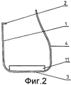
Фиг.2 - поперечное сечение крепежного элемента после деформирования стенки во время брошюрования множества листов;Figure 2 is a cross section of a fastener after deformation of the wall during the binding of multiple sheets;
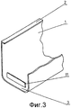
Фиг.3 - вид части крепежного элемента согласно примеру выполнения изобретения;Figure 3 is a view of a portion of a fastener according to an example embodiment of the invention;
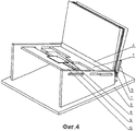
Фиг.4 - устройство для брошюрования множества листов крепежным элементом со стопкой листов, помещенной в крепежный элемент; и4 is a device for stitching multiple sheets of fastener with a stack of sheets placed in the fastener; and
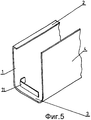
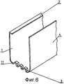
Фиг.5 и 6 - части крепежных элементов согласно примерам выполнения изобретения.5 and 6 are parts of fasteners according to exemplary embodiments of the invention.
Крепежный элемент по настоящему изобретению имеет форму канала, одна вертикальная стенка 1 которого отогнута в верхней части под углом, приближающимся к прямому, для образования по всей длине этой стенки поперечины 2, ширина которой значительно меньше размеров остальных стенок элемента. Горизонтальное основание 3 элемента через закругленные участки переходит в боковые стенки. Ширина основания 3 зависит от толщины стопки брошюруемых листов. Крепежный элемент оснащен упорами 11, прикрепленными к горизонтальному основанию 3 и/или к вертикальной боковой стенке 1 и/или 4 на незначительном расстоянии от обоих концов крепежного элемента и которые препятствуют сброшюрованной стопке смещаться внутри относительно обложки. Предпочтительно, вторая вертикальная стенка 4 имеет высоту, превышающую высоту первой вертикальной стенки 1.The fastening element of the present invention has the shape of a channel, one
Устройство по настоящему изобретению имеет в иллюстративном варианте неподвижное основание 5 L-образного сечения, ширина которого регулируется под размеры стопки брошюруемых листов. Предпочтительно, основание 5 расположено наклонно на горизонтальной подставке 6 так, чтобы эта часть обложки стопки бумаги в крепежном элементе, которая не будет деформирована, опиралась на длинную полку L-образного основания, а горизонтальное основание 3 крепежного элемента, опиралось на короткую полку L-образного основания. Таким образом, брошюруемые листы под собственным весом опираются на длинную полку L-образного основания 5 и не требуют дополнительной опоры. Деформирующий элемент 7 расположен на противоположной стороне от деформирующей кромки со скошенной кромкой 8, предназначенной для взаимодействия с клиновидным промежуточным элементом 9, который передает усилие, необходимое для деформирования стенки 4 крепежного элемента и принимаемое от приводного элемента 10. Взаимодействие приводного элемента 10, промежуточного элемента 9 и деформирующего элемента 7 предотвращает приложение чрезмерного усилия к стенке 4, изменяя направление воздействия части деформирующей силы на смещение промежуточного элемента 9 вдоль скошенной кромки 8 деформирующего элемента 7.The device of the present invention has, in an illustrative embodiment, a
Для брошюрования множества листов их вставляют в крепежный элемент так, чтобы их соединяемые кромки опирались на горизонтальное основание 3, крепежный элемент один или прикрепленный к обложке, помещают на основание 5 так, чтобы первая вертикальная стенка 1 крепежного элемента стабильно опиралась на гладкую стенку основания 5, и с противоположной стороны смещают деформирующий элемент 7 в сторону второй вертикальной стенки 4, прилагая усилие к подвижному элементу 10.To stitch many sheets, they are inserted into the fastener so that their joined edges rest on the
Claims (5)
Applications Claiming Priority (2)
| Application Number | Priority Date | Filing Date | Title |
|---|---|---|---|
| PL350812A PL193931B1 (en) | 2001-11-22 | 2001-11-22 | Stapling element for, method of and apparatus for binding together plurality of pages suing such stapling element |
| PLP350812 | 2001-11-22 |
Publications (2)
| Publication Number | Publication Date |
|---|---|
| RU2004118711A RU2004118711A (en) | 2005-03-10 |
| RU2301744C2 true RU2301744C2 (en) | 2007-06-27 |
Family
ID=20079578
Family Applications (1)
| Application Number | Title | Priority Date | Filing Date |
|---|---|---|---|
| RU2004118711/12A RU2301744C2 (en) | 2001-11-22 | 2002-11-21 | Fastening member, method for binding of a plurality sheets by means of fastening member and apparatus for binding of a plurality sheets by means of fastening member |
Country Status (10)
| Country | Link |
|---|---|
| EP (1) | EP1456037B9 (en) |
| AT (1) | ATE312724T1 (en) |
| AU (1) | AU2002366109A1 (en) |
| DE (1) | DE60208077T2 (en) |
| ES (1) | ES2254789T3 (en) |
| NO (1) | NO327524B1 (en) |
| PL (1) | PL193931B1 (en) |
| RU (1) | RU2301744C2 (en) |
| UA (1) | UA76255C2 (en) |
| WO (1) | WO2003043834A1 (en) |
Cited By (1)
| Publication number | Priority date | Publication date | Assignee | Title |
|---|---|---|---|---|
| RU2661707C2 (en) * | 2016-01-29 | 2018-07-19 | Опус Спулка З Ограничоно Одповедзяльносьцё | Element for tilting side wall of channel for fastening pages |
Families Citing this family (5)
| Publication number | Priority date | Publication date | Assignee | Title |
|---|---|---|---|---|
| US7798736B2 (en) | 2006-07-21 | 2010-09-21 | Hewlett-Packard Development Company, L.P. | Media binder arrangements |
| US7823927B2 (en) * | 2006-07-21 | 2010-11-02 | Hewlett-Packard Development Company, L.P. | Media binder systems with datum stops for registering physical media sheets |
| US7922207B2 (en) | 2006-09-18 | 2011-04-12 | Hewlett-Packard Development Company, L.P. | Activation and deactivation mechanisms for media binders |
| DE102006045289A1 (en) * | 2006-09-22 | 2008-04-03 | Esselte Leitz Gmbh & Co. Kg | Gutter for binding paper sheets |
| US7757358B2 (en) | 2007-03-02 | 2010-07-20 | Hewlett-Packard Development Company, L.P. | Sheet retention mechanisms for spring clamp binders |
Family Cites Families (5)
| Publication number | Priority date | Publication date | Assignee | Title |
|---|---|---|---|---|
| GB160177A (en) * | 1920-03-16 | 1922-05-25 | George Alfred Bennett | Improvements in renewable or loose leaf books |
| GB348577A (en) * | 1930-02-13 | 1931-05-13 | Perry & Co Ltd | A new or improved device for the positioning of folders, papers, and documents in loose leaf binders |
| DE2200387A1 (en) * | 1971-01-07 | 1972-07-20 | Morris Leslie Joe | Stapling device |
| FR2640201A1 (en) * | 1988-12-12 | 1990-06-15 | Gaudin Andre | Practical manual stationery binding method |
| DE19901479C2 (en) * | 1999-01-15 | 2000-11-09 | Eichner Organisation Gmbh & Co | Holder for sheet-like recording media |
-
2001
- 2001-11-22 PL PL350812A patent/PL193931B1/en not_active IP Right Cessation
-
2002
- 2002-11-21 WO PCT/PL2002/000093 patent/WO2003043834A1/en active Search and Examination
- 2002-11-21 AU AU2002366109A patent/AU2002366109A1/en not_active Abandoned
- 2002-11-21 DE DE60208077T patent/DE60208077T2/en not_active Expired - Lifetime
- 2002-11-21 EP EP02803579A patent/EP1456037B9/en not_active Expired - Lifetime
- 2002-11-21 RU RU2004118711/12A patent/RU2301744C2/en not_active IP Right Cessation
- 2002-11-21 UA UA20040604816A patent/UA76255C2/en unknown
- 2002-11-21 ES ES02803579T patent/ES2254789T3/en not_active Expired - Lifetime
- 2002-11-21 AT AT02803579T patent/ATE312724T1/en not_active IP Right Cessation
-
2004
- 2004-06-14 NO NO20042468A patent/NO327524B1/en not_active IP Right Cessation
Cited By (1)
| Publication number | Priority date | Publication date | Assignee | Title |
|---|---|---|---|---|
| RU2661707C2 (en) * | 2016-01-29 | 2018-07-19 | Опус Спулка З Ограничоно Одповедзяльносьцё | Element for tilting side wall of channel for fastening pages |
Also Published As
| Publication number | Publication date |
|---|---|
| ES2254789T3 (en) | 2006-06-16 |
| WO2003043834A1 (en) | 2003-05-30 |
| NO20042468L (en) | 2004-06-14 |
| DE60208077T2 (en) | 2006-08-17 |
| EP1456037B9 (en) | 2006-05-03 |
| EP1456037B1 (en) | 2005-12-14 |
| PL193931B1 (en) | 2007-04-30 |
| RU2004118711A (en) | 2005-03-10 |
| WO2003043834B1 (en) | 2003-10-23 |
| ATE312724T1 (en) | 2005-12-15 |
| EP1456037A1 (en) | 2004-09-15 |
| PL350812A1 (en) | 2003-06-02 |
| UA76255C2 (en) | 2006-07-17 |
| NO327524B1 (en) | 2009-08-03 |
| DE60208077D1 (en) | 2006-01-19 |
| AU2002366109A1 (en) | 2003-06-10 |
Similar Documents
| Publication | Publication Date | Title |
|---|---|---|
| US8167255B2 (en) | Hinge with elastic element and tab adapted in cardboard display stands for assembly, flattening and automatic set-up systems | |
| RU2301744C2 (en) | Fastening member, method for binding of a plurality sheets by means of fastening member and apparatus for binding of a plurality sheets by means of fastening member | |
| EP2281972A3 (en) | An equipment and a method of providing rectangular floor panels with a mechanical locking system | |
| CA2595372A1 (en) | Refillable notebook | |
| AU2009101115A4 (en) | A Continuously Adjustable Furring Channel Clip | |
| US7393171B2 (en) | Device and method of binding books | |
| NL9002550A (en) | WALL CONSTRUCTION WITH WALL PARTS ATTACHED BY BLIND BRACKETS TO STYLES AND / OR BEAMS. | |
| GB2145033A (en) | Binding sheets of paper or the like | |
| WO2005074748A1 (en) | Post coupler | |
| TW546206B (en) | Binder | |
| GB2292544A (en) | File | |
| KR20000053192A (en) | Shielded card holder for printed circuit boards | |
| US20040244239A1 (en) | Object holder | |
| WO1993009958A1 (en) | Improvements relating to comb binders | |
| KR200196427Y1 (en) | Book binding with twin spring | |
| GB2290257A (en) | Sheet binding | |
| US8500097B2 (en) | Flooring element locator including a substantially circular spacing member | |
| WO1993001422A1 (en) | Metal fixture for adjusting space | |
| FR2708581A1 (en) | Sorter for stapling sheets in compartments. | |
| KR200386581Y1 (en) | Assistant equipment for sheetbinding | |
| JP2504822Y2 (en) | Bookcase | |
| KR100584246B1 (en) | stapler bookbinder | |
| JPH0686948U (en) | Sample book binding | |
| JPH1120367A (en) | Forming mechanism of leg for binding member in binding apparatus | |
| JPH08175067A (en) | Filing implement |
Legal Events
| Date | Code | Title | Description |
|---|---|---|---|
| MM4A | The patent is invalid due to non-payment of fees |
Effective date: 20201122 |