RU2297597C2 - Electronic field device with sensor unit for capacitive measurement of level in reservoir - Google Patents
Electronic field device with sensor unit for capacitive measurement of level in reservoir Download PDFInfo
- Publication number
- RU2297597C2 RU2297597C2 RU2004121172/28A RU2004121172A RU2297597C2 RU 2297597 C2 RU2297597 C2 RU 2297597C2 RU 2004121172/28 A RU2004121172/28 A RU 2004121172/28A RU 2004121172 A RU2004121172 A RU 2004121172A RU 2297597 C2 RU2297597 C2 RU 2297597C2
- Authority
- RU
- Russia
- Prior art keywords
- measured
- microprocessor
- voltage
- sig
- signal
- Prior art date
Links
Images
Classifications
-
- G—PHYSICS
- G01—MEASURING; TESTING
- G01D—MEASURING NOT SPECIALLY ADAPTED FOR A SPECIFIC VARIABLE; ARRANGEMENTS FOR MEASURING TWO OR MORE VARIABLES NOT COVERED IN A SINGLE OTHER SUBCLASS; TARIFF METERING APPARATUS; MEASURING OR TESTING NOT OTHERWISE PROVIDED FOR
- G01D3/00—Indicating or recording apparatus with provision for the special purposes referred to in the subgroups
- G01D3/02—Indicating or recording apparatus with provision for the special purposes referred to in the subgroups with provision for altering or correcting the law of variation
-
- G—PHYSICS
- G01—MEASURING; TESTING
- G01F—MEASURING VOLUME, VOLUME FLOW, MASS FLOW OR LIQUID LEVEL; METERING BY VOLUME
- G01F23/00—Indicating or measuring liquid level or level of fluent solid material, e.g. indicating in terms of volume or indicating by means of an alarm
- G01F23/22—Indicating or measuring liquid level or level of fluent solid material, e.g. indicating in terms of volume or indicating by means of an alarm by measuring physical variables, other than linear dimensions, pressure or weight, dependent on the level to be measured, e.g. by difference of heat transfer of steam or water
- G01F23/26—Indicating or measuring liquid level or level of fluent solid material, e.g. indicating in terms of volume or indicating by means of an alarm by measuring physical variables, other than linear dimensions, pressure or weight, dependent on the level to be measured, e.g. by difference of heat transfer of steam or water by measuring variations of capacity or inductance of capacitors or inductors arising from the presence of liquid or fluent solid material in the electric or electromagnetic fields
- G01F23/263—Indicating or measuring liquid level or level of fluent solid material, e.g. indicating in terms of volume or indicating by means of an alarm by measuring physical variables, other than linear dimensions, pressure or weight, dependent on the level to be measured, e.g. by difference of heat transfer of steam or water by measuring variations of capacity or inductance of capacitors or inductors arising from the presence of liquid or fluent solid material in the electric or electromagnetic fields by measuring variations in capacitance of capacitors
- G01F23/266—Indicating or measuring liquid level or level of fluent solid material, e.g. indicating in terms of volume or indicating by means of an alarm by measuring physical variables, other than linear dimensions, pressure or weight, dependent on the level to be measured, e.g. by difference of heat transfer of steam or water by measuring variations of capacity or inductance of capacitors or inductors arising from the presence of liquid or fluent solid material in the electric or electromagnetic fields by measuring variations in capacitance of capacitors measuring circuits therefor
Landscapes
- Physics & Mathematics (AREA)
- Engineering & Computer Science (AREA)
- Power Engineering (AREA)
- General Physics & Mathematics (AREA)
- Electromagnetism (AREA)
- Thermal Sciences (AREA)
- Fluid Mechanics (AREA)
- Technology Law (AREA)
- Measurement Of Resistance Or Impedance (AREA)
- Measurement Of Levels Of Liquids Or Fluent Solid Materials (AREA)
Abstract
Description
Изобретение относится к электронному полевому прибору с сенсорным блоком для емкостных измерений уровня в резервуаре, согласно ограничительной части п.1 формулы.The invention relates to an electronic field device with a sensor unit for capacitive level measurements in the tank, according to the restrictive part of
Полевые приборы для емкостного измерения уровня известны уже много лет. При этом направленный в резервуар зонд и стенка резервуара образуют конденсатор. Емкость полученного таким образом конденсатора зависит от уровня и диэлектрической постоянной измеряемой среды.Field devices for capacitive level measurement have been known for many years. In this case, the probe directed to the tank and the tank wall form a capacitor. The capacitance of the capacitor thus obtained depends on the level and dielectric constant of the medium being measured.
Одной возможностью измерения этой емкости является так называемое измерение полного тока. При этом посредством традиционной выпрямительной схемы измеряют значение переменного тока, который при определенных частоте и напряжении течет через образованный зондом, средой и стенкой резервуара конденсатор. Полный ток зависит, правда, не только от емкости, но и от проводимости измеряемой среды, что на практике приводит к неточностям, поскольку проводимость прежде всего сыпучих продуктов зависит от различных факторов, таких, например, как температура и влажность воздуха.One possibility of measuring this capacitance is the so-called total current measurement. In this case, by means of a traditional rectifier circuit, the value of alternating current is measured, which at a certain frequency and voltage flows through a capacitor formed by the probe, medium and the wall of the tank. The total current depends, however, not only on the capacitance, but also on the conductivity of the medium being measured, which in practice leads to inaccuracies, since the conductivity of primarily bulk products depends on various factors, such as, for example, temperature and humidity.
Одним из методов подавления влияния параллельной проводимости является измерение при относительно высоких частотах. Поскольку протекающая через емкость доля (реактивная составляющая) полного тока увеличивается пропорционально частоте, тогда как вызванная проводимостью доля остается постоянной, при высоких частотах преобладает практически всегда емкостная доля. Измерение при высоких частотах (>100 кГц) приводит, однако, по опыту, к трудностям при длинных зондах с большими паразитными индуктивностями.One method of suppressing the effect of parallel conductivity is measurement at relatively high frequencies. Since the fraction (reactive component) of the total current flowing through the capacitance increases in proportion to the frequency, while the fraction caused by the conductivity remains constant, the capacitive fraction almost always prevails at high frequencies. Measurement at high frequencies (> 100 kHz) leads, however, from experience, to difficulties with long probes with large stray inductances.
Другой метод состоит в том, чтобы измерять не полный ток, а реактивный ток при угле сдвига фаз 90° между током и напряжением, что соответствует чисто емкостному измерению. Это может быть реализовано с помощью синхронной выпрямительной схемы. У этого способа недостаток, однако, состоит в том, что, например, в средах с низкой диэлектрической постоянной и высокой проводимостью, в которых с помощью измерения полного тока измерения возможны без проблем, из-за практически исчезающего реактивного тока возникают трудности. Кроме того, подобные традиционные синхронные выпрямительные схемы, по опыту, восприимчивы к электромагнитным помехам.Another method is to measure not the total current, but the reactive current at a phase angle of 90 ° between the current and voltage, which corresponds to a purely capacitive measurement. This can be realized using a synchronous rectifier circuit. This method has a drawback, however, in that, for example, in environments with a low dielectric constant and high conductivity, in which measurements can be made without problems by measuring the total current, difficulties arise due to the practically disappearing reactive current. In addition, such traditional synchronous rectifier circuits are, in experience, susceptible to electromagnetic interference.
В основе изобретения лежит задача создания электронного полевого прибора с сенсорным блоком для емкостных измерений уровня в резервуаре, который легко можно было бы приспособить к имеющимся полевым условиям и с помощью которого в зависимости от конкретного назначения применялся бы наиболее подходящий метод измерений.The basis of the invention is the task of creating an electronic field device with a sensor unit for capacitive level measurements in the tank, which could easily be adapted to existing field conditions and with which, depending on the specific purpose, the most suitable measurement method would be applied.
Эта задача решается согласно изобретению посредством признаков п.1 формулы. Зависимые пункты касаются предпочтительных выполнений и усовершенствований изобретения.This problem is solved according to the invention by the features of
Основная идея изобретения состоит в использовании микропроцессора для вырабатывания сигнала напряжения, для оценки измеряемого тока, для компенсации паразитных влияний и для вычисления определяемых величин устройства датчик/резервуар, причем соответствующие программы хранятся в блоке памяти. Для обработки микропроцессором аналоговый измеряемый ток преобразуют посредством аналого-цифрового преобразователя в цифровую форму. За счет использования микропроцессора простым образом можно выбирать и применять метод измерений, оптимальный для имеющихся полевых условий.The main idea of the invention is to use a microprocessor to generate a voltage signal, to evaluate the measured current, to compensate for spurious effects and to calculate the detected values of the sensor / tank device, and the corresponding programs are stored in the memory unit. For microprocessor processing, the measured analog current is converted into a digital form by means of an analog-to-digital converter. Through the use of a microprocessor in a simple way, you can choose and apply a measurement method that is optimal for existing field conditions.
К тому же за счет использования микропроцессора можно вырабатывать различные выходные сигналы, которые зависят от дальнейшего использования выходного сигнала или применяемого протокола передачи. Так, можно вырабатывать, например, сигнал 4-20 мА, сигнал 0-10 В, ЧИМ-сигнал (частотно-импульсно-модулированный сигнал), двоичный коммутирующий сигнал и т.д. Можно также вырабатывать и передавать несколько выходных сигналов (сигнал 4-20 мА, сигнал 0-10 В, ЧИМ-сигнал, двоичный коммутирующий сигнал и т.д.) для различных протоколов передачи или целей применения.In addition, through the use of a microprocessor, various output signals can be generated, which depend on the further use of the output signal or the transmission protocol used. So, it is possible to generate, for example, a 4-20 mA signal, a 0-10 V signal, a PFM signal (pulse frequency modulated signal), a binary switching signal, etc. It is also possible to generate and transmit several output signals (4-20 mA signal, 0-10 V signal, PFM signal, binary switching signal, etc.) for various transmission protocols or applications.
У одной формы выполнения изобретения микропроцессор выполняет для вырабатывания сигнала напряжения генераторную функцию, причем измеряемую частоту сигнала напряжения устанавливает микропроцессор.In one embodiment of the invention, the microprocessor performs a generator function to generate a voltage signal, and the microprocessor sets the measured frequency of the voltage signal.
Согласно одной предпочтительной форме выполнения микропроцессор выполняет для вырабатывания сигналов напряжения с разными частотами функцию переключения частот.According to one preferred embodiment, the microprocessor performs a frequency switching function to generate voltage signals with different frequencies.
Генераторная функция может быть реализована, например, путем деления частоты тактового сигнала микропроцессора, причем делителем частоты управляют в зависимости от желаемой измеряемой частоты сигнала напряжения посредством функции переключения частот.The generator function can be realized, for example, by dividing the frequency of the clock signal of the microprocessor, and the frequency divider is controlled depending on the desired measured frequency of the voltage signal through the frequency switching function.
За счет деления такта процессора сигнал напряжения может быть выработан практически с любой измеряемой частотой в пределах такта процессора. Переключение частот может быть реализовано, таким образом, без проблем с помощью программы. Это имеет, с одной стороны, преимущество того, что электронику можно приспособить к различным случаям применения, а, кроме того, за счет попеременного измерения при двух различных измеряемых частотах можно достичь простой компенсации параллельной проводимости.By dividing the processor clock, a voltage signal can be generated with virtually any measured frequency within the processor clock. Frequency switching can be implemented in this way without problems with the program. This has, on the one hand, the advantage that the electronics can be adapted to various applications, and, in addition, due to the alternate measurement at two different measured frequencies, it is possible to achieve a simple compensation of parallel conductivity.
Для вырабатывания синусоидального напряжения у одного усовершенствования изобретения предусмотрен фильтр нижних частот, который преобразует сигнал напряжения в синусоидальное напряжение. Можно также использовать для измерения любые произвольные формы сигналов с определенным содержанием высших гармоник.In order to generate a sinusoidal voltage, one refinement of the invention provides a low-pass filter that converts the voltage signal into a sinusoidal voltage. You can also use to measure any arbitrary waveforms with a certain content of higher harmonics.
Для вырабатывания синусоидальных напряжений с разными частотами фильтр нижних частот у одной предпочтительной формы выполнения изобретения располагает устанавливаемыми предельными частотами, причем актуальную предельную частоту фильтра нижних частот устанавливают посредством функции переключения частот в зависимости от установленной измеряемой частоты генератора для вырабатывания сигнала напряжения.To generate sinusoidal voltages with different frequencies, the low-pass filter at one preferred form of the invention has settable limit frequencies, the actual cut-off frequency of the low-pass filter being set by a frequency switching function depending on the set measured frequency of the generator to generate a voltage signal.
В соответствии с одним усовершенствованием изобретения измеряемый ток перед оценкой преобразуют посредством преобразователя ток/напряжение в пропорциональное измеряемому току измеряемое напряжение.In accordance with one refinement of the invention, the measured current is converted by means of a current / voltage converter into a measured voltage proportional to the measured current, before evaluation.
В соответствии с одним особенно предпочтительным усовершенствованием изобретения измеряемое напряжение выпрямляют выпрямителем и через аналого-цифровой преобразователь подают к микропроцессору для обработки.In accordance with one particularly preferred development of the invention, the measured voltage is rectified by a rectifier and fed through an analog-to-digital converter to a microprocessor for processing.
Выпрямитель включает в себя согласно одной форме выполнения зарядный конденсатор и может быть выполнен, например, в виде пикового выпрямителя или в виде синхронного выпрямителя.The rectifier includes, according to one embodiment, a charging capacitor and can be made, for example, in the form of a peak rectifier or in the form of a synchronous rectifier.
В первом методе измерений микропроцессор вычисляет значение измеряемого тока при определенном угле сдвига фаз в отношении сигнала напряжения, причем угол сдвига фаз может быть установлен микропроцессором.In the first measurement method, the microprocessor calculates the value of the measured current at a certain phase angle in relation to the voltage signal, and the phase angle can be set by the microprocessor.
Во втором методе измерений микропроцессор вырабатывает попеременно два сигнала напряжения с разными частотами и по соответствующим измеряемым токам вычисляет определенные величины устройства датчик/резервуар.In the second measurement method, the microprocessor alternately generates two voltage signals with different frequencies and calculates certain values of the sensor / tank device from the corresponding measured currents.
В соответствии с одной особенно предпочтительной формой выполнения изобретения микропроцессор вырабатывает необходимый угол сдвига фаз между сигналом напряжения и измеряемым током за счет выработанного им сдвига фаз между синхронизирующим сигналом и сигналом напряжения, причем синхронизирующий сигнал управляет синхронным выпрямителем.In accordance with one particularly preferred embodiment of the invention, the microprocessor generates the necessary phase angle between the voltage signal and the measured current due to the phase shift generated between the synchronizing signal and the voltage signal, the synchronizing signal controlling a synchronous rectifier.
Поскольку угол сдвига фаз, при котором измеряют ток через зонд, может быть выбран в широких пределах произвольно с помощью программных средств, можно осуществлять переключение между измерением чисто реактивного тока (емкостное измерение), измерением полного тока (измерение импеданса) и измерением чисто активного тока (измерение проводимости).Since the phase angle at which the current through the probe is measured can be arbitrarily selected over a wide range using software, it is possible to switch between measuring purely reactive current (capacitive measurement), measuring the total current (measuring impedance), and measuring purely active current ( conductivity measurement).
Поскольку синхронизирующий сигнал для синхронного выпрямления вырабатывают в микропроцессоре независимо и не выводят, как в традиционных синхронных выпрямительных схемах, из сигнала аналогового осциллятора, этот вид измерений менее восприимчив к электромагнитным помехам.Since the synchronization signal for synchronous rectification is independently generated in the microprocessor and is not derived, as in traditional synchronous rectification circuits, from the signal of an analog oscillator, this type of measurement is less susceptible to electromagnetic interference.
В соответствии с одной особенно предпочтительной формой выполнения изобретения микропроцессор в зависимости от определяемых величин и/или от полевых условий устанавливает измеряемую частоту сигнала напряжения и/или угол сдвига фаз для оценки измеряемого тока.In accordance with one particularly preferred embodiment of the invention, the microprocessor sets the measured frequency of the voltage signal and / or the phase angle to determine the measured current, depending on the values determined and / or on the field conditions.
Определяемыми величинами устройства датчик/резервуар могут быть, например, импеданс и/или емкость, и/или проводимость.The sensed values of the sensor / reservoir device may be, for example, impedance and / or capacitance and / or conductivity.
Полевые условия включают в себя, например, геометрию датчика и резервуара и/или вид среды в резервуаре, и/или возмущающие воздействия.Field conditions include, for example, the geometry of the sensor and the tank and / or the type of medium in the tank, and / or disturbances.
Микропроцессор выполняет к тому же дополнительные функции, такие как линеаризация и масштабирование измеренного сигнала, и вырабатывает выходной сигнал датчика.The microprocessor also performs additional functions, such as linearizing and scaling the measured signal, and generates an output signal from the sensor.
В соответствии с одной особенно предпочтительной формой выполнения изобретения измерение осуществляют не непрерывно, а в течение одного измерительного цикла вырабатывают и оценивают отдельные пакеты синусоидальных колебаний числом, например, 1000. Между отдельными пакетами синусоидальных колебаний имеются паузы, причем продолжительность пауз является переменной и устанавливается, например, генератором случайных чисел. За счет этого можно достичь повышенной невосприимчивости к электромагнитным воздействиям, поскольку между измерительным и паразитным сигналами не могут возникнуть постоянные интерференции.In accordance with one particularly preferred embodiment of the invention, the measurement is not continuous, but during one measurement cycle individual packets of sinusoidal oscillations are generated and evaluated, for example, 1000. There are pauses between individual packets of sinusoidal oscillations, the duration of the pauses being variable and set, for example random number generator. Due to this, it is possible to achieve increased immunity to electromagnetic influences, since constant interference cannot occur between the measuring and spurious signals.
В соответствии с одной особенно предпочтительной формой выполнения изобретения электронный полевой прибор посредством микропроцессора в паузах между измерительными циклами переключают в режим экономии энергии. В течение этих пауз через зонд также не течет ток. За счет этого расход тока можно снизить до доли расхода тока, обычного у емкостных датчиков. Это представляет особый интерес для применений устройств по NAMUR.In accordance with one particularly preferred embodiment of the invention, the electronic field device is switched into a power saving mode in the pauses between measurement cycles. During these pauses, no current also flows through the probe. Due to this, the current consumption can be reduced to a fraction of the current consumption typical of capacitive sensors. This is of particular interest for NAMUR device applications.
Изобретение более подробно поясняется с помощью прилагаемых чертежей, на которых изображено:The invention is explained in more detail using the accompanying drawings, which depict:
- фиг.1: принципиальная блок-схема электронного полевого прибора для первого метода измерений;- figure 1: schematic block diagram of an electronic field device for the first measurement method;
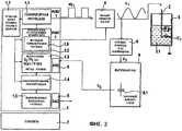
- фиг.2: принципиальная блок-схема электронного полевого прибора для второго метода измерений;- figure 2: schematic block diagram of an electronic field device for the second measurement method;
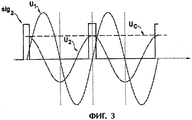
- фиг.3: зависимая от времени характеристика напряжений при чисто емкостной нагрузке;- figure 3: time-dependent voltage characteristic with a purely capacitive load;
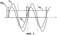
- фиг.4: зависимая от времени характеристика напряжений при смешанной емкостно-омической нагрузке.- figure 4: time-dependent voltage characteristic with a mixed capacitive-ohmic load.
Как видно из фиг.1 и 2, электронный полевой прибор включает в себя микропроцессор 1, датчик 2 для определения уровня среды 3.1 в резервуаре 3, фильтр 4, преобразователь 5 ток/напряжение, выпрямитель 6 и блок 7 памяти, причем выпрямитель 6 содержит конденсатор 6.1.As can be seen from figures 1 and 2, the electronic field device includes a
Как видно из фиг.1, микропроцессор 1 для осуществления первого метода измерений содержит функциональные блоки: генераторная функция 1.1, компенсация 1.2 возмущающих воздействий, вычислительная функция 1.3, масштабирование/линеаризация 1.4, вырабатывание выходного сигнала 1.5. Дополнительно имеется функциональный блок «установление измерительных циклов» 1.7, который определяет продолжительность измерительных циклов и продолжительность пауз между измерительными циклами. За счет этого посредством режима экономии энергии можно снизить расход тока. Дополнительно за счет изменения продолжительности пауз можно достичь повышенной невосприимчивости к электромагнитным воздействиям, поскольку между измерительным и паразитным сигналами не могут возникнуть постоянные интерференции. Посредством генераторной функции 1.1 микропроцессор 1 вырабатывает сигнал sig1 напряжения с измеряемой частотой f, который передается через PORT 1 и за счет последующего отфильтровывания нижних частот фильтром 4 преобразуется в синусоидальное напряжение U1. Генераторная функция 1.1 реализована при этом в виде делителя частоты или посредством встроенного в микропроцессор таймера, так что сигнал напряжения вырабатывается из тактового сигнала микропроцессора.As can be seen from figure 1, the
Для компенсации 1.2 возмущающих воздействий микропроцессор 1 выполняет функциональный блок «вырабатывание синхронизирующего сигнала» 1.8 и вырабатывает синхронизирующий сигнал sig2, который имеет устанавливаемый угол сдвига фаз по отношению к сигналу sig1 напряжения. В изображенном примере выполнения синхронизирующий сигнал sig2 используют для управления выпрямителем 6 и передают через PORT 2. В зависимости от угла сдвига фаз, установленного между сигналом sig1 напряжения и синхронизирующим сигналом sig2, можно осуществлять измерение чисто реактивного тока, т.е. устанавливают угол сдвига фаз 0°, или измерение чисто активного тока, т.е. устанавливают угол сдвига фаз 90°. Таким образом, можно устранить имеющиеся возмущающие воздействия, такие как омические сопротивления, у емкостного измерительного зонда или емкости у проводящего измерительного зонда.To compensate for 1.2 disturbing influences,
Преобразователь 5 ток/напряжение преобразует вызванный сигналом U1 напряжения ток через сенсорный блок 2 в пропорциональный сигнал U2 напряжения.The current /
Выпрямитель 6 выполнен для первого метода измерений в виде синхронного выпрямителя и содержит дополнительно к зарядному конденсатору 6.1 управляемый выключатель 6.2, выполненный, например, в виде МОП-транзистора. Выключатель 6.2 управляется синхронизирующим сигналом sig2. При приложении высокого уровня синхронизирующим сигналом sig2 зарядный конденсатор 6.1 заряжается через выключатель 6.2 до данного моментального значения напряжения U2. При угле сдвига фаз 0°, установленном между сигналом sig1 напряжения и синхронизирующим сигналом sig2, выходное напряжение UC выпрямителя 6 соответствует реактивной составляющей протекающего через сенсорный блок 2 тока. Выходное напряжение UC подают через аналого-цифровой преобразователь 8 к микропроцессору 1, причем аналого-цифровой преобразователь 8 в изображенном примере выполнения встроен в микропроцессор 1.Rectifier 6 is made for the first measurement method in the form of a synchronous rectifier and contains, in addition to the charging capacitor 6.1, a controllable switch 6.2, made, for example, in the form of a MOS transistor. Switch 6.2 is controlled by the sig 2 clock signal. When a high level is applied by the synchronizing signal sig 2, the charging capacitor 6.1 is charged through the switch 6.2 to a given instantaneous voltage value U 2 . With a phase angle of 0 ° set between the voltage signal sig 1 and the clock signal sig 2 , the output voltage U C of the rectifier 6 corresponds to the reactive component of the current flowing through the
С помощью вычислительной функции 1.3 микропроцессор 1 вычисляет по выпрямленному напряжению UC, измеренному на зарядном конденсаторе 6.1, определяемые величины устройства датчик/резервуар, например емкость C1 и/или параллельное сопротивление R1.Using the computational function 1.3, the
В качестве дополнительной функции микропроцессор 1 выполняет масштабирование и линеаризацию 1.4 вычисленных значений.As an additional function,
При вырабатывании выходного сигнала 1.5 микропроцессор 1 вырабатывает желаемый выходной сигнал, который зависит от дальнейшего использования выходного сигнала или от используемого протокола передачи. Так, например, может быть выработан сигнал 4-20 мА, сигнал 0-10 В, ЧИМ-сигнал (частотно-импульсно-модулированный сигнал), двоичный коммутирующий сигнал и т.д. Можно также вырабатывать и передавать несколько выходных сигналов (сигнал 4-20 мА, сигнал 0-10 В, ЧИМ-сигнал, двоичный коммутирующий сигнал и т.д.) для различных протоколов передачи или целей применения. Для вырабатывания определенных стандартных выходных сигналов в микропроцессор 1 может быть встроен цифроаналоговый преобразователь 9.When generating the output signal 1.5, the
На фиг.3 в зависимости от времени изображены сигналы U1, U2 и sig2. Если принять чисто емкостное поведение устройства датчик/среда/резервуар с емкостью C1, то напряжение U2, пропорциональное протекающему через сенсорный блок 2 току, сдвинуто по фазе на 90° относительно напряжения U1. Зарядный конденсатор 6.1 в течение определяемого сигналом sig2 промежутка времени заряжается до пикового значения U2 в этот промежуток времени, т.е. до напряжения UC. Установленный угол сдвига фаз между сигналом sig1 напряжения и синхронизирующим сигналом sig2, составляет при этом 0°.Figure 3, depending on the time depicted signals U 1 , U 2 and sig 2 . If we accept the purely capacitive behavior of the sensor / medium / reservoir device with a capacitance C 1 , then the voltage U 2 proportional to the current flowing through the
На фиг.4 в зависимости от времени также изображены сигналы U1, U2 и sig2. Однако дополнительно к емкости C1 учитывают параллельное сопротивление R1 среды 3.1. Как видно из диаграммы, возрастает значение тока через сенсорный блок 2 и, тем самым, значение представляющего ток напряжения U2. Угол сдвига фаз между U1 и U2 составляет менее 90°. При этом значение напряжения U2 в определяемый сигналом sig2 промежуток времени изменяется по сравнению с изображенным на фиг.3 случаем лишь незначительно, и, тем самым, зарядный конденсатор 6.1 заряжается до того же напряжения UC, что и при чисто емкостной нагрузке. Установленный угол сдвига фаз между сигналом sig1 напряжения и синхронизирующим сигналом sig2, составляет также 0°, и осуществляется измерение чисто реактивного тока.Figure 4 also depicts the signals U 1 , U 2 and sig 2 as a function of time. However, in addition to the capacitance C 1, the parallel resistance R 1 of the medium 3.1 is taken into account. As can be seen from the diagram, the value of the current through the
Таким образом, можно измерять емкость C1 независимо от имеющегося параллельного сопротивления R1. Поскольку многие проблемы вызваны при емкостных измерениях проводимостью и колебаниями влажности, которые изменяют проводимость измеряемой среды 3.1, это дает заметные преимущества.Thus, it is possible to measure the capacitance C 1 regardless of the available parallel resistance R 1 . Since many problems are caused by capacitive measurements of conductivity and humidity fluctuations, which change the conductivity of the medium being measured 3.1, this gives noticeable advantages.
Для осуществления измерения полного тока выключатель 6.2 в выпрямителе 6 постоянно замкнут, т.е. синхронизирующий сигнал sig2 является постоянным высоким сигналом, или используют простой пиковый выпрямитель.To measure the total current, the switch 6.2 in the rectifier 6 is constantly closed, i.e. The sig 2 clock signal is a constant high signal, or use a simple peak rectifier.
Как видно из фиг.2, микропроцессор 1 для осуществления второго метода измерений также содержит функциональные блоки генераторная функция 1.1, компенсация 1.2 возмущающих воздействий, вычислительная функция 1.3, масштабирование/линеаризация 1.4, вырабатывание выходного сигнала 1.5. Дополнительно имеется функциональный блок «установление измерительных циклов» 1.7, который определяет продолжительность измерительных циклов и продолжительность пауз между измерительными циклами. За счет этого посредством режима экономии энергии можно снизить расход тока. Дополнительно за счет изменения продолжительности пауз можно достичь повышенной невосприимчивости к электромагнитным воздействиям, поскольку между измерительным и паразитным сигналами не могут возникнуть постоянные интерференции.As can be seen from figure 2, the
Компенсация 1.2 возмущающих воздействий включает в себя, однако, во втором методе измерений частотный переключатель 1.6, который определяет измеряемую частоту f выработанного генераторной функцией 1.1 сигнала sig1 напряжения. Для компенсации 1.2 возмущающих воздействий сигнал sig1 напряжения с заданными интервалами времени попеременно с частотами f1 и f2 передают через PORT 1. За счет последующего отфильтровывания нижних частот сигнал sig1 напряжения преобразуют в синусоидальное измеряемое напряжение U1(f1/f2), причем предельную частоту фильтра 4 устанавливают в соответствии с заданным за счет вырабатывания сигнала интервала времени, подходящей для частот f1 и f2. Установление предельных частот фильтра 4 происходит посредством выработанного частотным переключателем 1.6 управляющего сигнала, передаваемого через PORT 3. За счет этого для каждой частоты f1 и f2 достигается оптимальное преобразование прямоугольник/синус.Compensation 1.2 of disturbances includes, however, in the second measurement method, a frequency switch 1.6, which determines the measured frequency f generated by the generator function 1.1 of the voltage signal sig 1 . To compensate for 1.2 disturbances, the voltage signal sig 1 is transmitted alternately with frequencies f 1 and f 2 through
Преобразователь 5 ток/напряжение преобразует вызванный сигналом U1(f1/f2) напряжения ток через сенсорный блок 2 в пропорциональный сигнал U2 напряжения.The current /
Выпрямитель 6 включает в себя зарядный конденсатор 6.1 и вырабатывает пропорциональное U2 постоянное напряжение UC и может быть выполнен в виде традиционного пикового выпрямителя или синхронного выпрямителя, как это описано со ссылкой на фиг.1.Rectifier 6 includes a charging capacitor 6.1 and generates a constant voltage U C proportional to U 2 and can be made in the form of a traditional peak rectifier or synchronous rectifier, as described with reference to FIG. 1.
Выходные напряжения UC(f1) и UC(f2) зарядного конденсатора 6.1 подают через аналого-цифровой преобразователь к микропроцессору 1, причем аналого-цифровой преобразователь в изображенном примере выполнения встроен в микропроцессор 1.The output voltages U C (f1) and U C (f2) of the charging capacitor 6.1 are fed through an analog-to-digital converter to
С помощью вычислительной функции 1.3 микропроцессор 1 вычисляет по выпрямленным напряжениям UC(f1) и UC(f2), измеренным на зарядном конденсаторе 6.1, определяемые величины устройства датчик/резервуар, например емкость C1 и/или параллельное сопротивление R1. Вычисление значений C1 и R1 по напряжениям UC(f1) и UC(f2) происходит следующим образом.Using the computational function 1.3, the
Весь протекающий через сенсорный блок 2 полный ток определяется по формулеThe total current flowing through the
![]()
![]()
причем протекающий через конденсатор ток IC1 зависит от частоты:and the current I C1 flowing through the capacitor depends on the frequency:
![]()
![]()
Если измерения происходят при двух разных частотах f1 и f2, то справедливо:If the measurements occur at two different frequencies f 1 and f 2 , then it is true:
![]()
![]()
![]()
![]()
причем токи IS(f1) и IS(f2) за счет преобразования ток/напряжение и выпрямления пропорциональны U2(f1) и U2(f2) и, тем самым, известны. Следовательно, благодаря уравнениям [3] и [4] в распоряжении имеются два уравнения с двумя неизвестными, по которым можно вычислить C1 и R1.moreover, the currents I S (f1) and IS (f2) due to the current / voltage conversion and rectification are proportional to U 2 (f1) and U 2 (f2) and, therefore, are known. Therefore, thanks to equations [3] and [4], there are two equations with two unknowns that can be used to calculate C 1 and R 1 .
Таким образом, можно измерить емкость C1 независимо от параллельного сопротивления R1. Поскольку многие проблемы при емкостных измерениях вызваны проводимостью и колебаниями влажности, которые изменяют проводимость измеряемой среды 3.1, это дает заметные преимущества.Thus, it is possible to measure the capacitance C 1 regardless of the parallel resistance R 1 . Since many problems with capacitive measurements are caused by conductivity and humidity fluctuations, which change the conductivity of the medium being measured 3.1, this gives noticeable advantages.
Компенсация 1.2 возмущающих воздействий происходит, тем самым, за счет вырабатывания сигналов напряжения с разными частотами и за счет устранения соответствующего возмущающего воздействия при вычислении.Compensation of 1.2 disturbances occurs, thereby, due to the generation of voltage signals with different frequencies and due to the elimination of the corresponding disturbance in the calculation.
Масштабирование и линеаризация 1.4 измеренных и вычисленных значений, а также вырабатывание и передача желаемого выходного сигнала 1.5 происходят аналогично рассуждениям со ссылкой на фиг.1.The scaling and linearization of 1.4 measured and calculated values, as well as the generation and transmission of the desired output signal 1.5 occur similarly to the reasoning with reference to figure 1.
Особенно предпочтительный электронный полевой прибор комбинирует в себе оба метода измерений за счет того, что функциональные блоки для первого метода измерений и функциональные блоки для второго метода измерений реализованы в микропроцессоре 1. Выбор осуществляемого метода измерений и ввод необходимых параметров (частота, сдвиг по фазе) производится тогда пользователем в зависимости от устройства датчик/резервуар и измеряемой среды 3.1 и может быть осуществлен путем соответствующего диалога при вводе через средства ввода (не показаны). Выбор может осуществляться также из пункта управления через соответствующие коммуникационные соединения.A particularly preferred electronic field device combines both measurement methods due to the fact that the functional blocks for the first measurement method and the functional blocks for the second measurement method are implemented in
Кроме того, необходимые параметры (частота, сдвиг по фазе) и установки можно изменять посредством сменных блоков памяти.In addition, the necessary parameters (frequency, phase shift) and settings can be changed using removable memory blocks.
Claims (13)
Applications Claiming Priority (2)
| Application Number | Priority Date | Filing Date | Title |
|---|---|---|---|
| DE10161069.6 | 2001-12-12 | ||
| DE10161069A DE10161069A1 (en) | 2001-12-12 | 2001-12-12 | Field device electronics with a sensor unit for capacitive level measurements in a container |
Publications (2)
| Publication Number | Publication Date |
|---|---|
| RU2004121172A RU2004121172A (en) | 2005-05-27 |
| RU2297597C2 true RU2297597C2 (en) | 2007-04-20 |
Family
ID=7708955
Family Applications (1)
| Application Number | Title | Priority Date | Filing Date |
|---|---|---|---|
| RU2004121172/28A RU2297597C2 (en) | 2001-12-12 | 2002-11-30 | Electronic field device with sensor unit for capacitive measurement of level in reservoir |
Country Status (8)
| Country | Link |
|---|---|
| US (1) | US7415366B2 (en) |
| EP (1) | EP1454115A1 (en) |
| JP (1) | JP2005512078A (en) |
| CN (1) | CN1293365C (en) |
| AU (1) | AU2002366541A1 (en) |
| DE (1) | DE10161069A1 (en) |
| RU (1) | RU2297597C2 (en) |
| WO (1) | WO2003050480A1 (en) |
Cited By (1)
| Publication number | Priority date | Publication date | Assignee | Title |
|---|---|---|---|---|
| RU2743069C1 (en) * | 2017-11-17 | 2021-02-15 | Бедиа Моторентехник Гмбх Унд Ко. Кг | Device and method for capacitive measurement of filling medium filling level |
Families Citing this family (40)
| Publication number | Priority date | Publication date | Assignee | Title |
|---|---|---|---|---|
| DE10322279A1 (en) * | 2003-05-16 | 2004-12-02 | Endress + Hauser Gmbh + Co. Kg | Capacitive level measurement |
| US7134330B2 (en) | 2003-05-16 | 2006-11-14 | Endress + Hauser Gmbh + Co. Kg | Capacitive fill level meter |
| DE102004008125A1 (en) * | 2004-02-18 | 2005-09-01 | Endress + Hauser Gmbh + Co. Kg | Method and device for capacitive level determination |
| DE102004010096A1 (en) * | 2004-02-27 | 2005-09-15 | Endress + Hauser Gmbh + Co. Kg | Method for operating a field device of automation technology |
| US8538560B2 (en) * | 2004-04-29 | 2013-09-17 | Rosemount Inc. | Wireless power and communication unit for process field devices |
| US8145180B2 (en) * | 2004-05-21 | 2012-03-27 | Rosemount Inc. | Power generation for process devices |
| US8787848B2 (en) * | 2004-06-28 | 2014-07-22 | Rosemount Inc. | RF adapter for field device with low voltage intrinsic safety clamping |
| US8160535B2 (en) * | 2004-06-28 | 2012-04-17 | Rosemount Inc. | RF adapter for field device |
| DE102004047413A1 (en) * | 2004-09-28 | 2006-03-30 | Endress + Hauser Gmbh + Co. Kg | Production-side adjustment of a measuring device for capacitive level measurement and corresponding measuring device |
| DE102005051794A1 (en) * | 2005-10-27 | 2007-05-03 | Endress + Hauser Gmbh + Co. Kg | Device for the capacitive determination and / or monitoring of the level of a medium |
| WO2007122214A1 (en) * | 2006-04-24 | 2007-11-01 | Wika Alexander Wiegand Gmbh & Co. Kg | Measuring instrument in two-conductor technology |
| DE102006020342A1 (en) * | 2006-04-28 | 2007-10-31 | Endress + Hauser Gmbh + Co. Kg | Measuring device for determining and/or monitoring e.g. fill level, of e.g. fluid, has microprocessor executing basic functions in inactive state and controlling sensor units in active state, and migrated from inactive into active states |
| DE102006028006A1 (en) * | 2006-06-14 | 2007-12-20 | Siemens Ag | Field device and method for processing at least one measured variable in a field device |
| DE102006043809A1 (en) * | 2006-09-13 | 2008-03-27 | Endress + Hauser Gmbh + Co. Kg | Device for determining and / or monitoring a process variable |
| DE602006010567D1 (en) * | 2006-10-20 | 2009-12-31 | Rancilio Macchine Caffe | Device for regulating the liquid level of a cooking vessel of a coffee machine |
| DE102007061573A1 (en) * | 2007-12-18 | 2009-06-25 | Endress + Hauser Gmbh + Co. Kg | Device for determining and / or monitoring at least one level of at least one medium in a container according to a travel time measurement method and / or a capacitive measurement method |
| DE102008022370A1 (en) | 2008-05-06 | 2009-11-12 | Endress + Hauser Gmbh + Co. Kg | Method for determining reference values for measured values of a capacitance to be measured with a capacitive measuring device |
| US8049361B2 (en) * | 2008-06-17 | 2011-11-01 | Rosemount Inc. | RF adapter for field device with loop current bypass |
| EP2310918B1 (en) * | 2008-06-17 | 2014-10-08 | Rosemount, Inc. | Rf adapter for field device with variable voltage drop |
| US8929948B2 (en) * | 2008-06-17 | 2015-01-06 | Rosemount Inc. | Wireless communication adapter for field devices |
| US8694060B2 (en) * | 2008-06-17 | 2014-04-08 | Rosemount Inc. | Form factor and electromagnetic interference protection for process device wireless adapters |
| DE102008049623A1 (en) | 2008-09-30 | 2010-04-01 | Endress + Hauser Gmbh + Co. Kg | Method for manufacturing a capacitive measuring device |
| EP2219013B1 (en) * | 2009-02-13 | 2019-04-10 | VEGA Grieshaber KG | Energy production device for producing and simultaneously monitoring measured current |
| US8281655B2 (en) * | 2009-04-03 | 2012-10-09 | Eaton Corporation | Fuel gauging system utilizing a digital fuel gauging probe |
| US20100318007A1 (en) * | 2009-06-10 | 2010-12-16 | O'brien Donald J | Electromechanical tactile stimulation devices and methods |
| US9674976B2 (en) | 2009-06-16 | 2017-06-06 | Rosemount Inc. | Wireless process communication adapter with improved encapsulation |
| US8626087B2 (en) * | 2009-06-16 | 2014-01-07 | Rosemount Inc. | Wire harness for field devices used in a hazardous locations |
| DE102010038732B4 (en) | 2010-07-30 | 2023-07-27 | Endress+Hauser SE+Co. KG | Device and method for securing the attachment of a tube, arranged coaxially around a measuring probe, of a measuring probe unit of a fill level measuring device to a process connection element |
| US10761524B2 (en) | 2010-08-12 | 2020-09-01 | Rosemount Inc. | Wireless adapter with process diagnostics |
| DE102011004807A1 (en) | 2011-02-28 | 2012-08-30 | Endress + Hauser Gmbh + Co. Kg | probe unit |
| US9907908B2 (en) | 2011-03-08 | 2018-03-06 | Baxter International Inc. | Non-invasive radio frequency medical fluid level and volume detection system and method |
| US9310794B2 (en) | 2011-10-27 | 2016-04-12 | Rosemount Inc. | Power supply for industrial process field device |
| DE102013104781A1 (en) * | 2013-05-08 | 2014-11-13 | Endress + Hauser Gmbh + Co. Kg | Method for monitoring at least one media-specific property of a medium |
| DE102013107904A1 (en) | 2013-07-24 | 2015-01-29 | Endress + Hauser Flowtec Ag | Measuring device with switchable measuring and operating electronics for the transmission of a measuring signal |
| DE102014107927A1 (en) * | 2014-06-05 | 2015-12-17 | Endress + Hauser Gmbh + Co. Kg | Method and device for monitoring the level of a medium in a container |
| CN108204845B (en) * | 2016-12-19 | 2019-11-29 | 桓达科技股份有限公司 | Sensing device and substance method for sensing |
| US10422684B2 (en) * | 2017-05-30 | 2019-09-24 | Rosemount Tank Radar Ab | Field device with second auxiliary interface |
| CN108548585B (en) * | 2018-05-11 | 2020-01-31 | 广东美的厨房电器制造有限公司 | Water level measuring device and method for water box and steam stove |
| DE102019126381A1 (en) | 2019-09-30 | 2021-04-01 | Endress+Hauser SE+Co. KG | Hygienic adapter for field device |
| DE102021123443A1 (en) | 2021-09-10 | 2023-03-16 | Endress+Hauser Conducta Gmbh+Co. Kg | Method for determining a conductivity value |
Family Cites Families (15)
| Publication number | Priority date | Publication date | Assignee | Title |
|---|---|---|---|---|
| US3786349A (en) * | 1973-05-03 | 1974-01-15 | Northern Electric Co | Electrical reactance and loss measurement apparatus and method |
| US4451894A (en) * | 1980-05-14 | 1984-05-29 | Honeywell Inc. | Liquid gaging system multiplexing |
| DE3643389A1 (en) * | 1986-12-19 | 1988-07-07 | Duerrwaechter E Dr Doduco | METHOD FOR GENERATING AN ELECTRIC SINUS SIGNAL WITH VARIABLE FREQUENCY |
| DE3812687A1 (en) * | 1988-04-16 | 1989-10-26 | Duerrwaechter E Dr Doduco | CAPACITIVE SENSOR FOR DETERMINING THE LEVEL OF A LIQUID IN A CONTAINER |
| CA2032384C (en) * | 1989-12-18 | 2000-06-20 | Drexelbrook Controls, Inc. | Remote instrument testing system |
| WO1993020409A1 (en) | 1992-04-02 | 1993-10-14 | Micro-Epsilon Messtechnik Gmbh & Co. Kg | Sensor-drive and signal-processing method______________________ |
| US5406843A (en) * | 1993-10-27 | 1995-04-18 | Kdi Corporation, Inc. | Digital liquid level sensing apparatus |
| CN1088679A (en) * | 1993-11-03 | 1994-06-29 | 唐山钢铁(集团)公司 | Liquid level checking method for melted steel container heated by plasma |
| DE19757190A1 (en) * | 1997-12-22 | 1999-06-24 | Abb Research Ltd | Capacitive level sensor with integrated dirt film detection |
| DE59914913D1 (en) * | 1999-10-07 | 2009-01-08 | Endress Hauser Gmbh Co | Method and device for functional testing of a limit switch |
| EP1093039B1 (en) * | 1999-10-15 | 2003-11-26 | Endress + Hauser Flowtec AG | Programmable field mounted sensor |
| EP1108984B1 (en) * | 1999-10-18 | 2019-08-14 | Endress + Hauser Flowtec AG | Programmable mobile apparatus |
| US6854055B1 (en) * | 1999-10-18 | 2005-02-08 | Endress + Hauser Flowtec Ag | Method and system for switching active configuration memory during on-line operation of programmable field mounted device |
| DE19954186A1 (en) * | 1999-11-11 | 2001-05-17 | Endress Hauser Gmbh Co | Device and method for transmitting data between a sensor and an evaluation unit |
| DE10007188A1 (en) * | 2000-02-17 | 2001-08-23 | Endress Hauser Gmbh Co | Device for determining the level of a medium in a container |
-
2001
- 2001-12-12 DE DE10161069A patent/DE10161069A1/en not_active Withdrawn
-
2002
- 2002-11-30 AU AU2002366541A patent/AU2002366541A1/en not_active Abandoned
- 2002-11-30 WO PCT/EP2002/013537 patent/WO2003050480A1/en active Application Filing
- 2002-11-30 RU RU2004121172/28A patent/RU2297597C2/en not_active IP Right Cessation
- 2002-11-30 EP EP02804576A patent/EP1454115A1/en not_active Withdrawn
- 2002-11-30 US US10/497,543 patent/US7415366B2/en not_active Expired - Fee Related
- 2002-11-30 JP JP2003551486A patent/JP2005512078A/en active Pending
- 2002-11-30 CN CNB028246160A patent/CN1293365C/en not_active Expired - Fee Related
Cited By (1)
| Publication number | Priority date | Publication date | Assignee | Title |
|---|---|---|---|---|
| RU2743069C1 (en) * | 2017-11-17 | 2021-02-15 | Бедиа Моторентехник Гмбх Унд Ко. Кг | Device and method for capacitive measurement of filling medium filling level |
Also Published As
| Publication number | Publication date |
|---|---|
| CN1293365C (en) | 2007-01-03 |
| CN1602409A (en) | 2005-03-30 |
| US20070055463A1 (en) | 2007-03-08 |
| EP1454115A1 (en) | 2004-09-08 |
| WO2003050480A1 (en) | 2003-06-19 |
| RU2004121172A (en) | 2005-05-27 |
| DE10161069A1 (en) | 2003-06-18 |
| US7415366B2 (en) | 2008-08-19 |
| AU2002366541A1 (en) | 2003-06-23 |
| JP2005512078A (en) | 2005-04-28 |
Similar Documents
| Publication | Publication Date | Title |
|---|---|---|
| RU2297597C2 (en) | Electronic field device with sensor unit for capacitive measurement of level in reservoir | |
| RU2324286C1 (en) | Device for analog-to-digital conversion of measured voltage | |
| US4182983A (en) | Electronic AC electric energy measuring circuit | |
| US9423438B2 (en) | Dielectric constant measurement circuit and dielectric constant measurement method | |
| US4409543A (en) | Impedance meter | |
| JPS6025745B2 (en) | Power measurement method | |
| US6259259B1 (en) | Method and apparatus for automatically adjusting the measurement range of admittance level sensors | |
| EP0491852A4 (en) | Conversion circuit for an electromagnetic flow transmitter | |
| FI67961C (en) | PULSBREDD-PULSHOEJD-MULTIPLIKATOR I EN STATISK KWH-MAETARE | |
| US7134330B2 (en) | Capacitive fill level meter | |
| JPH09243683A (en) | Method and device for measurement of resistivity, electric conductivity and/or permittivity | |
| US10101190B2 (en) | Field device electronics for a conductive limit-level switch | |
| JP2002090401A (en) | Capacitance sensor circuit | |
| KR900008302B1 (en) | Power factor measuring circuit and method of power meter | |
| US7456700B2 (en) | Variable loop gain oscillator system | |
| RU215007U1 (en) | ACTIVE POWER TO DC VOLTAGE CONVERTER | |
| JP2589817Y2 (en) | LCR tester | |
| GB2093292A (en) | Apparatus and methods for analogue-to-digital conversion and for deriving in-phase and quadrature components of voltage and current in an impedance | |
| RU2120623C1 (en) | Capacitance proximate moisture meter | |
| RU91438U1 (en) | DEVICE FOR MEASURING REACTIVE RESISTANCE | |
| JP3316121B2 (en) | Reactive energy meter | |
| SU702317A1 (en) | Digital device for measuring rlc-parameters | |
| RU2103696C1 (en) | Method of measurement of quantity of dc electric energy | |
| SU1756834A1 (en) | Two-element two-terminal network parameter uniwersal meter | |
| GB2215474A (en) | Measuring the peak level of oscillating signals |
Legal Events
| Date | Code | Title | Description |
|---|---|---|---|
| MM4A | The patent is invalid due to non-payment of fees |
Effective date: 20111201 |