RU2294529C2 - Device for correcting errors in polynomial system of residue classes with usage of pseudo-orthogonal polynomials - Google Patents
Device for correcting errors in polynomial system of residue classes with usage of pseudo-orthogonal polynomials Download PDFInfo
- Publication number
- RU2294529C2 RU2294529C2 RU2005113806/09A RU2005113806A RU2294529C2 RU 2294529 C2 RU2294529 C2 RU 2294529C2 RU 2005113806/09 A RU2005113806/09 A RU 2005113806/09A RU 2005113806 A RU2005113806 A RU 2005113806A RU 2294529 C2 RU2294529 C2 RU 2294529C2
- Authority
- RU
- Russia
- Prior art keywords
- layer
- neurons
- inputs
- outputs
- neuron
- Prior art date
Links
Images

Landscapes
- Error Detection And Correction (AREA)
- Detection And Correction Of Errors (AREA)
Abstract
Description
Устройство относится к области вычислительной техники, в частности может быть использовано как для контроля и исправления ошибки при передаче информации, так и при проведении арифметических операций в расширенных полях Галуа GF(2v).The device relates to the field of computer technology, in particular, it can be used both to control and correct errors in the transmission of information, and during arithmetic operations in the extended Galois fields GF (2 v ).
Известно устройство для обнаружения и исправления ошибок (СССР №714399, 08.02.1980, G 06 F 11/08), содержащее регистр, два блока модульной свертки, предназначенных для вычисления остатков числа по контрольным основаниям, два модульных сумматора, предназначенных для вычисления синдрома ошибки по первому и второму контрольному основаниям, блок памяти, предназначенный для хранения констант, третий сумматор, предназначенный для получения исправленного числа путем суммирования ошибочного числа с константой ошибки.A device for detecting and correcting errors (USSR No. 714399, 02/08/1980, G 06
Недостатком устройства является низкое быстродействие вследствие отдельного последовательного применения блоков модульной свертки, предназначенных для вычисления остатков числа по контрольным основаниям и сумматоров, для вычисления синдромов ошибки по первому и второму контрольным основаниям.The disadvantage of this device is the low speed due to the separate sequential use of modular convolution blocks designed to calculate the remainder of the number on the control bases and adders, to calculate the error syndromes on the first and second control bases.
Техническим результатом, достигнутым при осуществлении заявленного изобретения, является повышение скорости обнаружения и коррекции ошибок.The technical result achieved by the implementation of the claimed invention is to increase the speed of detection and correction of errors.
Указанный технический результат достигается за счет применения полиномиальной системы классов вычетов (ПСКВ), в которой в качестве основания системы используется минимальные многочлены pi(z), i=1, 2, ..., k+r, определенные в расширенных полях Галуа GF(2v) и нейросетевых технологий, а также применения псевдоортогональных полиномов, определяемых в данной ПСКВ.The indicated technical result is achieved through the use of a polynomial system of residue classes (PSKV), in which the minimum polynomials p i (z), i = 1, 2, ..., k + r defined in the extended Galois fields GF are used as the base of the system (2 v ) and neural network technologies, as well as the use of pseudo-orthogonal polynomials defined in this PSKV.
Особенность ПСКВ состоит в том, что независимость обработки информации по основаниям ПСКВ позволяет не только повысить скорость и точность обработки, но также и обеспечить обнаружение и коррекцию ошибок в процессе функционирования вычислительного устройства класса вычетов. Если на диапазон возможного изменения кодируемого множества полиномов наложить ограничения, то есть выбрать k из n оснований ПСКВ (k<n), то это позволит осуществить разбиение полного диапазона Рполн(z) расширенного поля Галуа GF(pv) на два непересекающихся подмножества.The peculiarity of PSKV is that the independence of information processing on the basis of PSKV allows not only to increase the speed and accuracy of processing, but also to ensure the detection and correction of errors during the operation of a computing device of the residue class. If restrictions are imposed on the range of possible changes in the encoded set of polynomials, that is, choose k from n bases of PSCW (k <n), this will allow us to split the full range P of the complete (z) extended Galois field GF (p v ) into two disjoint subsets.
Первое подмножество называется рабочим диапазоном и определяется выражениемThe first subset is called the working range and is determined by the expression
![]()
![]()
Многочлен A(z) с коэффициентами из поля GF(p) будет считаться разрешенным в том и только том случае, если он является элементом нулевого интервала полного диапазона Pполн(z), то есть принадлежит рабочему диапазону A(z)∈Pраб(z).A polynomial A (z) with coefficients from the field GF (p) will be considered allowed if and only if it is an element of the zero interval of the full range P full (z), that is, it belongs to the working range A (z) ∈P slave ( z).
Второе подмножество GF(рv), определяемое произведением r=n-k контрольных основанийThe second subset of GF (p v ) defined by the product r = nk of control bases
![]()
![]()
задает совокупность запрещенных комбинаций. Если A(z) является элементом второго подмножества, то считается, что данная комбинация содержит ошибку. Таким образом, местоположение полинома A(z) относительно двух данных подмножеств позволяет однозначно определить, является ли кодовая комбинация A(z)=(α1(z), α2(z), ..., αk+r(z)) разрешенной или содержит ошибочные символы.sets the combination of prohibited combinations. If A (z) is an element of the second subset, then this combination is considered to contain an error. Thus, the location of the polynomial A (z) with respect to these two subsets allows us to unambiguously determine whether the code combination A (z) = (α 1 (z), α 2 (z), ..., α k + r (z) ) resolved or contains erroneous characters.
В основу математической модели определения позиционной характеристики - нормированного следа полинома A(z) положена китайская теорема об остатках, согласно которойThe mathematical model for determining the positional characteristic, the normalized trace of the polynomial A (z), is based on the Chinese remainder theorem, according to which

где ![]()
![]()
![]()
![]()
С другой стороны A(z) можно представить в виде суммы ортогональных полиномов ![]()
![]()
![]()
![]()
Тогда на основании равенств (3) и (4) очевидно, чтоThen, on the basis of equalities (3) and (4), it is obvious that
![]()
![]()
Если положить условие, A(z)∈Рраб(z), то справедливоIf we put the condition, A (z) ∈ Р slave (z), then
![]()
![]()
Согласно китайской теореме об остатках полином можно представить в видеAccording to the Chinese remainder theorem, a polynomial can be represented as
![]()
![]()
Тогда каждое слагаемое выражения (6) представляет собойThen each term of expression (6) represents
![]()
![]()
где ![]()
![]()
Наряду с ортогональными полиномами ![]()
![]()
![]()
![]()
Известно, что если в псевдоортогональных полиномах нарушена ортогональность по контрольным основаниям, то данные полиномы являются ортогональными полиномами безизбыточной системы оснований полиномиальной системы классов вычетов ![]()
![]()
Для получения псевдоортогональных полиномов проведем расширение системы оснований p1(z), ..., pk(z) на r контрольных оснований pk+1(z), ..., pk+r(z) и представим ортогональные полиномы ![]()
![]()
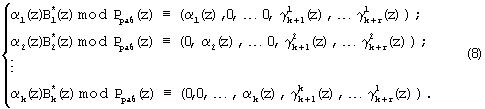
Выражение (8) определяет значения псевдоортогональных полиномов, у которых нарушена ортогональность по контрольным основаниям.Expression (8) determines the values of pseudo-orthogonal polynomials in which orthogonality is violated for control reasons.
Подставив выражение (8) в равенство (6), и учитывая, что в процессе выполнения операции не бывает выход за пределы Pраб(z), получаемSubstituting expression (8) into equality (6), and taking into account that in the process of performing the operation there is no way beyond P slave (z), we obtain

Следовательно, справедливоTherefore fair

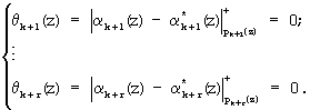
Таким образом, на основании выражения (9) и воспользовавшись значениями псевдоортогональных полиномов, определяемых равенством (8), можно вычислить значения остатков по контрольным основаниям ![]()
![]()

Затем на основании полученных значений ![]()
![]()

Если синдром ошибки равен нулю, т.е.If the error syndrome is zero, i.e.
![]()
![]()
то исходный полином A(z)∈Pраб(z) является разрешенным и не содержит ошибки. В противном случае модулярная комбинация является запрещенной. Тогда в зависимости от величины синдрома ошибки осуществляется коррекция ошибки, т.е.then the original polynomial A (z) ∈P slave (z) is allowed and does not contain errors. Otherwise, the modular combination is prohibited. Then, depending on the magnitude of the error syndrome, error correction is carried out, i.e.
![]()
![]()
![]()
![]()
Структура устройства представлена на фигуре 1. Устройство состоит из регистра 2, предназначенного для хранения остатков по рабочим и контрольным основанием ПСКВ в течение времени обнаружения ошибки, вход которого соединен со входом 1 устройства, блока вычисления синдрома ошибки 3, входы которого соединены с выходами регистра 2, блокам памяти 4, предназначенного для хранения констант - векторов ошибки, входы которого подключены к выходам блока вычисления синдрома ошибки 3, сумматора 5, осуществляющего исправления ошибки путем суммирования исправленной (ошибкой) комбинации кода ПСКВ с вектором ошибки, первый, второй и третий входы которого соединены соответственно с тремя первыми выходами регистра 2 по которым передаются остатки рабочих оснований, а четвертый вход соединен с выходом блока памяти 4, выход сумматора 5 является выходом 6 устройства.The structure of the device is presented in figure 1. The device consists of register 2, intended for storing residuals on the working and control base of the control switch for the detection of errors, the input of which is connected to the input 1 of the device, the unit for calculating the error syndrome 3, the inputs of which are connected to the outputs of register 2 , memory blocks 4, designed to store constants - error vectors, the inputs of which are connected to the outputs of the error syndrome calculation unit 3, adder 5, which corrects errors by summing and corrected (error) combination of the UCS code with the error vector, the first, second and third inputs of which are connected respectively to the first three outputs of register 2 through which the remains of the working bases are transmitted, and the fourth input is connected to the output of memory unit 4, the output of adder 5 is output 6 of the device .
Работа устройство для коррекции ошибок в полиномиальной системе классов вычетов с использованием псевдоортогональных полиномов осуществляется следующим образом. На вход 1 устройства для коррекции ошибок в ПСКВ подается контролируемое число, представленное в полиномиальной формеThe operation of the device for error correction in a polynomial system of residue classes using pseudo-orthogonal polynomials is as follows. At the input 1 of the device for error correction, a controlled number in polynomial form
![]()
![]()
где αi(z) - остаток полинома A(z) по модулю pi(z); p1(z), p2(z), ..., pk(z) - рабочие основания системы ПСКВ; рk+1(z), pk+2(z) - контрольные основания. Данный код записывается в регистр 2. Затем с выхода регистра 2 код ПСКВ в двоичном виде поступает на вход блока вычисления синдрома ошибки 3, который представляет собой двухслойную нейронную сеть. Модулярный код ПСКВ A(z)=(α1(z), α2(z), ..., αk(z), αk+1(z), αk+2(z)) записывается нейронами первого слоя блока вычисления синдрома ошибки 3. С выхода нейронов первого слоя сигналы в двоичном виде поступают на второй слой нейронной сети, который осуществляет вычисление синдрома ошибки согласно выражению (11). С выхода нейронов второго слоя значение синдрома ошибки в двоичном коде θk+1(z), ..., θk+r(z) подается на вход блока 4 памяти, где осуществляется выбор оттуда соответствующей константы ошибки. Эта константа ошибки поступает на четвертый вход сумматора 5, где суммируется со значением A(z)=(α1(z), α2(z), ..., αk(z)), представленным по рабочим основаниям, поступившим с выходов регистра 3 на первые три входа сумматора 5. Исправленное значение A(z) согласно равенству (12) с выхода сумматора 5 подается на выход 6 устройства.where α i (z) is the remainder of the polynomial A (z) modulo p i (z); p 1 (z), p 2 (z), ..., p k (z) are the working bases of the PSKV system; p k + 1 (z), p k + 2 (z) - control grounds. This code is written to register 2. Then, from the output of register 2, the PSCW code in binary form is fed to the input of the error syndrome calculation unit 3, which is a two-layer neural network. The modular PSKV code A (z) = (α 1 (z), α 2 (z), ..., α k (z), α k + 1 (z), α k + 2 (z)) is written by neurons of the first layer of the unit for calculating the error syndrome 3. From the output of the neurons of the first layer, the signals are sent in binary form to the second layer of the neural network, which performs the calculation of the error syndrome according to expression (11). From the output of the neurons of the second layer, the value of the error syndrome in the binary code θ k + 1 (z), ..., θ k + r (z) is fed to the input of the memory unit 4, where the corresponding error constant is selected from there. This error constant is fed to the fourth input of adder 5, where it is summed with the value A (z) = (α 1 (z), α 2 (z), ..., α k (z)), presented on working grounds, received from the outputs of register 3 to the first three inputs of the adder 5. The corrected value A (z) according to equality (12) from the output of the adder 5 is fed to the output 6 of the device.
В качестве примера рассмотрим расширенное поле Галуа GF(24), в котором определены следующие основания:As an example, consider the extended Galois field GF (2 4 ), in which the following bases are defined:
p1(z)=z+1; р2(z)=z2+z+l; p3(z)=z4+z3+z2+z+1; p4(z)=z4+z3+1; p5(z)=z4+z+1, где p1(z), p2(z), р3(z) - рабочие основания, p4(z), p5(z) - контрольные основания ПСКВ. Тогда согласно выражению (1) имеем Pраб(z)=z7+z6+z5+z2+z+1.p 1 (z) = z + 1; p 2 (z) = z 2 + z + l; p 3 (z) = z 4 + z 3 + z 2 + z + 1; p 4 (z) = z 4 + z 3 +1; p 5 (z) = z 4 + z + 1, where p 1 (z), p 2 (z), p 3 (z) are the working bases, p 4 (z), p 5 (z) are the control bases of PSCW . Then, according to expression (1), we have P slave (z) = z 7 + z 6 + z 5 + z 2 + z + 1.
В полной системе оснований ПСКВ поля GF(24) определены следующие ортогональные базисы:The following orthogonal bases are defined in the complete base system of the PSKV field GF (2 4 ):
![]()
![]()
![]()
![]()
![]()
![]()
![]()
![]()
![]()
![]()
Используя сравнимость ортогональных базисов безызбыточной и полной системы по рабочему диапазону, определим значения ортогональных базисов безызбыточной системы оснований p1(z)=z+1; p2(z)=z2+z+1; p3(z)=z4+z3+z2+z+1. ТогдаUsing the comparability of the orthogonal bases of the redundant and complete systems in the operating range, we determine the values of the orthogonal bases of the redundant base system p 1 (z) = z + 1; p 2 (z) = z 2 + z + 1; p 3 (z) = z 4 + z 3 + z 2 + z + 1. Then
![]()
![]()
![]()
![]()
![]()
![]()
На основании полученных значений определим все псевдоортогональные полиномы для ПСКВ GF(24), учитывая невозможность выхода за пределы рабочего диапазона Рраб(z)=z7+z6+z5+z2+z+1. Полученные значения представлены в таблице 1.Based on the obtained values, we define all pseudo-orthogonal polynomials for the PSKV GF (2 4 ), taking into account the impossibility of going beyond the working range P slave (z) = z 7 + z 6 + z 5 + z 2 + z + 1. The obtained values are presented in table 1.
Псевдоортогональные полиномы ПСКВ поля GF(24)Table 1
Pseudo-orthogonal polynomials of PSCW fields GF (2 4 )
Если полином A(z)∈Pраб, то справедливоIf the polynomial A (z) ∈P is slave , then
![]()
![]()
где левая часть равенства представлена по рабочим основаниям p1(z), p2(z), р3(z), средняя часть равенства - получена на основании выражения (10), а правая - модулярная комбинация системы оснований p1(z), р2(z), p3(z), p4(z), p5(z) расширенного поля Галуа GF(24), поступившая на вход устройства для коррекции ошибок в полиномиальной системе классов вычетов с использованием псевдоортогональных полиномов. Тогда согласно (11) имеемwhere the left side of the equality is presented on the working grounds p 1 (z), p 2 (z), p 3 (z), the middle part of the equality is obtained on the basis of expression (10), and the right side is the modular combination of the base system p 1 (z) , p 2 (z), p 3 (z), p 4 (z), p 5 (z) of the extended Galois field GF (2 4 ), received at the input of the device for error correction in a polynomial system of residue classes using pseudo-orthogonal polynomials. Then according to (11) we have
В противном случаеOtherwise

Полученный результат свидетельствует, что поступившая на вход устройства модульная комбинация A(z) содержит ошибку, которую необходимо подвергнуть коррекции. В таблице 2 представлены значения вектора ошибки (0, ..., Δαi(z), ..., 0) - модулярного кода для различных значений синдрома ошибки для ПСКВ поля GF(24).The result obtained indicates that the modular combination A (z) received at the input of the device contains an error that must be corrected. Table 2 presents the values of the error vector (0, ..., Δα i (z), ..., 0) - the modular code for various values of the error syndrome for the PSCW field GF (2 4 ).
Значения вектора ошибки модулярного кода поля GF(24)table 2
Values of the error vector of the modular code of the field GF (2 4 )
Пусть на вход 1 устройства подается полином A(z)=z5+z4+z, значение которого в модулярном коде представляется A(z)=(1, z+1, z3+z2, 0, z2+z4+1).Let the polynomial A (z) = z 5 + z 4 + z be supplied to the input 1 of the device, the value of which in the modular code is represented by A (z) = (1, z + 1, z 3 + z 2 , 0, z 2 + z 4 +1).
Тогда согласно выражению (8) и данных, представленных в таблице 1, получаем следующие псевдоортогональные полиномы Аi(z):Then, according to expression (8) and the data presented in table 1, we obtain the following pseudo-orthogonal polynomials A i (z):
![]()
![]()
![]()
![]()
![]()
![]()
Согласно выражению (10) определяем значения остатков по контрольным основаниям:According to the expression (10) we determine the values of the residues on the control grounds:
![]()
![]()
![]()
![]()
Согласно выражению (11) определяем синдром ошибки:According to the expression (11) we determine the error syndrome:
![]()
![]()
![]()
![]()
Из блока памяти 5 в соответствии с θ4(z)=0, θ5(z)=0 выбирается величина (0, 0, 0), которая складывается с A(z)=(1, z+1, z3+z2), в сумматоре 6 с образованием на выходеFrom memory block 5, in accordance with θ 4 (z) = 0, θ 5 (z) = 0, the quantity (0, 0, 0) is selected, which is added to A (z) = (1, z + 1, z 3 + z 2 ), in the adder 6 with the formation of the output
![]()
![]()
Допустим, что в принятой комбинации произошла ошибка по третьему основанию и ее глубина равна Δα3(z)=z2+z. Тогда имеемSuppose that an error occurred on the third base in the adopted combination and its depth is Δα 3 (z) = z 2 + z. Then we have
![]()
![]()
Тогда согласно выражению (8) и данных, представленных в таблице 1, получаем следующие псевдоортогональные полиномы Ai(z):Then, according to expression (8) and the data presented in table 1, we obtain the following pseudo-orthogonal polynomials A i (z):
![]()
![]()
![]()
![]()
![]()
![]()
Согласно выражению (10) определяем значения остатков по контрольным основаниям:According to the expression (10) we determine the values of the residues on the control grounds:
![]()
![]()
![]()
![]()
Согласно выражению (11) определяем синдром ошибки:According to the expression (11) we determine the error syndrome:
![]()
![]()
![]()
![]()
Из блока памяти 5 в соответствии с θ4(z)=1, θ5(z)=z3+z2+z+1 выбирается величина (0, 0, z2+z), которая складывается с A(z)=(1, z+1, z3+z) в сумматоре 6 с образованием на выходеFrom memory block 5, in accordance with θ 4 (z) = 1, θ 5 (z) = z 3 + z 2 + z + 1, the quantity (0, 0, z 2 + z) is selected, which is added to A (z) = (1, z + 1, z 3 + z) in adder 6 with output formation
![]()
![]()
Ошибка в модулярном коде исправлена.A bug in the modular code has been fixed.
Блок вычисления синдрома ошибки представлен на фиг.2. Блок вычисления синдрома ошибки имеет 5 входов, по первым трем из которых подаются остатки α1(z), α2(2), α3(z) по рабочим основанием p1(z), p2(z), р3(z), по четвертому и пятому поступают остатки α4(z) и α5(z) по контрольным основаниям p4(z) и p5(z). Блок вычисления синдрома представляет собой двухслойную нейронную сеть. Первый слой содержит 15 нейронов. Входы нейронов 7, 8-9, 10-13 подключены соответственно к первому, второму и третьему входу блока вычисления синдрома ошибки. Входы нейронов 14-17 и 18-21 подключены соответственно к четвертому и пятому входам блока вычисления синдрома ошибок. На входы нейронов 7, 8-9, 10-13 в двоичном виде поступают остатки α1(z), α2(z), α3(z) по трем рабочим основаниям ПСКВ. На нейроны 14-17 поступает двоичный код α4(z) по первому контрольному модулю p4(z)=z4+z3+1. На нейроны 18-21 в двоичном коде поступает в двоичном коде α5(z) по второму контрольному модулю p5(z)=z4+z+1. Старшие разряды остатков полинома α1(z), α2(z), α3(z), α4(z), α5(z) записываются соответственно в нейроны 7, 8, 10, 14, 18 первого слоя. Второй слой нейронной сети содержит 8 нейронов, выполняющих базовую операцию согласно выражению (11), причем первые четыре нейрона 22-25 определяют значение θ4(z), остальные нейроны 26-29 определяют значение θ5(z). Входы нейрона 22 второго слоя соединены с выходами нейронов 7, 8, 13, 14 первого слоя. Входы нейрона 23 второго слоя соединены с выходами нейронов 9, 10, 13, 15 первого слоя. Входы нейрона 24 второго слоя соединены с выходами 7, 8, 9, 11, 12, 16 нейронов первого слоя. Входы нейрона 25 второго слоя соединены с выходами 7, 9, 12, 13, 17 нейронов первого слоя. Входы нейрона 26 второго слоя соединены с выходами 9, 11, 13, 18 нейронов первого слоя. Входы нейрона 27 второго слоя соединены с выходами 8, 12, 19 нейронов первого слоя. Входы нейрона 28 второго слоя соединены с выходами 7, 8, 10, 12, 13, 20 нейронов первого слоя. Входы нейрона 29 второго слоя соединен с выходами нейронов 8, 9, 10, 12, 21 нейронов первого слоя. Старшие значения синдрома ошибки θ4(z) и θ5(z) соответственно вычисляются в нейронах 22 и 26. Выходы нейронов второго слоя являются выход блока вычисления синдрома ошибки.The error syndrome calculation unit is shown in FIG. The error syndrome calculation unit has 5 inputs, the first three of which are the residues α 1 (z), α 2 (2), α 3 (z) based on the working base p 1 (z), p 2 (z), p 3 ( z), in the fourth and fifth, residues α 4 (z) and α 5 (z) are received for the control bases p 4 (z) and p 5 (z). The syndrome calculation unit is a two-layer neural network. The first layer contains 15 neurons. The inputs of
Рассмотрим процесс работы блока вычисления синдрома ошибки на примерах. Пусть на вход устройства коррекции ошибки был подан модулярный код A(z)=(1, z+1, z3+z2, 0, z2+z+1). Данный код поступает на входы нейронов первого слоя блока вычисления синдрома ошибки. Сигналы на выходе нейронов первого слоя представлены в таблице 3.Consider the process of the unit for computing the error syndrome using examples. Let the modular code A (z) = (1, z + 1, z 3 + z 2 , 0, z 2 + z + 1) be fed to the input of the error correction device. This code is fed to the inputs of the neurons of the first layer of the error syndrome calculation unit. The signals at the output of neurons of the first layer are presented in table 3.
Сигналы на выходе нейронов первого слояTable 3
Signals at the output of neurons of the
Сигналы с выходов нейронов первого слоя поступают на соответствующие входы нейронов второго слоя. В таблице 4 представлены значения сигналов на входе и на выходе нейронов второго слоя. Символ «-» соответствует отсутствию связи между нейронами второго и первого слоя.The signals from the outputs of the neurons of the first layer are fed to the corresponding inputs of the neurons of the second layer. Table 4 shows the values of the signals at the input and output of the neurons of the second layer. The symbol “-” corresponds to the absence of communication between the neurons of the second and first layer.
Сигналы на выходе нейронов второго слояTable 4
Signals at the output of neurons of the
Допустим, что в принятой комбинации произошла ошибка по третьему основанию и ее глубина равна Δα3(z)=z2+z. Тогда имеемSuppose that an error occurred on the third base in the adopted combination and its depth is Δα 3 (z) = z 2 + z. Then we have
![]()
![]()
Данный код поступает на входы нейронов первого слоя блока вычисления синдрома ошибки. Сигналы на выходе нейронов первого слоя представлены в таблице 5.This code is fed to the inputs of the neurons of the first layer of the error syndrome calculation unit. The signals at the output of neurons of the first layer are presented in table 5.
Сигналы на выходе нейронов первого слояTable 5
Signals at the output of neurons of the
Сигналы с выходов нейронов первого слоя поступают на соответствующие входы нейронов второго слоя. В таблице 6 представлены значения сигналов на входе и на выходе нейронов второго слоя.The signals from the outputs of the neurons of the first layer are fed to the corresponding inputs of the neurons of the second layer. Table 6 presents the values of the signals at the input and output of the neurons of the second layer.
Сигналы на выходе нейронов второго слояTable 6
Signals at the output of neurons of the
Таким образом, на выходе блока вычисления синдрома ошибки определены значения θ4(z)=1, θ5(z)=z3+z2+z+1. Полученные данные совпадают с контрольными просчетами, представленными ранее.Thus, at the output of the error syndrome calculation unit, the values θ 4 (z) = 1, θ 5 (z) = z 3 + z 2 + z + 1 are determined. The data obtained coincide with the control miscalculations presented earlier.
Claims (1)
Priority Applications (1)
| Application Number | Priority Date | Filing Date | Title |
|---|---|---|---|
| RU2005113806/09A RU2294529C2 (en) | 2005-05-05 | 2005-05-05 | Device for correcting errors in polynomial system of residue classes with usage of pseudo-orthogonal polynomials |
Applications Claiming Priority (1)
| Application Number | Priority Date | Filing Date | Title |
|---|---|---|---|
| RU2005113806/09A RU2294529C2 (en) | 2005-05-05 | 2005-05-05 | Device for correcting errors in polynomial system of residue classes with usage of pseudo-orthogonal polynomials |
Publications (2)
| Publication Number | Publication Date |
|---|---|
| RU2005113806A RU2005113806A (en) | 2006-11-10 |
| RU2294529C2 true RU2294529C2 (en) | 2007-02-27 |
Family
ID=37500651
Family Applications (1)
| Application Number | Title | Priority Date | Filing Date |
|---|---|---|---|
| RU2005113806/09A RU2294529C2 (en) | 2005-05-05 | 2005-05-05 | Device for correcting errors in polynomial system of residue classes with usage of pseudo-orthogonal polynomials |
Country Status (1)
| Country | Link |
|---|---|
| RU (1) | RU2294529C2 (en) |
Cited By (4)
| Publication number | Priority date | Publication date | Assignee | Title |
|---|---|---|---|---|
| RU2560823C1 (en) * | 2014-03-12 | 2015-08-20 | Федеральное государственное автономное образовательное учреждение высшего профессионального образования "Северо-Кавказский федеральный университет" | Device for correcting errors in polynomial system of classes |
| RU2562366C1 (en) * | 2014-03-12 | 2015-09-10 | Федеральное государственное автономное образовательное учреждение высшего профессионального образования "Северо-Кавказский федеральный университет" | Apparatus for expanding modular code bases |
| RU2622881C1 (en) * | 2016-07-05 | 2017-06-20 | федеральное государственное автономное образовательное учреждение высшего образования "Северо-Кавказский федеральный университет" | Device for calculating the amount of steam works in the polynomial system of the classes of deductions |
| RU2711731C1 (en) * | 2019-07-19 | 2020-01-21 | федеральное государственное автономное образовательное учреждение высшего образования "Северо-Кавказский федеральный университет" | Apparatus for calculating sums of pair products |
-
2005
- 2005-05-05 RU RU2005113806/09A patent/RU2294529C2/en not_active IP Right Cessation
Non-Patent Citations (1)
| Title |
|---|
| ЧЕРВЯКОВ Н.И. и др. Математическая модель нейронных сетей для исследований ортогональных преобразований сигналов в расширенных полях Галуа. Нейрокомпьютеры: разработка, применение. №6, 2003, с.66-67. * |
Cited By (4)
| Publication number | Priority date | Publication date | Assignee | Title |
|---|---|---|---|---|
| RU2560823C1 (en) * | 2014-03-12 | 2015-08-20 | Федеральное государственное автономное образовательное учреждение высшего профессионального образования "Северо-Кавказский федеральный университет" | Device for correcting errors in polynomial system of classes |
| RU2562366C1 (en) * | 2014-03-12 | 2015-09-10 | Федеральное государственное автономное образовательное учреждение высшего профессионального образования "Северо-Кавказский федеральный университет" | Apparatus for expanding modular code bases |
| RU2622881C1 (en) * | 2016-07-05 | 2017-06-20 | федеральное государственное автономное образовательное учреждение высшего образования "Северо-Кавказский федеральный университет" | Device for calculating the amount of steam works in the polynomial system of the classes of deductions |
| RU2711731C1 (en) * | 2019-07-19 | 2020-01-21 | федеральное государственное автономное образовательное учреждение высшего образования "Северо-Кавказский федеральный университет" | Apparatus for calculating sums of pair products |
Also Published As
| Publication number | Publication date |
|---|---|
| RU2005113806A (en) | 2006-11-10 |
Similar Documents
| Publication | Publication Date | Title |
|---|---|---|
| WO2014113226A1 (en) | Syndrome of degraded quantum redundancy coded states | |
| JPS6041770B2 (en) | Error checking and correction system | |
| JP3232602B2 (en) | Euclidean circuit | |
| RU2294529C2 (en) | Device for correcting errors in polynomial system of residue classes with usage of pseudo-orthogonal polynomials | |
| GB2216690A (en) | Error detecting/correction | |
| EP0787325A4 (en) | Error correction method and apparatus for disk drive emulator | |
| JPS645334B2 (en) | ||
| RU2300801C2 (en) | Device for finding and correcting errors in codes of polynomial system of residue classes based on zeroing | |
| Garden | Markov analysis of viral DNA/RNA sequences | |
| RU2622881C1 (en) | Device for calculating the amount of steam works in the polynomial system of the classes of deductions | |
| US11473940B2 (en) | Absolute linear encoder | |
| RU2267808C2 (en) | Device for detecting and correcting errors in polynomial residual-class system | |
| RU2309535C1 (en) | Device for transforming a number from polynomial system of residual classes to positional code with error correction | |
| RU2270475C2 (en) | Device for calculating sums of paired results of multiplications in polynomial system of residual classes | |
| RU2390051C2 (en) | Device for spectral error detection and correction in codes of polynomial system of residue classes | |
| RU2301442C2 (en) | Neuron network for finding, localizing and correcting errors in residual classes system | |
| US7188294B2 (en) | High-efficiency error detection and/or correction code | |
| RU2393529C2 (en) | Device for correction of errors in polynomial system of deduction classes with application of pseudo-orthogonal polynomials | |
| RU2653257C1 (en) | Device for detecting and correcting the error of the modular code | |
| US20080104487A1 (en) | Error detection apparatus and error detection method | |
| RU2301441C2 (en) | Device for spectral detection and correction of errors in codes of polynomial residue classes system | |
| RU2652446C1 (en) | Device for errors correction in modular code based on basic system expansion | |
| JP2000295116A (en) | Error correction encoding method | |
| RU2818029C1 (en) | Device for correcting errors in polynomial system of residue classes | |
| RU2453902C2 (en) | Device for correcting errors in polynomial system of residue classes |
Legal Events
| Date | Code | Title | Description |
|---|---|---|---|
| MM4A | The patent is invalid due to non-payment of fees |
Effective date: 20070506 |