RU2293247C2 - Heat-insulating pipe for pipelines and method of its manufacturing - Google Patents
Heat-insulating pipe for pipelines and method of its manufacturing Download PDFInfo
- Publication number
- RU2293247C2 RU2293247C2 RU2002123325/06A RU2002123325A RU2293247C2 RU 2293247 C2 RU2293247 C2 RU 2293247C2 RU 2002123325/06 A RU2002123325/06 A RU 2002123325/06A RU 2002123325 A RU2002123325 A RU 2002123325A RU 2293247 C2 RU2293247 C2 RU 2293247C2
- Authority
- RU
- Russia
- Prior art keywords
- plastic
- plastic film
- pipe
- heat
- outer coating
- Prior art date
Links
Images
Classifications
-
- B—PERFORMING OPERATIONS; TRANSPORTING
- B29—WORKING OF PLASTICS; WORKING OF SUBSTANCES IN A PLASTIC STATE IN GENERAL
- B29C—SHAPING OR JOINING OF PLASTICS; SHAPING OF MATERIAL IN A PLASTIC STATE, NOT OTHERWISE PROVIDED FOR; AFTER-TREATMENT OF THE SHAPED PRODUCTS, e.g. REPAIRING
- B29C44/00—Shaping by internal pressure generated in the material, e.g. swelling or foaming ; Producing porous or cellular expanded plastics articles
- B29C44/02—Shaping by internal pressure generated in the material, e.g. swelling or foaming ; Producing porous or cellular expanded plastics articles for articles of definite length, i.e. discrete articles
- B29C44/12—Incorporating or moulding on preformed parts, e.g. inserts or reinforcements
- B29C44/14—Incorporating or moulding on preformed parts, e.g. inserts or reinforcements the preformed part being a lining
- B29C44/16—Incorporating or moulding on preformed parts, e.g. inserts or reinforcements the preformed part being a lining shaped by the expansion of the material
-
- B—PERFORMING OPERATIONS; TRANSPORTING
- B29—WORKING OF PLASTICS; WORKING OF SUBSTANCES IN A PLASTIC STATE IN GENERAL
- B29C—SHAPING OR JOINING OF PLASTICS; SHAPING OF MATERIAL IN A PLASTIC STATE, NOT OTHERWISE PROVIDED FOR; AFTER-TREATMENT OF THE SHAPED PRODUCTS, e.g. REPAIRING
- B29C44/00—Shaping by internal pressure generated in the material, e.g. swelling or foaming ; Producing porous or cellular expanded plastics articles
- B29C44/20—Shaping by internal pressure generated in the material, e.g. swelling or foaming ; Producing porous or cellular expanded plastics articles for articles of indefinite length
- B29C44/32—Incorporating or moulding on preformed parts, e.g. linings, inserts or reinforcements
- B29C44/322—Incorporating or moulding on preformed parts, e.g. linings, inserts or reinforcements the preformed parts being elongated inserts, e.g. cables
-
- F—MECHANICAL ENGINEERING; LIGHTING; HEATING; WEAPONS; BLASTING
- F16—ENGINEERING ELEMENTS AND UNITS; GENERAL MEASURES FOR PRODUCING AND MAINTAINING EFFECTIVE FUNCTIONING OF MACHINES OR INSTALLATIONS; THERMAL INSULATION IN GENERAL
- F16L—PIPES; JOINTS OR FITTINGS FOR PIPES; SUPPORTS FOR PIPES, CABLES OR PROTECTIVE TUBING; MEANS FOR THERMAL INSULATION IN GENERAL
- F16L59/00—Thermal insulation in general
- F16L59/14—Arrangements for the insulation of pipes or pipe systems
- F16L59/143—Pre-insulated pipes
-
- F—MECHANICAL ENGINEERING; LIGHTING; HEATING; WEAPONS; BLASTING
- F16—ENGINEERING ELEMENTS AND UNITS; GENERAL MEASURES FOR PRODUCING AND MAINTAINING EFFECTIVE FUNCTIONING OF MACHINES OR INSTALLATIONS; THERMAL INSULATION IN GENERAL
- F16L—PIPES; JOINTS OR FITTINGS FOR PIPES; SUPPORTS FOR PIPES, CABLES OR PROTECTIVE TUBING; MEANS FOR THERMAL INSULATION IN GENERAL
- F16L59/00—Thermal insulation in general
- F16L59/14—Arrangements for the insulation of pipes or pipe systems
- F16L59/153—Arrangements for the insulation of pipes or pipe systems for flexible pipes
-
- B—PERFORMING OPERATIONS; TRANSPORTING
- B29—WORKING OF PLASTICS; WORKING OF SUBSTANCES IN A PLASTIC STATE IN GENERAL
- B29C—SHAPING OR JOINING OF PLASTICS; SHAPING OF MATERIAL IN A PLASTIC STATE, NOT OTHERWISE PROVIDED FOR; AFTER-TREATMENT OF THE SHAPED PRODUCTS, e.g. REPAIRING
- B29C44/00—Shaping by internal pressure generated in the material, e.g. swelling or foaming ; Producing porous or cellular expanded plastics articles
- B29C44/02—Shaping by internal pressure generated in the material, e.g. swelling or foaming ; Producing porous or cellular expanded plastics articles for articles of definite length, i.e. discrete articles
- B29C44/12—Incorporating or moulding on preformed parts, e.g. inserts or reinforcements
- B29C44/1214—Anchoring by foaming into a preformed part, e.g. by penetrating through holes
-
- B—PERFORMING OPERATIONS; TRANSPORTING
- B29—WORKING OF PLASTICS; WORKING OF SUBSTANCES IN A PLASTIC STATE IN GENERAL
- B29C—SHAPING OR JOINING OF PLASTICS; SHAPING OF MATERIAL IN A PLASTIC STATE, NOT OTHERWISE PROVIDED FOR; AFTER-TREATMENT OF THE SHAPED PRODUCTS, e.g. REPAIRING
- B29C44/00—Shaping by internal pressure generated in the material, e.g. swelling or foaming ; Producing porous or cellular expanded plastics articles
- B29C44/20—Shaping by internal pressure generated in the material, e.g. swelling or foaming ; Producing porous or cellular expanded plastics articles for articles of indefinite length
- B29C44/32—Incorporating or moulding on preformed parts, e.g. linings, inserts or reinforcements
- B29C44/326—Joining the preformed parts, e.g. to make flat or profiled sandwich laminates
Abstract
Description
Изобретение относится к теплоизолированной трубе для трубопроводов, согласно ограничительной части п.1 формулы изобретения, а также к способу изготовления теплоизолированной трубы для трубопроводов, согласно ограничительной части п.5 и п.7 формулы изобретения.The invention relates to a heat-insulated pipe for pipelines, according to the restrictive part of claim 1 of the claims, as well as to a method for manufacturing a heat-insulated pipe for pipelines, according to the restrictive part of claim 5 and claim 7 of the claims.
Из CH-PS 451621 известна гибкая теплоизолированная труба для трубопроводов которая состоит из гофрированной металлической внутренней трубы, концентрично и на расстоянии от нее расположена гофрированная металлическая наружная труба, а между ними находится теплоизоляционный слой из полиуретана. Наружная труба имеет поверхность из пластмассы.A flexible thermally insulated pipe for pipelines is known from CH-PS 451621 which consists of a corrugated metal inner pipe, a corrugated metal outer pipe is concentrically and at a distance from it, and between them there is a heat-insulating layer of polyurethane. The outer pipe has a plastic surface.
Эта известная труба для трубопроводов пригодна для транспортировки тепла, подаваемого по сетям централизованного теплоснабжения. Труба для трубопроводов может транспортироваться на длину до 1000 м на кабельном барабане как электрический кабель в виде одного куска без соединительных элементов.This well-known pipe for pipelines is suitable for conveying heat supplied through district heating networks. Pipe for pipelines can be transported to a length of 1000 m on a cable drum as an electric cable in the form of a single piece without connecting elements.
Из немецкой заявки на полезную модель №9407409 известна труба для трубопроводов, которая выполнена на основе конструкции трубы известной из CH-PS 451621. На месте гофрированной металлической наружной трубы здесь используется оболочка из просечно-вытяжной стали, на которой расположена диффузионно-непроницаемая пленка. Диффузионно-непроницаемая пленка может быть металлической пленкой или пластмассовой пленкой. Пленка служит ограничителем формы для заполненного вспененным материалом кольцеобразного пространства между внутренней и наружной трубой. Кроме того, пленка служит стопором для пара или диффузии.A pipe for pipelines is known from the German application for utility model No. 9407409, which is based on the construction of a pipe known from CH-PS 451621. In place of the corrugated metal outer pipe, an expanded steel sheath is used here, on which a diffusion-impermeable film is located. The diffusion impermeable film may be a metal film or a plastic film. The film serves as a shape limiter for the annular space filled with foam material between the inner and outer tubes. In addition, the film serves as a stopper for vapor or diffusion.
Преимущество такой трубы для трубопроводов по сравнению с трубой из описания изобретения к патенту Швейцарии №451621 состоит в том, что при практически одинаковых механических свойствах обеспечивается существенное снижение веса.The advantage of such a pipe for pipelines compared with the pipe from the description of the invention to Swiss patent No. 451621 is that with almost the same mechanical properties, a significant reduction in weight is achieved.
Обе трубных конструкции имеют недостаток, заключающийся в том, что пластмассовое покрытие имеет гладкую поверхность, ограничивающую гибкость трубы для трубопроводов.Both pipe structures have the disadvantage that the plastic coating has a smooth surface that limits the flexibility of the pipe for piping.
Поэтому в основу заявленного изобретения положена задача усовершенствования образующей серию трубы для трубопроводов таким образом, чтобы она обладала повышенной гибкостью.Therefore, the basis of the claimed invention is the task of improving forming a series of pipes for pipelines so that it has increased flexibility.
Указанная задача решается с помощью признаков, приведенных в отличительной части п.1 формулы изобретения.This problem is solved using the signs given in the characterizing part of claim 1 of the claims.
Существенное преимущество изобретения состоит в том, что пена, образующаяся в кольцевом зазоре между внутренней трубой и оболочкой из просечно-вытяжной стали или охватывающей оболочку из просечно-вытяжной стали пленкой, проникает через отверстия оболочки из просечно-вытяжной стали и на участках пленки между витками винтообразно нанесенного жгута образует направленную наружу выпуклость. Таким образом, оболочка из просечно-вытяжной стали оказывается полностью утопленной в пенопласте. Выпуклостями создается винтообразный гофр. Нанесенное затем методом экструзии наружное покрытие заполняет впадины между гофрами, в результате чего образуется винтообразный гофрированный контур наружного пластмассового покрытия.A significant advantage of the invention is that the foam formed in the annular gap between the inner tube and the expanded steel shell or the film covering the expanded steel shell penetrates through the holes of the expanded steel shell and in the portions of the film between the turns is screw-shaped The applied tourniquet forms an outward bulge. Thus, the shell of expanded metal is completely recessed in the foam. The bulges create a helical corrugation. The outer coating, then applied by extrusion, fills the hollows between the corrugations, resulting in the formation of a helical corrugated contour of the outer plastic coating.
Более подробно изобретение поясняется с помощью примеров его осуществления, схематически изображенных на фиг.1 и 2.The invention is explained in more detail using examples of its implementation, schematically depicted in figures 1 and 2.
На фиг.1 представлен боковой разрез трубы для трубопроводов согласно изобретению.Figure 1 shows a side section of a pipe for pipelines according to the invention.
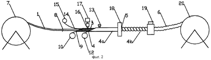
На фиг.2 - способ изготовления теплоизолированной трубы для трубопроводов.Figure 2 - a method of manufacturing a thermally insulated pipe for pipelines.
Труба для трубопроводов состоит из внутренней трубы 1, преимущественно продольно сваренной, гофрированной металлической трубы, предпочтительно из нержавеющей стали, теплоизоляционного слоя 2 пенопласта на основе полиуретана или полиизоцианурата, концентрично по отношению к внутренней трубе 1 сформирована оболочка 3 из просечно-вытяжной стальной ленты, пластмассовой пленки 4, преимущественно двухслойной пленки из полиэтилентерефталата и полиэтилена низкой плотности, узкого, винтообразного пластмассового жгута 5, нанесенного с расстоянием между отдельными витками и состоящего преимущественно из трехслойной пленки из полиэтилен-полиэтилентерефталат-полиэтилена, и наружного пластмассового покрытия 6, предпочтительно из полиэтилена. Пластмассовая пленка 4 может быть металлизированной или содержать покрытие из оксида кремния. В результате повышается диффузионная плотность трубной конструкции.The pipe for pipelines consists of an inner pipe 1, mainly longitudinally welded, corrugated metal pipe, preferably stainless steel, a heat-insulating layer 2 of polyurethane foam or polyisocyanurate, concentric with respect to the inner pipe 1, a sheath 3 is formed of expanded metal steel tape, plastic film 4, mainly a two-layer film of polyethylene terephthalate and low density polyethylene, a narrow, screw-like plastic bundle 5, applied at a distance iem between the individual windings and consisting essentially of a three-layer film of polyethylene terephthalate, polyethylene, and the outer plastic cover 6, preferably of polyethylene. The plastic film 4 may be metallized or contain a coating of silicon oxide. As a result, the diffusion density of the pipe structure increases.
Пластмассовая пленка 4 имеет винтообразное волнистое расположение, при этом впадины между гофрами образованы в результате удерживания участков пластмассовой пленки 4 в нижнем положении пластмассового жгута 5. Участки 6а между двумя впадинами гофров заполнены пенопластом. Пластмассовое наружное покрытие 6 повторяет контур пластмассовой пленки 4 и, следовательно, имеет винтообразную волнистость, в результате которой повышается гибкость трубы для трубопроводов по сравнению с трубой такой же конструкции, но с гладким пластмассовым наружным покрытием.The plastic film 4 has a helical wavy arrangement, while the hollows between the corrugations are formed by holding sections of the plastic film 4 in the lower position of the plastic bundle 5. The sections 6a between the two hollows of the corrugations are filled with foam. The plastic outer coating 6 follows the contour of the plastic film 4 and, therefore, has a helical undulation, which increases the flexibility of the pipe for pipelines compared to a pipe of the same design, but with a smooth plastic outer coating.
На фиг.2 представлен технологический процесс изготовления теплоизолированной трубы для трубопроводов.Figure 2 presents the technological process of manufacturing a thermally insulated pipe for pipelines.
С накопительного барабана 7 разматывают внутреннюю трубу 1, которую вводят в направляющую трубу 8. Ленту 9 из просечно-вытяжной стали разматывают с накопительной бобины 10 и формируют в оболочку 3, располагаемую вокруг внутренней трубы 1 с промежутком. Вокруг оболочки 3 из просечно-вытяжной стали свободно формируют пластмассовую пленку 4, сматываемую с накопительной бобины 12, и сваривают ее по продольным кромкам с помощью сварочного устройства 13. Внутреннюю или внутренние трубы направляют посредством направляющей трубы 8 концентрично к пластмассовой пленке 4 или оболочке 3 из просечно-вытяжной стали.From the storage drum 7, the inner pipe 1 is unwound, which is introduced into the guide pipe 8. The tape 9 from expanded metal is unwound from the
В кольцевой зазор между внутренней трубой 1 и оболочкой 3 из просечно-вытяжной стали укладывается одна или несколько жил 14 датчика или сигнального устройства, которые должны сообщать или определять нахождение проникшей в трубу влаги. Позицией 15 обозначена накопительная бобина для жил 14 датчика или сигнального устройства.In the annular gap between the inner pipe 1 and the shell 3 of expanded steel, one or more cores 14 of the sensor or signal device are laid, which must communicate or determine the presence of moisture penetrated into the pipe.
Через смесительное устройство 16 из сборной емкости 17 нагнетается вспениваемая композиция из полиола и изоцианата в кольцевой зазор между внутренней трубой 1 и оболочкой 3 из просечно-вытяжной стали. Пенная композиция задается таким образом, что она начинает вспениваться за сварочным устройством 13. Образующаяся пена проникает при этом через отверстия в просечно-вытяжной стали и заполняет незначительный зазор между оболочкой 3 из просечно-вытяжной стали и трубой 4а из пластмассовой пленки 4.A foaming composition of polyol and isocyanate is pumped through a
С помощью ленточного намоточного устройства 18 пластмассовый жгут 5 наносят в виде витков на участки трубы 4а, в результате чего участки трубы 4а, вокруг которых обматывают пластмассовый жгут 5, укладывают на оболочку 3 из просечно-вытяжной стали.Using a
Теперь пенопласт полностью заполняет трубу 4а перед намоткой пластмассового жгута 5. В этом случае сохраняющийся еще мягким пенопласт вытесняется пластмассовым жгутом 5, в результате чего образуется винтообразная волнистость трубы 4а (см. 4b).Now the foam completely fills the pipe 4a before winding the plastic bundle 5. In this case, the foam still remaining soft is forced out by the plastic bundle 5, as a result of which a spiral-like corrugation of the pipe 4a is formed (see 4b).
В качестве альтернативы вспененный материал выполнен с возможностью вспенивания лишь после намотки пластмассового жгута 5, образуя между отдельными витками пластмассового жгута 5 участки с направленной наружу выпуклостью, в результате чего получают гофрированную трубу 4b.Alternatively, the foamed material is capable of foaming only after winding the plastic bundle 5, forming sections with outward convexity between the individual turns of the plastic bundle 5, resulting in a
Затем гофрированная труба 4b поступает в экструдер 19, в котором наносят наружное покрытие 6, в частности таким образом, что оно повторяет волнистость трубы 4b.Then the
После этого трубу для трубопроводов наматывают на кабельный барабан 20.After that, the pipe for pipelines is wound on a
С помощью описанного способа можно получать в непрерывном режиме теплоизолированные трубы большой длины для трубопроводов, доставляемые к месту прокладки на кабельных барабанах и укладываемые кусками длиной до 1000 м каждый, т.е. без применения соединительных муфт.Using the described method, it is possible to continuously produce large-length insulated pipes for pipelines delivered to the place of installation on cable drums and stacked in pieces of up to 1000 m each, i.e. without the use of couplings.
Claims (8)
Applications Claiming Priority (2)
| Application Number | Priority Date | Filing Date | Title |
|---|---|---|---|
| DE10142719.0 | 2001-08-31 | ||
| DE10142719A DE10142719A1 (en) | 2001-08-31 | 2001-08-31 | Heat insulated pipe |
Publications (2)
| Publication Number | Publication Date |
|---|---|
| RU2002123325A RU2002123325A (en) | 2004-06-27 |
| RU2293247C2 true RU2293247C2 (en) | 2007-02-10 |
Family
ID=7697274
Family Applications (1)
| Application Number | Title | Priority Date | Filing Date |
|---|---|---|---|
| RU2002123325/06A RU2293247C2 (en) | 2001-08-31 | 2002-08-30 | Heat-insulating pipe for pipelines and method of its manufacturing |
Country Status (7)
| Country | Link |
|---|---|
| EP (1) | EP1288558B1 (en) |
| AT (1) | ATE257233T1 (en) |
| DE (2) | DE10142719A1 (en) |
| DK (1) | DK1288558T3 (en) |
| PL (1) | PL199736B1 (en) |
| RU (1) | RU2293247C2 (en) |
| TR (1) | TR200400104T4 (en) |
Cited By (3)
| Publication number | Priority date | Publication date | Assignee | Title |
|---|---|---|---|---|
| WO2012002834A1 (en) | 2010-06-28 | 2012-01-05 | Общество С Ограниченной Ответственностью "Cmиt-Яpцebo" | Method for manufacturing a thermally insulated flexible tube |
| WO2012039638A1 (en) | 2010-09-20 | 2012-03-29 | Общество С Ограниченной Ответственностью "Cmиt-Яpцebo" | Line for manufacturing a heat-insulated flexible pipe |
| RU2629102C2 (en) * | 2011-11-28 | 2017-08-24 | Басф Се | Continuous method of manufacturing isolated pipes, isolated pipe, device for manufacturing this isolated pipe and application of said device |
Families Citing this family (23)
| Publication number | Priority date | Publication date | Assignee | Title |
|---|---|---|---|---|
| CA2518456C (en) | 2003-03-05 | 2013-01-08 | Bhp Billiton Petroleum Pty Ltd | Hose end fitting |
| DE20303698U1 (en) * | 2003-03-08 | 2003-05-15 | Brugg Rohrsysteme Gmbh | Heat insulated pipe |
| DE102004046656A1 (en) * | 2004-09-25 | 2006-04-06 | Preh Gmbh | Thermally insulated flexible conduit and method and apparatus for making a conduit |
| CA2651578C (en) | 2006-05-08 | 2014-12-02 | Bhp Billiton Petroleum Pty Ltd | Improvements relating to hose |
| ES2640772T3 (en) | 2006-05-08 | 2017-11-06 | Bhp Billiton Innovation Pty Ltd | Improvements related to flexible pipes |
| GB0609079D0 (en) | 2006-05-08 | 2006-06-21 | Bhp Billiton Petroleum Pty Ltd | Improvements relating to hose |
| GB0612991D0 (en) | 2006-06-29 | 2006-08-09 | Bhp Billiton Petroleum Pty Ltd | Improvements relating to hose |
| GB0616052D0 (en) | 2006-08-11 | 2006-09-20 | Bhp Billiton Petroleum Pty Ltd | Improvements relating to hose |
| GB0616053D0 (en) | 2006-08-11 | 2006-09-20 | Bhp Billiton Petroleum Pty Ltd | Improvements relating to hose |
| MY154456A (en) | 2007-09-14 | 2015-06-15 | Bhp Billiton Petroleum Pty Ltd | Hose |
| DE102007054269A1 (en) | 2007-11-14 | 2009-05-28 | Jarus Gmbh | Thermally insulated conduit and process for its manufacture |
| CH699570A1 (en) * | 2008-09-26 | 2010-03-31 | Brugg Rohr Ag Holding | Heat insulated conductive pipe manufacturing method for industrial water- and long distance heat supply, involves cutting and/or spraying outer pipe at points, and introducing insulated inner pipe into outer pipe, and closing outer pipe |
| US9441766B2 (en) | 2009-06-02 | 2016-09-13 | Bhp Billiton Petroleum Pty Ltd. | Reinforced hose |
| DE102012217641A1 (en) * | 2012-09-27 | 2014-03-27 | Witzenmann Gmbh | Flexible duct element for use in e.g. solar-thermal power plant, has outer wall enclosing inner wall at distance such that gap is formed, where gap has width that lies between two and twenty-times of thickness of inner wall or outer wall |
| CA2942810C (en) | 2014-03-28 | 2021-02-16 | Public Joint Stock Company "Transneft" | Method for thermally insulating welded joints of pre-insulated pipes |
| DE102015109313B4 (en) * | 2015-06-11 | 2018-02-01 | Brugg Rohr Ag, Holding | Double-walled conduit with a thermal barrier coating and a dedicated plastic outer tube |
| DE102015221898B4 (en) * | 2015-11-06 | 2017-11-16 | Continental Automotive Gmbh | Method for producing a structural unit and structural unit |
| US10293528B2 (en) | 2016-08-02 | 2019-05-21 | Thermacor Process, Inc. | Continuous method for producing pre-insulated piping |
| US10293527B2 (en) | 2016-08-02 | 2019-05-21 | Thermacor Process, Inc. | Continuous method for producing pre-insulated piping |
| CN107696519A (en) * | 2017-09-29 | 2018-02-16 | 镇江春环密封件集团有限公司 | A kind of production method of polyfluortetraethylecomposite composite pipe |
| DE102018117979A1 (en) * | 2018-07-25 | 2020-01-30 | Brugg Rohr Ag Holding | Double-walled conduit and an optical fiber for such a conduit |
| IT201900020781A1 (en) | 2019-11-11 | 2021-05-11 | Ecotech S R L | Thermo-insulated tube |
| CN113915456A (en) * | 2021-09-23 | 2022-01-11 | 太仓京和机电有限公司 | Thermal insulation pipe sleeving method and air conditioner pipe assembly |
Family Cites Families (7)
| Publication number | Priority date | Publication date | Assignee | Title |
|---|---|---|---|---|
| US3979818A (en) * | 1972-05-30 | 1976-09-14 | Shaw Pipe Industries Ltd. | Method of thermally insulating pipe |
| BE885751Q (en) * | 1976-08-27 | 1981-02-16 | Kendall & Co | METHOD AND APPARATUS FOR APPLYING A FOAMABLE LIQUID TO A CYLINDRICAL OBJECT |
| IT1124638B (en) * | 1979-10-24 | 1986-05-07 | Pirelli | THERMAL INSULATED CONDUCT |
| US4438056A (en) * | 1980-07-07 | 1984-03-20 | Bethlehem Steel Corporation | Method for producing a corrugated pipe having a smooth lining of foam plastic |
| DE9310530U1 (en) * | 1993-07-15 | 1993-09-09 | Ke Rohrsysteme Umwelttech | Heat insulated pipe |
| DE29615423U1 (en) * | 1996-09-05 | 1997-02-20 | Brugg Rohrsysteme Gmbh | Heat insulated pipe |
| DE29712560U1 (en) * | 1997-07-16 | 1997-09-18 | Brugg Rohrsysteme Gmbh | Heat insulated pipe |
-
2001
- 2001-08-31 DE DE10142719A patent/DE10142719A1/en not_active Withdrawn
-
2002
- 2002-08-07 DK DK02017591T patent/DK1288558T3/en active
- 2002-08-07 EP EP02017591A patent/EP1288558B1/en not_active Expired - Lifetime
- 2002-08-07 TR TR2004/00104T patent/TR200400104T4/en unknown
- 2002-08-07 DE DE50200188T patent/DE50200188D1/en not_active Expired - Lifetime
- 2002-08-07 AT AT02017591T patent/ATE257233T1/en active
- 2002-08-29 PL PL355781A patent/PL199736B1/en unknown
- 2002-08-30 RU RU2002123325/06A patent/RU2293247C2/en not_active IP Right Cessation
Cited By (4)
| Publication number | Priority date | Publication date | Assignee | Title |
|---|---|---|---|---|
| WO2012002834A1 (en) | 2010-06-28 | 2012-01-05 | Общество С Ограниченной Ответственностью "Cmиt-Яpцebo" | Method for manufacturing a thermally insulated flexible tube |
| EA018820B1 (en) * | 2010-06-28 | 2013-10-30 | Общество С Ограниченной Ответственностью "Смит-Ярцево" | Method for manufacturing a thermally insulated flexible tube |
| WO2012039638A1 (en) | 2010-09-20 | 2012-03-29 | Общество С Ограниченной Ответственностью "Cmиt-Яpцebo" | Line for manufacturing a heat-insulated flexible pipe |
| RU2629102C2 (en) * | 2011-11-28 | 2017-08-24 | Басф Се | Continuous method of manufacturing isolated pipes, isolated pipe, device for manufacturing this isolated pipe and application of said device |
Also Published As
| Publication number | Publication date |
|---|---|
| DE10142719A1 (en) | 2003-04-03 |
| DK1288558T3 (en) | 2004-05-03 |
| ATE257233T1 (en) | 2004-01-15 |
| PL355781A1 (en) | 2003-03-10 |
| EP1288558A1 (en) | 2003-03-05 |
| TR200400104T4 (en) | 2004-03-22 |
| DE50200188D1 (en) | 2004-02-05 |
| EP1288558B1 (en) | 2004-01-02 |
| PL199736B1 (en) | 2008-10-31 |
Similar Documents
| Publication | Publication Date | Title |
|---|---|---|
| RU2293247C2 (en) | Heat-insulating pipe for pipelines and method of its manufacturing | |
| FI77102B (en) | FOERFARANDE FOER FRAMSTAELLNING AV ETT VAERMEISOLERAT LEDNINGSROER. | |
| CA2362167C (en) | A liner hose for reconstruction of conduits and pipelines and a method for manufacture thereof | |
| US3332446A (en) | Cryogenic transfer line arrangement | |
| RU2002123325A (en) | HEAT-INSULATED PIPE FOR PIPELINES AND METHOD OF ITS MANUFACTURE (OPTIONS) | |
| CN101089447A (en) | Conduit pipe with thermal insulation | |
| BR112014022772B1 (en) | multilayer piping of polymeric material and device and method for making multilayer piping | |
| US20100170590A1 (en) | Manufacturing a piping element, and piping element | |
| CA1225043A (en) | Thermally insulated conduction of fluid | |
| CA1260375A (en) | Composite pipes and process for manufacturing the same | |
| US7631668B2 (en) | Piping element and manufacturing method and apparatus | |
| GB2111164A (en) | Method of producing a composite pipe | |
| RU2659650C2 (en) | Thermally insulated corrugated pipe | |
| US3967650A (en) | Pipes | |
| EP2113375A1 (en) | Ventilation duct | |
| JPS61195812A (en) | Manufacture of heat-insulating conduit | |
| JPS6246079A (en) | Composite pipe and manufacture thereof | |
| WO2002012775A1 (en) | Pipe insulating jackets and their manufacturing process | |
| JPS58185234A (en) | Manufacture of heat-insulating conduit | |
| ATE278905T1 (en) | FLEXIBLE PIPING WITH A WOUND THERMALLY INSULATING MESH AND WINDING MACHINE FOR PRODUCING IT | |
| JPH07174291A (en) | Manufacture of heat insulating pipeline | |
| JPS6353395A (en) | Heat-insulating conduit | |
| RU2204757C2 (en) | Multi-layer tube | |
| JPH0511424Y2 (en) | ||
| KR20040054157A (en) | Flexible double pipe of high strength and controllable weight, and its fabricating method |
Legal Events
| Date | Code | Title | Description |
|---|---|---|---|
| MM4A | The patent is invalid due to non-payment of fees |
Effective date: 20070831 |