RU2289503C2 - Saw-free cutting tool for forming shaped surface in foam material - Google Patents
Saw-free cutting tool for forming shaped surface in foam material Download PDFInfo
- Publication number
- RU2289503C2 RU2289503C2 RU2005105455/02A RU2005105455A RU2289503C2 RU 2289503 C2 RU2289503 C2 RU 2289503C2 RU 2005105455/02 A RU2005105455/02 A RU 2005105455/02A RU 2005105455 A RU2005105455 A RU 2005105455A RU 2289503 C2 RU2289503 C2 RU 2289503C2
- Authority
- RU
- Russia
- Prior art keywords
- tool
- electrically conductive
- cutting
- conductive cutting
- cutting element
- Prior art date
Links
- 238000005520 cutting process Methods 0.000 title claims abstract description 75
- 239000006261 foam material Substances 0.000 title claims abstract description 7
- 239000000463 material Substances 0.000 claims abstract description 9
- 239000002184 metal Substances 0.000 claims abstract description 4
- 229910001120 nichrome Inorganic materials 0.000 claims abstract description 4
- 229910001220 stainless steel Inorganic materials 0.000 claims abstract description 4
- 239000010935 stainless steel Substances 0.000 claims abstract description 4
- 229920006327 polystyrene foam Polymers 0.000 claims description 7
- 238000003754 machining Methods 0.000 claims description 3
- 238000005476 soldering Methods 0.000 claims description 3
- 238000003466 welding Methods 0.000 claims description 3
- 230000000694 effects Effects 0.000 abstract 1
- 238000000034 method Methods 0.000 abstract 1
- 238000007493 shaping process Methods 0.000 abstract 1
- 239000000126 substance Substances 0.000 abstract 1
- 238000004519 manufacturing process Methods 0.000 description 4
- 239000004794 expanded polystyrene Substances 0.000 description 2
- 238000005452 bending Methods 0.000 description 1
- 230000015572 biosynthetic process Effects 0.000 description 1
- 238000004590 computer program Methods 0.000 description 1
- 238000010276 construction Methods 0.000 description 1
- 238000010924 continuous production Methods 0.000 description 1
- 238000010586 diagram Methods 0.000 description 1
- 238000006073 displacement reaction Methods 0.000 description 1
- 239000006260 foam Substances 0.000 description 1
- 238000010438 heat treatment Methods 0.000 description 1
- 239000004033 plastic Substances 0.000 description 1
- 229920003023 plastic Polymers 0.000 description 1
- 229920000642 polymer Polymers 0.000 description 1
- 230000001737 promoting effect Effects 0.000 description 1
Images
Landscapes
- Perforating, Stamping-Out Or Severing By Means Other Than Cutting (AREA)
Abstract
Description
Изобретение относится к области фигурной обработки вспененных материалов, например пенополистирола, и, в частности, к инструментам для безопиловочной объемной обработки.The invention relates to the field of figured processing of foamed materials, for example expanded polystyrene, and, in particular, to tools for sawing bulk processing.
Известно, что для прямолинейной резки пенополистиролов применяют проволоку, нагретую электрическим током, перемещая которую производят разрезание пенополистирола (А.Кобаяши. «Обработка пластмасс резанием». Стр.112, рис.127. Схема резки. Москва. Машиностроение. 1974 г. Устройство для безопиловочного резания полимерной оболочки нагретой проволокой, патент RU №2233781). Однако такие устройства не позволяют получать изделия с фигурным профилем.It is known that for straight cutting of polystyrene foam, a wire heated by electric current is used, moving it to produce cutting of polystyrene foam (A. Kobayashi. "Processing of plastics by cutting." P.112, Fig. 127. Cutting pattern. Moscow. Engineering. 1974. Device for saw-free cutting of a polymer shell with a heated wire, patent RU No. 2233781). However, such devices do not allow to obtain products with a curly profile.
Известны станки Смирнова С.В. для рельефной резки пенополистирола СРП-3200 «Стандарт», СРП-3210 «Мини», СРП-3220 «Макси» (Интернет сайт http://srp-3200.narod/ru/products.htm), в которых режущим инструментом является нагретая электрическим током натянутая струна. Обработка фигурных поверхностей достигается за счет перемещения нагретой струны в двух или трех координатах по компьютерной программе. Максимальная длина нагретой струны и соответственно максимальная длина обрабатываемой детали составляет 2200 мм. Недостаток станка заключается в том, что компьютерное обеспечение станка является весьма дорогостоящим оборудованием. Кроме того, натянутая и нагретая струна длиной 2200 мм не позволяет получать прямолинейные поверхности на такой длине вследствие того, что длинная струна в процессе обработки прогибается от усилий резания. Существенным недостатком является и то, что в случае попадания в пенополистирол каких-либо включений струны рвутся. Следует отметить, что такие станки не могут быть установлены в линию по непрерывному получению, например, плит бесконечной длины.Known machines Smirnova S.V. for relief cutting of expanded polystyrene SRP-3200 "Standard", SRP-3210 "Mini", SRP-3220 "Maxi" (Internet site http: //srp-3200.narod/ru/products.htm), in which the cutting tool is heated electric tension string. Processing curly surfaces is achieved by moving the heated string in two or three coordinates in a computer program. The maximum length of the heated string and, accordingly, the maximum length of the workpiece is 2200 mm. The disadvantage of the machine is that the computer software of the machine is a very expensive equipment. In addition, the stretched and heated string with a length of 2200 mm does not allow to obtain straight surfaces at such a length due to the fact that the long string bends from the cutting forces during processing. A significant drawback is that in the event that any inclusions get into the polystyrene foam, the strings break. It should be noted that such machines cannot be installed in a line for the continuous production of, for example, plates of infinite length.
Наиболее близким по технической сущности к заявляемому инструменту для получения фигурной поверхности во вспененном материале является конструкция инструмента немецкой фирмы Foam Cutting Systems GmbH, представленная в рекламных проспектах на Интернет-сайте http://www.foamcut.com/ (Приложение к данной заявке на 1 л).The closest in technical essence to the claimed tool for producing a curved surface in the foam material is the design of the tool of the German company Foam Cutting Systems GmbH, presented in promotional brochures on the website http://www.foamcut.com/ (Appendix to this application for 1 l).
В отличие от предыдущих аналогов инструмент фирмы для безопиловочной обработки вспененного материала представляет не натянутую нагретую струну, а изогнутую нагретую проволоку, которой придан профиль готовой детали или части ее контура. Применяемая проволока имеет диаметр 0,1÷0,4 мм или прямоугольное сечение 0,75×1,0 мм и 1,0×1,5 мм. Концы проволоки закреплены на штангах, которые совместного с кареткой могут перемещаться в вертикальном или горизонтальном направлениях, а также получать дополнительное вращательное или продольное перемещение, которые обеспечивают получение любой объемной конфигурации. Нагрев проволоки осуществляется за счет подачи к ее концам электрического напряжения.In contrast to the previous analogues, the company’s tool for sawing up foamed material is not a stretched heated string, but a curved heated wire, which is given the profile of the finished part or part of its contour. The wire used has a diameter of 0.1 ÷ 0.4 mm or a rectangular cross-section of 0.75 × 1.0 mm and 1.0 × 1.5 mm. The ends of the wire are fixed on the rods, which together with the carriage can move in the vertical or horizontal directions, as well as receive additional rotational or longitudinal movement, which provide any volumetric configuration. The wire is heated by supplying voltage to its ends.
Конструкция такого инструмента значительно повышает возможности изготовления различных рельефных объектов, которые невозможно получить натянутой струной. Однако недостатки, присущие струне, остаются и в данной конструкции инструмента. Нагретая проволока деформируется при встрече с различными включениями во вспененном материале, вследствие чего искажается получаемый профиль детали. Кроме того, при обработке высоких или длинных изделий со значительным расстоянием между концами проволоки происходит ее удлинение (вытяжка) с образованием прогиба и искажением профиля изготовляемой детали. Это хорошо видно на рис.«Balusters for construction and decorating», на котором изображено шесть небольших колонн или подставок одного и того же профиля, имеющих заметные на глаз отклонения в форме.The design of such a tool significantly increases the possibility of manufacturing various relief objects that cannot be obtained with a tense string. However, the inherent disadvantages of the string remain in this instrument design. The heated wire is deformed when it encounters various inclusions in the foam material, as a result of which the resulting profile of the part is distorted. In addition, when processing tall or long products with a significant distance between the ends of the wire, it is elongated (drawn) with the formation of a deflection and distortion of the profile of the manufactured part. This is clearly seen in the figure “Balusters for construction and decorating”, which shows six small columns or supports of the same profile, which have noticeable deviations in shape in the eye.
Задачей изобретения является создание инструмента с повышенной жесткостью, надежностью и увеличенным сроком службы для безопиловочной резки вспененного материала, например пенополистирола, и получения на нем рельефных поверхностей.The objective of the invention is to provide a tool with increased stiffness, reliability and increased service life for saw-free cutting of foam material, for example polystyrene foam, and obtaining relief surfaces on it.
Поставленная задача достигается за счет того, что в инструменте для безопиловочной резки и получения фигурной поверхности во вспененном материале, например пенополистироле, выполненном в виде электропроводного режущего элемента, изогнутого по контуру, соответствующему всей получаемой конфигурации или ее части, нагреваемом за счет подачи напряжения к его концам, согласно изобретению электропроводный режущий элемент в зоне резания выполнен с соотношением габаритных размеров h:l не менее чем один 1:1,6, где h - толщина, l - ширина.The task is achieved due to the fact that in the tool for sawing and cutting a curved surface in foamed material, for example polystyrene foam, made in the form of an electrically conductive cutting element, curved along the contour corresponding to the entire configuration or its part, heated by applying voltage to it the ends, according to the invention, the electrically conductive cutting element in the cutting zone is made with a ratio of overall dimensions h: l of at least one 1: 1.6, where h is the thickness, l is the width.
Электропроводный режущий элемент выполнен из металлического термостойкого листового материала, например нихрома Х20Н80 или другой марки нержавеющей стали, и снабжен дополнительными опорами, при этом толщина опор не превышает толщины электропроводного элемента.The conductive cutting element is made of heat-resistant metal sheet material, for example, nichrome X20H80 or another grade of stainless steel, and is equipped with additional supports, while the thickness of the supports does not exceed the thickness of the conductive element.
Дополнительные опоры выполнены за одно целое с электропроводным режущим элементом или отдельно от него и неподвижно соединены с электропроводным режущим элементом посредством, например, пайки или сварки.Additional supports are made integrally with or separately from the electrically conductive cutting element and are fixedly connected to the electrically conductive cutting element by, for example, soldering or welding.
Опоры электропроводного режущего элемента расположены с задней его стороны по ходу движения обрабатываемой детали или электропроводного режущего элемента.The supports of the electrically conductive cutting element are located on its rear side in the direction of movement of the workpiece or electrically conductive cutting element.
Вместе с тем, опорная часть одной боковой стороны электропроводного режущего инструмента смещена относительно опорной части другой боковой стороны электропроводного режущего инструмента в направлении подачи при обработке детали.However, the support portion of one side of the electrically conductive cutting tool is offset from the support portion of the other side of the electrically conductive cutting tool in the feed direction when machining the part.
Поперечное сечение электропроводного режущего элемента в зоне резания выполнено прямоугольной формы, однако оно может иметь, например, форму остроугольного треугольника или овальную форму.The cross section of the electrically conductive cutting element in the cutting zone is made in a rectangular shape, but it can, for example, have the shape of an acute-angled triangle or an oval shape.
Сущность полезной модели поясняется чертежами, на которых изображено:The essence of the utility model is illustrated by drawings, which depict:
- Фиг.1. П-образный электропроводный режущий элемент;- Figure 1. U-shaped conductive cutting element;
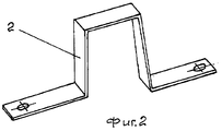
- Фиг.2. П-образный электропроводный режущий элемент со смещенными опорами боковых сторон;- Figure 2. U-shaped conductive cutting element with offset supports of the sides;
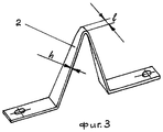
- Фиг.3. V-образный электропроводный режущий элемент;- Figure 3. V-shaped conductive cutting element;
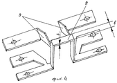
- Фиг.4. П-образный электропроводный режущий элемент с дополнительными опорами;- Figure 4. U-shaped conductive cutting element with additional supports;
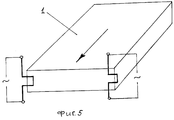
- Фиг.5. Схема работы инструмента.- Figure 5. The scheme of the tool.
Инструмент для безопиловочной резки и получения фигурной поверхности во вспененном материале, например пенополистироле 1, представляет электропроводный режущий элемент 2, изогнутый в виде контура, соответствующего всей или части получаемой конфигурации. В целях исключения деформации электропроводного режущего элемента в процессе работы и повышения его жесткости он выполнен из металлического термостойкого листового материала, например нихрома Х20Н80 или другой марки нержавеющей стали, при этом электропроводный режущий элемент в зоне резания выполнен с соотношением габаритных размеров h:l не менее чем 1:1,6, где нагрев электропроводного режущего элемента осуществляется за счет подачи напряжения к его концам.A tool for sawing and cutting a curved surface in a foam material, for
В зависимости от назначения электропроводный режущий элемент может иметь различную конфигурацию (фиг.1, 2, 4), как, например, П-образную для изготовления пазов и гребней, V-образную (фиг.3) для получения рельефной объемной конфигурации или овальную (не показано).Depending on the purpose, the electrically conductive cutting element may have a different configuration (Figs. 1, 2, 4), such as, for example, U-shaped for the manufacture of grooves and ridges, V-shaped (Fig. 3) to obtain a relief volumetric configuration or oval ( not shown).
Для придания жесткости, увеличения сопротивлению изгибу и деформации электропроводный режущий элемент снабжен дополнительными опорами 3 (фиг.4, фото - Приложение 2), при этом толщина опор не превышает толщины электропроводного режущего элемента.To impart rigidity, increase resistance to bending and deformation, the electrically conductive cutting element is equipped with additional supports 3 (Fig. 4, photo - Appendix 2), while the thickness of the supports does not exceed the thickness of the electrically conductive cutting element.
Дополнительные опоры 3 выполнены за одно целое с электропроводным режущим элементом. Вместе с тем возможно отдельное изготовление дополнительных опор 3 с последующим неподвижным соединением с электропроводным режущим элементом посредством, например, пайки или сварки (не показано).
Опоры электропроводного режущего элемента расположены с задней его стороны по ходу движения обрабатываемой детали для снижения сопротивления движению режущего инструмента или обрабатываемой детали.The supports of the electrically conductive cutting element are located on its rear side in the direction of movement of the workpiece to reduce the resistance to movement of the cutting tool or workpiece.
В целях перераспределения нагрузки на электропроводный режущий элемент 2 (фиг.2) в процессе резания опорная часть одной боковой стороны электропроводного режущего инструмента смещена относительно опорной части другой боковой стороны электропроводного режущего инструмента на величину В в направлении подачи при обработке детали. Величина смещения В определяться исходя из выбранных режимов резания.In order to redistribute the load on the electrically conductive cutting element 2 (FIG. 2) during the cutting process, the supporting part of one side of the electrically conductive cutting tool is shifted relative to the supporting part of the other side of the electrically conductive cutting tool by a value B in the feed direction when machining the part. The amount of displacement B is determined based on the selected cutting conditions.
Инструмент работает следующим образом.The tool works as follows.
Возможны два варианта работы инструмента. Первый, когда неподвижен инструмент, а двигается обрабатываемая деталь, и второй, при котором обрабатываемая деталь неподвижна, а двигается сам инструмент.There are two options for the tool. The first, when the tool is stationary, and the workpiece moves, and the second, in which the workpiece is stationary, and the tool moves.
На фиг.5 представлена схема работы устройства с неподвижным инструментом. Перед началом работы на концы электропроводного режущего элемента подается напряжение. Происходит разогрев инструмента до заданной рабочей температуры, а затем транспортером подается на инструмент обрабатываемая деталь. Нагретый инструмент производит безопиловочное резание и образует в обрабатываемой детали фигурную поверхность (конфигурацию), соответствующую контуру электропроводного режущего элемента.Figure 5 presents a diagram of the operation of the device with a stationary tool. Before starting work, voltage is applied to the ends of the electrically conductive cutting element. The tool is heated to a predetermined operating temperature, and then the workpiece is fed to the tool by a conveyor. The heated tool performs non-sawing cutting and forms a curved surface (configuration) in the workpiece that corresponds to the contour of the electrically conductive cutting element.
Достигнутый технический результат заключается в том, что благодаря изготовлению электропроводного режущего элемента из листового материала с заданным соотношением габаритных размеров его поперечного сечения h:l не менее чем 1:1,6 и введения дополнительных опор значительно возросла жесткость инструмента, повысилась надежность его работы и увеличился срок службы инструмента.The technical result achieved is that due to the manufacture of an electrically conductive cutting element from sheet material with a given ratio of overall dimensions of its cross section h: l of at least 1: 1.6 and the introduction of additional supports, the tool stiffness significantly increased, its reliability increased and increased tool life.
Claims (9)
Priority Applications (1)
| Application Number | Priority Date | Filing Date | Title |
|---|---|---|---|
| RU2005105455/02A RU2289503C2 (en) | 2005-02-28 | 2005-02-28 | Saw-free cutting tool for forming shaped surface in foam material |
Applications Claiming Priority (1)
| Application Number | Priority Date | Filing Date | Title |
|---|---|---|---|
| RU2005105455/02A RU2289503C2 (en) | 2005-02-28 | 2005-02-28 | Saw-free cutting tool for forming shaped surface in foam material |
Publications (1)
| Publication Number | Publication Date |
|---|---|
| RU2289503C2 true RU2289503C2 (en) | 2006-12-20 |
Family
ID=37666971
Family Applications (1)
| Application Number | Title | Priority Date | Filing Date |
|---|---|---|---|
| RU2005105455/02A RU2289503C2 (en) | 2005-02-28 | 2005-02-28 | Saw-free cutting tool for forming shaped surface in foam material |
Country Status (1)
| Country | Link |
|---|---|
| RU (1) | RU2289503C2 (en) |
Cited By (5)
| Publication number | Priority date | Publication date | Assignee | Title |
|---|---|---|---|---|
| MD3840G2 (en) * | 2007-12-21 | 2009-09-30 | Еуджен МОРАРУ | Process for obtaining from a monolithic piece of polymeric material adjacent forms for placement of objects having a complex figure of rotation |
| MD20110031A2 (en) * | 2011-04-11 | 2012-10-31 | А.О.R.I.F. | Permanent shuttering panel and device for its production |
| MD738Z (en) * | 2011-04-11 | 2014-09-30 | А.О.R.I.F. | Permanent shuttering panel and device for its production |
| RU2596516C2 (en) * | 2015-01-29 | 2016-09-10 | Александр Николаевич Мирсков | Cutter for shaped cross-cutting polymer tape |
| US20160375600A1 (en) * | 2015-06-29 | 2016-12-29 | Igor Markovsky | Joint cutting in a device |
Citations (3)
| Publication number | Priority date | Publication date | Assignee | Title |
|---|---|---|---|---|
| SU381550A1 (en) * | 1971-02-24 | 1973-05-22 | Ю. С. Левин, В. П. Фоломеев , Р. М. Анчиполовский Трест Энергомеханизаци | DEVICE FOR CUTTING PLASTIC POLYSTYRENE TYPE |
| SU1666314A1 (en) * | 1988-12-26 | 1991-07-30 | Предприятие П/Я В-8751 | Device for cutting polymer materials |
| WO2004062861A1 (en) * | 2003-01-13 | 2004-07-29 | Peter David Hurley | Method and apparatus for manufacturing a three dimensional element sculpture |
-
2005
- 2005-02-28 RU RU2005105455/02A patent/RU2289503C2/en not_active IP Right Cessation
Patent Citations (3)
| Publication number | Priority date | Publication date | Assignee | Title |
|---|---|---|---|---|
| SU381550A1 (en) * | 1971-02-24 | 1973-05-22 | Ю. С. Левин, В. П. Фоломеев , Р. М. Анчиполовский Трест Энергомеханизаци | DEVICE FOR CUTTING PLASTIC POLYSTYRENE TYPE |
| SU1666314A1 (en) * | 1988-12-26 | 1991-07-30 | Предприятие П/Я В-8751 | Device for cutting polymer materials |
| WO2004062861A1 (en) * | 2003-01-13 | 2004-07-29 | Peter David Hurley | Method and apparatus for manufacturing a three dimensional element sculpture |
Non-Patent Citations (1)
| Title |
|---|
| Инструмент для безопиловочной резки [он-лайн], FOAM CUTTING SYSTEMS GMBH, 23.09.2004 [найдено 11.01.2006]. Найдено из Интернет <URL:http://www.foamcut.com/CD2/English/Machines/index_products_tt880.htm. * |
Cited By (6)
| Publication number | Priority date | Publication date | Assignee | Title |
|---|---|---|---|---|
| MD3840G2 (en) * | 2007-12-21 | 2009-09-30 | Еуджен МОРАРУ | Process for obtaining from a monolithic piece of polymeric material adjacent forms for placement of objects having a complex figure of rotation |
| MD20110031A2 (en) * | 2011-04-11 | 2012-10-31 | А.О.R.I.F. | Permanent shuttering panel and device for its production |
| MD738Z (en) * | 2011-04-11 | 2014-09-30 | А.О.R.I.F. | Permanent shuttering panel and device for its production |
| RU2596516C2 (en) * | 2015-01-29 | 2016-09-10 | Александр Николаевич Мирсков | Cutter for shaped cross-cutting polymer tape |
| US20160375600A1 (en) * | 2015-06-29 | 2016-12-29 | Igor Markovsky | Joint cutting in a device |
| CN106304737A (en) * | 2015-06-29 | 2017-01-04 | 微软技术许可有限责任公司 | Joint cutting in equipment |
Similar Documents
| Publication | Publication Date | Title |
|---|---|---|
| JP3924538B2 (en) | Method and apparatus for manufacturing a curved spring strip section | |
| KR101945091B1 (en) | Bending-press forming punch | |
| CA2962236C (en) | Method of manufacturing press-formed product, and press-formed product | |
| WO2006102089A3 (en) | Precision-folded, high strength, fatigue-resistant structures and sheet therefor | |
| RU2289503C2 (en) | Saw-free cutting tool for forming shaped surface in foam material | |
| WO2015056615A1 (en) | Spring forming device and forming method | |
| CA2880661C (en) | Method of producing steel pipe | |
| JP4362154B2 (en) | Band saw blade | |
| EP1537922B1 (en) | Manufacturing profiles having a cross-section varying in longitudinal direction | |
| JP5517921B2 (en) | Assembly and method for press forming deformable material | |
| CN112570510A (en) | Laser-assisted roll forming method, device and system for reducing part springback | |
| JP2008238276A (en) | Heald support bar made of bent sheet metal | |
| JP2005510361A (en) | Pipe manufacturing equipment | |
| JP6124152B2 (en) | Roll forming machine and roll forming method | |
| JP6059995B2 (en) | Manufacturing method of tubular exterior material and manufacturing method of wire harness | |
| JP4530463B2 (en) | Method and apparatus for manufacturing mesh member | |
| KR20190015464A (en) | Press product manufacturing method | |
| JP4993955B2 (en) | Sipe blade manufacturing method | |
| CN112770852B (en) | Method for manufacturing complex curvature tubular products such as ELM coils | |
| SU566511A3 (en) | Method of making a rigid steel structure | |
| KR101308630B1 (en) | Successive bending work of pipe and method of successive bending work for pipe | |
| KR101322788B1 (en) | Device for bending metal material and method for making flange using the device | |
| CN112839771A (en) | saw wire | |
| JP2010115705A (en) | Method of manufacturing perforated plate and perforated plate | |
| DE602006005011D1 (en) | MACHINE FOR WOVEN, SHAPING, FOLDING OR BENDING OF BARS, WIRES OR EXTRUDED SHAPED BODIES AND THIS INSTALLING PROCESS |
Legal Events
| Date | Code | Title | Description |
|---|---|---|---|
| MM4A | The patent is invalid due to non-payment of fees |
Effective date: 20070301 |