RU2287311C2 - Hanging apparatus with vertical profiled rack and bracket to be hung on bracket - Google Patents
Hanging apparatus with vertical profiled rack and bracket to be hung on bracket Download PDFInfo
- Publication number
- RU2287311C2 RU2287311C2 RU2004117881/12A RU2004117881A RU2287311C2 RU 2287311 C2 RU2287311 C2 RU 2287311C2 RU 2004117881/12 A RU2004117881/12 A RU 2004117881/12A RU 2004117881 A RU2004117881 A RU 2004117881A RU 2287311 C2 RU2287311 C2 RU 2287311C2
- Authority
- RU
- Russia
- Prior art keywords
- profile
- bracket
- sides
- gripping
- hanging
- Prior art date
Links
Images

Classifications
-
- A—HUMAN NECESSITIES
- A47—FURNITURE; DOMESTIC ARTICLES OR APPLIANCES; COFFEE MILLS; SPICE MILLS; SUCTION CLEANERS IN GENERAL
- A47F—SPECIAL FURNITURE, FITTINGS, OR ACCESSORIES FOR SHOPS, STOREHOUSES, BARS, RESTAURANTS OR THE LIKE; PAYING COUNTERS
- A47F5/00—Show stands, hangers, or shelves characterised by their constructional features
- A47F5/08—Show stands, hangers, or shelves characterised by their constructional features secured to the wall, ceiling, or the like; Wall-bracket display devices
- A47F5/0807—Display panels, grids or rods used for suspending merchandise or cards supporting articles; Movable brackets therefor
- A47F5/0838—Rails or bars; Article supports therefor, e.g. brackets being slidably attached on the outside thereof
-
- A—HUMAN NECESSITIES
- A47—FURNITURE; DOMESTIC ARTICLES OR APPLIANCES; COFFEE MILLS; SPICE MILLS; SUCTION CLEANERS IN GENERAL
- A47F—SPECIAL FURNITURE, FITTINGS, OR ACCESSORIES FOR SHOPS, STOREHOUSES, BARS, RESTAURANTS OR THE LIKE; PAYING COUNTERS
- A47F5/00—Show stands, hangers, or shelves characterised by their constructional features
- A47F5/10—Adjustable or foldable or dismountable display stands
- A47F5/101—Display racks with slotted uprights
Abstract
Description
Настоящее изобретение относится к устройству для подвешивания с профилированной рейкой для вертикального размещения на опорной структуре, как, например, задней стенке, панели, раме или каркасе, и кронштейном, навешиваемым на профилированную рейку. Профилированная рейка имеет растр, в котором можно подвешивать кронштейн, который соединен с консолью, поперечиной или балкой типа плиты. Конструкции, образованные отрезками профилированной рейки, могут применяться, например, как информационные и декоративные стенды в приемных или как подставки для презентации товаров или экспонатов или для хранения предметов.The present invention relates to a device for hanging with a profiled rail for vertical placement on a supporting structure, such as, for example, a rear wall, panel, frame or frame, and a bracket mounted on a profiled rail. The profiled rail has a raster in which it is possible to suspend a bracket that is connected to a console, a cross member or a beam such as a plate. Structures formed by sections of profiled slats can be used, for example, as information and decorative stands in reception rooms or as stands for the presentation of goods or exhibits or for storing items.
Известны разнообразные устройства для точечной подвески (например, ЕР 0716825 B1; WO 99/20094; DE 20109028 U1). Устройства для подвешивания в различных формах исполнения предлагались также для переменного по горизонтали расположения консолей (например, WO 99/65368; WO 01/43599). Наконец, известно много вариантов устройств для подвешивания для переменного по вертикали расположения профилированных реек и навешиваемых на них кронштейнов (например, DE 20100181 U1).A variety of devices for point suspension are known (e.g., EP 0716825 B1; WO 99/20094; DE 20109028 U1). Suspension devices in various forms of execution have also been proposed for the horizontal arrangement of consoles (for example, WO 99/65368; WO 01/43599). Finally, there are many options for hanging devices for vertically variable arrangement of profiled rails and brackets hanging on them (for example, DE 20100181 U1).
Устройства, известные из уровня техники, оправдали себя в прошлом. Однако остаются потребности в усовершенствовании, т.е. повышение стабильности, возможность модификации, удобство обслуживания и целесообразность, а также в новых решениях, которые открывают дальнейшие возможности конструктивного оформления.Devices known in the art have paid off in the past. However, there remains a need for improvement, i.e. increased stability, the possibility of modification, ease of maintenance and expediency, as well as in new solutions that open up further possibilities for design.
Ввиду этого в основе изобретения стоит задача предложить улучшенное и оригинальное устройство для подвешивания с повышенными потребительскими свойствами для определенной выше области применения, которое состоит из профилированной рейки для вертикальной установки на опорной структуре и подвешенного на профилированной рейке кронштейна. Должно быть возможным подвешивать на профилированной рейке несколько кронштейнов на различной высоте, соединять кронштейны с различным образом конфигурированными несущими стойками и устанавливать профилированные рейки как в вертикальные линии, с различными длинами, в зависимости от локальных условий, так и располагать их как короткие отрезки.In view of this, the invention is based on the task of proposing an improved and original device for hanging with improved consumer properties for the above-defined field of application, which consists of a profiled rail for vertical installation on a supporting structure and a bracket suspended on a profiled rail. It should be possible to suspend several brackets on a profiled rail at different heights, connect the brackets with variously configured supporting racks and install the profiled rails both in vertical lines, with different lengths, depending on local conditions, and arrange them as short segments.
Поставленная задача в устройстве для подвешивания, состоящем из располагаемого вертикально профиля с лицевой стороной, двумя боковыми сторонами и задней стороной, а также имеющегося у профиля контура захвата; и навешиваемого на профиль кронштейна с дополняющими контуры захвата фиксирующими элементами; и кронштейн охватывает лицевую сторону, а также обе боковые стороны профиля, согласно изобретению решается тем, что фиксирующие элементы расположены на имеющей вид скобок части охватывающей части кронштейна, или на пружине, или выполнены обладающими собственной упругостью; и контуры захвата в профиле расположены в боковых сторонах профиля и заглублены относительно лицевой стороны.The task in the device for hanging, consisting of a vertically arranged profile with a front side, two sides and a back side, as well as the capture contour of the profile; and a bracket hinged on the profile with fixing elements complementary to the gripping contours; and the bracket covers the front side, as well as both sides of the profile, according to the invention, it is decided that the locking elements are located on the bracket-shaped part of the female bracket part, or on the spring, or are made having their own elasticity; and the gripping contours in the profile are located on the sides of the profile and are recessed relative to the front side.
Контуры захвата образованы как заглубленные относительно лицевой стороны клиновидные прорези в боковых сторонах, снизу имеют выступ в виде карниза и постепенно сближаются, предпочтительно в наклонной плоскости, поднимаясь к плоскости боковых сторон.The gripping contours are formed as wedge-shaped slots recessed relative to the front side in the sides, have a ledge in the form of a cornice from below, and gradually come together, preferably in an inclined plane, rising to the plane of the sides.
Контуры захвата на одной из боковых сторон расположены симметрично контурам захвата на другой боковой стороне; фиксирующий элемент в кронштейне является соответственно установленным на пружине клином, причем пружины и клинья предусмотрены соответственно по обеим сторонам паза, принимающего профиль; и пружины, и клинья взаимно удерживают друг друга.The gripping contours on one of the sides are symmetrical to the gripping contours on the other side; the fixing element in the bracket is respectively a wedge mounted on the spring, the springs and wedges provided respectively on both sides of the groove receiving the profile; and springs and wedges mutually hold each other.
Профиль состоит из задней рейки с контурами захвата, которая предпочтительно является пластмассовой, и передней рейки; и профиль используется как цельная стойка или в виде коротких отрезков, по меньшей мере, с одной парой контуров захвата.The profile consists of a rear rail with gripping contours, which is preferably plastic, and a front rail; and the profile is used as an entire rack or in the form of short segments with at least one pair of gripping contours.
Благодаря изобретению в распоряжении имеется теперь новое устройство для подвешивания в различных вариантах с расположенной вертикально профилированной рейкой и в зависимости от продольного сечения несколькими навешиваемыми на нее кронштейнами. Этим открываются более широкие оригинальные возможности оформления при эффективной стоимости изготовления и монтажа.Thanks to the invention, a new suspension device is now available in various versions with a vertically profiled rail and, depending on the longitudinal section, several brackets hanging on it. This opens up wider original design possibilities at an effective cost of manufacture and installation.
На прилагаемых чертежах показано:The accompanying drawings show:
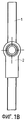
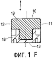
фиг.1А - устройство для подвешивания, с профилем, который снабжен сбоку заглубленным относительно лицевой стороны щелевым растром, и измененным кронштейном, в навешенном состоянии, вид в перспективе;figa is a device for hanging, with a profile, which is provided on the side with a slotted raster recessed relative to the front side, and a modified bracket, in hinged condition, perspective view;
фиг.1В - устройство по фиг.1А, вид спереди;figv - the device of figa, front view;
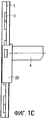
фиг.1C - устройство по фиг.1А, вид сбоку;figs - the device of figa, side view;
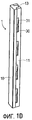
фиг.1D - профиль по фиг.1А;fig.1D - profile of figa;
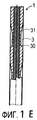
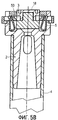
фиг.1Е - профиль по фиг.1А, вертикальный разрез;figa - profile of figa, a vertical section;
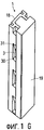
фиг.1F - профиль по фиг.1G, в увеличенном горизонтальном разрезе;fig.1F - profile of fig.1G, in an enlarged horizontal section;
фиг.1G - профиль по фиг.1А, с резьбовым соединением на задней стороне;figg - profile of figa, with a threaded connection on the rear side;
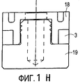
фиг.1Н - профиль по фиг.1G, в увеличенном горизонтальном разрезе;fign - profile according figg, in an enlarged horizontal section;
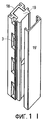
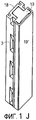
фиг.1I - профиль по фиг.1А, с винтовым соединением на лицевой стороне, с отделенным декоративным покрытием;figa - profile of figa, with a screw connection on the front side, with a separated decorative coating;
фиг.1J - расположение согласно фиг.1I, с декоративным покрытием, надетым на профиль;fig.1J - the location according to fig.1I, with a decorative coating worn on the profile;
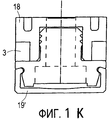
фиг.1К - профиль согласно фиг.1J, в увеличенном горизонтальном разрезе;figk - profile according fig.1J, in an enlarged horizontal section;
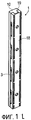
фиг.1L - вид в перспективе профиля по фиг.1D, вид сзади;figl is a perspective view of the profile of fig.1D, rear view;
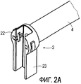
фиг.2А - кронштейн согласно фиг.1А, вид сзади в перспективе;figa - bracket according figa, rear view in perspective;
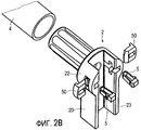
фиг.2В - кронштейн согласно фиг.2А, в разобранном виде;figv - bracket according figa, disassembled;
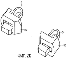
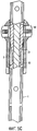
фиг.2С - положение пружин и клиньев для кронштейна согласно фиг.2А, с кронштейном, зажатым в профиле;figs - the position of the springs and wedges for the bracket according to figa, with the bracket clamped in the profile;
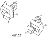
фиг.2D - положение пружин и клиньев для кронштейна согласно фиг.2А, с кронштейном в свободном положении у профиля;fig.2D - the position of the springs and wedges for the bracket according to figa, with the bracket in the free position at the profile;
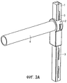
фиг.3А - расположение согласно фиг.1А, в положении фиксации, вид в перспективе;figa - arrangement according figa, in the position of fixation, perspective view;
фиг.3В - расположение согласно фиг.3А, в увеличенном горизонтальном разрезе;figv - arrangement according figa, in an enlarged horizontal section;
фиг.4А - расположение согласно фиг.1А, в положении скольжения, в увеличенном горизонтальном разрезе;figa - arrangement according figa, in the sliding position, in an enlarged horizontal section;
фиг.4В - расположение согласно фиг.4А, вертикальный разрез;figv - arrangement according figa, a vertical section;
фиг.5А - расположение согласно фиг.1А, в свободном положении, вид в перспективе;figa - arrangement according figa, in a free position, a perspective view;
фиг.5В - расположение согласно фиг.5А, в увеличенном горизонтальном разрезе;figv - arrangement according figa, in an enlarged horizontal section;
фиг.5С - расположение согласно фиг.5А, в увеличенном вертикальном разрезе;figs - the location according to figa, in an enlarged vertical section;
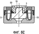
фиг.6А - расположение согласно фиг.1А, с универсальным кронштейном, в положении фиксации, вид в перспективе;figa - arrangement according figa, with a universal bracket, in the locked position, perspective view;
фиг.6В - расположение согласно фиг.6А, вид сверху;figv - arrangement according figa, top view;
фиг.6С - расположение согласно фиг.6А, в увеличенном горизонтальном разрезе;figs - arrangement according figa, in an enlarged horizontal section;
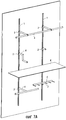
фиг.7А - панель с устройством для подвешивания согласно фиг.1А и различно конфигурированными несущими рейками;figa - panel with a device for hanging according to figa and variously configured supporting rails;
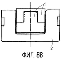
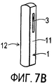
фиг.7В - часть профиля устройства по фиг.1А с парой пазов;figv - part of the profile of the device of figa with a pair of grooves;
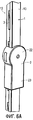
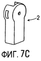
фиг.7С - универсальный кронштейн согласно фиг.6А;figs - universal bracket according figa;
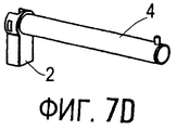
фиг.7D - кронштейн с прямым плечом;fig.7D - bracket with a straight shoulder;
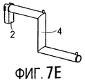
фиг.7Е - кронштейн со ступенчатым плечом;fige - bracket with a stepped shoulder;
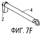
фиг.7F - кронштейн с плечом для поддержки перекладины;Fig.7F - bracket with a shoulder to support the crossbar;
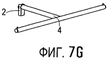
фиг.7G - кронштейн с Т-образным плечом;7G is a bracket with a T-shaped shoulder;
фиг.7Н - кронштейн с планкой с крючками;fign - bracket with strap with hooks;
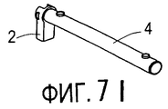
фиг.7I - кронштейн для удержания доски.7I is a bracket for holding the board.
Далее с привлечением приложенных чертежей следует детальное описание примеров исполнения соответствующего изобретению устройства для подвешивания в различных модификациях.Further, with the attached drawings, a detailed description of examples of the execution of the device for hanging in accordance with the invention in various modifications follows.
Для всего дальнейшего описания справедливы следующие утверждения. Если на какой-то фигуре в целях графической однозначности имеется обозначение, но в относящемся к ней непосредственно описании оно не объясняется, это означает, что оно упоминалось в описании предшествующих фигур. Для наглядности в большинстве случаев отказываются от повторного обозначения конструктивных элементов в следующих фигурах, если из чертежей понятно, что речь идет о "повторяющихся" конструктивных элементах.The following statements are true for the entire description that follows. If, for the purpose of graphic uniqueness, there is a designation on some figure, but it is not explained in the description directly, it means that it was mentioned in the description of the previous figures. For clarity, in most cases they refuse to re-designate structural elements in the following figures, if it is clear from the drawings that we are talking about "repeating" structural elements.
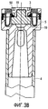
На фиг.1А-1L показан профиль 1 с заглубленным относительно лицевой стороны 10 щелевым растром 3. Щелевой растр 3 расположен на обеих боковых сторонах 11, 12 симметрично друг относительно друга, так что образуются пары прорезей, у которых каждая из прорезей находится на одинаковой высоте. Систематизированные по парам прорези 3 имеют снизу выступ в виде карниза 30, а сверху наклонную площадку 31 на плоскости боковых сторон 11, 12. Особенно выгодно выполнить профиль 1 из двух деталей, а именно с задней рейкой 18 из пластмассы, в которой можно удобно сделать прорези 3, и передней рейкой 19, например, из алюминия, которая накрывает заднюю рейку 18 до щелевого растра 3, благодаря чему его контур получается невидимым. Обе рейки 18, 19 соединяются путем геометрического замыкания. Правильное направление монтажа могла бы, например, показывать разметка стрелками на задней рейке 18. Один вариант осуществления профиля 1 предусмотрен для заднего свинчивания - насквозь через заднюю рейку 18 (см. фиг.1F-1H). Другой вариант выполнения профиля 1 служит для фронтального свинчивания - насквозь через переднюю рейку 19, причем в этом случае для накрывания отверстий под винт и головок винта имеется декоративная планка 19' (см. фиг.1I-1K). Кронштейн 2 с установленной на нем несущей рейкой 4 имеет также охватывающую часть 20 с верхней частью в виде скобок 22 и идущей от нее вниз опорной частью 23.On figa-1L shows a
Кронштейн 2 согласно фиг.2А-2С имеет П-образный идущий вертикально вниз и дополнительный к поперечному сечению профиля 1 паз, чтобы при навешенном кронштейне 2 охватывать им профиль 1, включая его лицевую сторону 10 и обе боковые стороны 11, 12. В расположенной выше части в виде скобок 22 кронштейна 2 с обеих сторон от паза находятся установленные на пружинах 5, ограничено подвижные вбок клинья 50, которые предусмотрены для упругого зацепления в выбранной паре прорезей 3. Пружины 5 вызывают направленное друг на друга предварительное напряжение клиньев 50, острия которых в положении покоя вдаются внутрь паза. Клинья 50 и пружины являются отдельными конструктивными элементами, которые, будучи использованы в скобках 22, взаимно удерживают друг друга.The
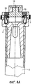
Если кронштейн 2 навешен на профиль 1 в выбранной высоте согласно порядку и грузоподъемности (это состояние определяется как положение фиксации), клинья 50 выдвинуты пружинами 5 в пару прорезей 3 и садятся на грани 30 обеих прорезей 3. Вертикальный компонент нагрузки, который действует от навешенного кронштейна 2 на несущий профиль 1, будет приниматься клиньями 50, вдвинутыми в пару прорезей 3. Направленные вниз наклонные составляющие нагрузки воспринимаются опорной частью 23 и сторонами клиньев 50. Клинья 50 существенно приблизились друг к другу, и опускание кронштейна 2 блокировано (см. фиг.3С, 3А и 3В).If the
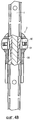
До того, как перейти в положение фиксации, или при выходе из него кронштейн 2 находится в положении скольжения (см. фиг.4А и 4В). Если висящий на профиле 1 кронштейн 2 поднят вверх, клинья 50 начинают подниматься вдоль на наклонных площадках 31 занятой пары прорезей 3 и будут при этом против натяжения пружины 5 выталкиваться наружу, открытыми почти последовательно с поднятием и выходом из пары прорезей 3.Before moving to the locked position, or when exiting from it, the
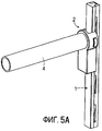
При дальнейшем поднятии навешенного на профиль 1 кронштейна 2 и увеличивающемся при этом выходе из первоначально занятой пары прорезей 3 будет достигнуто наконец свободное положение кронштейна 2 (см. фиг.2Д, 5А-5С). Клинья 50 полностью вышли из пары прорезей 3, достигли максимального размыкания между собой и сидят теперь на боковых сторонах 11, 12 профиля 1. Здесь кронштейн 2 может быть снят с профиля 1 и сдвигаться дальше вверх или вниз до новой фиксации в первоначально занятой паре прорезей 3.With further raising of the
В разделенном положении кронштейн 2 снят с профиля 1; клинья 50 вдвинуты пружинами 5 максимально до границ в паз и находятся там теперь на минимальном расстоянии друг от друга (см. фиг.2А). Благодаря скосам на клиньях 50 кронштейн 2 может навешиваться на профиль 1 на любой высоте.In the divided position, the
Профиль 1 по фиг.6А-7I, составленный из задней рейки 18 с щелевым растром 3 и передней рейки, рассматривается как особенно благоприятный. Показанный на фиг.6А-6С, навешенный на профиль 1 кронштейн 2 может комбинироваться с различно конфигурированными несущими рейками 4, как показано на фиг.7А и 7D-7I.
Для специальных конструкций и применений можно закреплять короткие части профиля 1 на какой-либо опорной структуре. Такие участки должны иметь, по меньшей мере, одну пару лежащих друг против друга прорезей 3. На подобных участках профиля 1 также можно навешивать кронштейны 2, причем здесь вертикальное перемещение по высоте отсутствует (см. фиг.7В и 7С).For special designs and applications, it is possible to fasten the short parts of
Claims (5)
Applications Claiming Priority (2)
| Application Number | Priority Date | Filing Date | Title |
|---|---|---|---|
| CH21052001 | 2001-11-15 | ||
| CH2105/01 | 2001-11-15 |
Publications (2)
| Publication Number | Publication Date |
|---|---|
| RU2004117881A RU2004117881A (en) | 2005-10-27 |
| RU2287311C2 true RU2287311C2 (en) | 2006-11-20 |
Family
ID=4567529
Family Applications (1)
| Application Number | Title | Priority Date | Filing Date |
|---|---|---|---|
| RU2004117881/12A RU2287311C2 (en) | 2001-11-15 | 2002-11-14 | Hanging apparatus with vertical profiled rack and bracket to be hung on bracket |
Country Status (15)
| Country | Link |
|---|---|
| US (1) | US7571882B2 (en) |
| EP (1) | EP1312287B1 (en) |
| JP (1) | JP4421296B2 (en) |
| CN (1) | CN100393261C (en) |
| AT (1) | ATE318092T1 (en) |
| BR (1) | BRPI0214223A2 (en) |
| CA (1) | CA2466512C (en) |
| CY (1) | CY1105558T1 (en) |
| DE (2) | DE50205870D1 (en) |
| DK (1) | DK1312287T5 (en) |
| ES (1) | ES2257526T3 (en) |
| HK (1) | HK1056106A1 (en) |
| PT (1) | PT1312287E (en) |
| RU (1) | RU2287311C2 (en) |
| WO (1) | WO2003041540A1 (en) |
Families Citing this family (46)
| Publication number | Priority date | Publication date | Assignee | Title |
|---|---|---|---|---|
| SE520476C2 (en) * | 2002-02-21 | 2003-07-15 | Hl Display Ab | Device for product exposure spear |
| JP3919705B2 (en) * | 2003-06-27 | 2007-05-30 | 株式会社玉俊工業所 | Base structure of the shelf board |
| JP3742407B2 (en) | 2003-06-27 | 2006-02-01 | 株式会社玉俊工業所 | Base structure of the shelf board |
| US8225946B2 (en) | 2006-06-29 | 2012-07-24 | Simplehuman, Llc | Shelving system |
| DE102007022679B4 (en) * | 2007-05-11 | 2009-04-23 | Wanzl Metallwarenfabrik Gmbh | Market stalls |
| JP2009072393A (en) * | 2007-09-21 | 2009-04-09 | Sanuki:Kk | Shelf board support device |
| WO2009073989A1 (en) * | 2007-12-11 | 2009-06-18 | Visplay International Ag | Suspension device comprising a profiled vertical prop and a primary support that can be hooked thereto |
| US20090188880A1 (en) * | 2008-01-28 | 2009-07-30 | Simplehuman, Llc | Shelving system |
| DK200800111A (en) * | 2008-01-29 | 2009-07-30 | Containersign V Anders Waesel | A sign for affixing to a post of a container |
| US7938373B2 (en) * | 2008-02-13 | 2011-05-10 | Evapco, Inc. | Vertical support structure |
| US7963492B2 (en) * | 2008-02-19 | 2011-06-21 | Evapco, Inc. | Vertical support structure |
| US20100127141A1 (en) * | 2008-07-17 | 2010-05-27 | Herman Chan | Slotted Toolless Bracket for PDU |
| US20110215212A1 (en) * | 2008-11-14 | 2011-09-08 | Aydin Keyvanloo | Vertical mounting system |
| US8474632B2 (en) | 2008-12-01 | 2013-07-02 | Simplehuman, Llc | Shelving system |
| USD622990S1 (en) | 2009-03-20 | 2010-09-07 | Simplehuman, Llc | Shelving system |
| JP5215252B2 (en) * | 2009-06-29 | 2013-06-19 | ダイワラクダ工業株式会社 | Pipe socket |
| US8251324B2 (en) | 2009-09-23 | 2012-08-28 | Liberty Hardware Mfg. Corp. | Support arm positioning tab |
| USD628841S1 (en) | 2009-12-01 | 2010-12-14 | Simplehuman, Llc | Shelving system |
| US8424241B2 (en) * | 2009-12-24 | 2013-04-23 | George M. Schaeffer | Trellising cross arm |
| USD651838S1 (en) | 2010-03-12 | 2012-01-10 | Simplehuman, Llc | Shelving system |
| USD651837S1 (en) | 2010-03-12 | 2012-01-10 | Simplehuman, Llc | Shelving system |
| US9307848B2 (en) | 2012-08-28 | 2016-04-12 | David Bernstein | Product display system |
| US8814108B2 (en) | 2012-08-28 | 2014-08-26 | David Bernstein | Product display system |
| DE202012008735U1 (en) | 2012-09-12 | 2012-10-18 | Visplay International Ag | Hanging device for presenting goods with a mountable on a support structure holder can be suspended therein primary carrier |
| CN104729218A (en) * | 2013-12-23 | 2015-06-24 | 海尔集团公司 | Adjustable shelf and refrigeration equipment |
| DE102014202699A1 (en) | 2014-02-14 | 2015-08-20 | Visplay International Ag | Suspension device for the presentation of goods |
| USD727060S1 (en) | 2014-03-12 | 2015-04-21 | Simplehuman, Llc | Shelving system |
| USD726441S1 (en) | 2014-03-12 | 2015-04-14 | Simplehuman, Llc | Shelving system |
| US9339151B2 (en) | 2014-03-13 | 2016-05-17 | Simplehuman, Llc | Shelving system with obscurable shelving |
| USD734956S1 (en) | 2014-03-13 | 2015-07-28 | Simplehuman, Llc | Shelving system |
| US9943192B2 (en) | 2014-03-13 | 2018-04-17 | Simplehuman, Llc | Shelving system with obscurable shelving |
| US9883742B2 (en) | 2014-03-14 | 2018-02-06 | Simplehuman, Llc | Shower caddy with shelf adjustably maounted along an elongate support member |
| US9487960B2 (en) | 2014-06-17 | 2016-11-08 | One Energy Enterprises Llc | Suspended deck systems, kits, and methods of installing, inspecting, and repairing a suspended deck system |
| CN104473437B (en) * | 2014-12-15 | 2016-05-18 | 尹宏 | A kind of Suspended table with top of variable height panel assembly |
| USD769641S1 (en) | 2015-02-23 | 2016-10-25 | Simplehuman, Llc | Shower caddy |
| USD770197S1 (en) | 2015-02-23 | 2016-11-01 | Simplehuman, Llc | Shower caddy |
| USD770198S1 (en) | 2015-02-25 | 2016-11-01 | Simplehuman, Llc | Shelving system |
| USD766688S1 (en) * | 2015-03-04 | 2016-09-20 | Lifetime Brands, Inc. | Corkscrew |
| CN104816869B (en) * | 2015-04-23 | 2017-01-25 | 中车眉山车辆有限公司 | Double-contact tray bearing seat |
| USD800396S1 (en) * | 2015-10-23 | 2017-10-17 | Andrew G. Coviello | Adjustable height pet feeder |
| CN105470756B (en) * | 2015-11-13 | 2019-01-11 | 厦门上特展示系统工程有限公司 | Hang electrified system |
| USD824189S1 (en) | 2017-02-23 | 2018-07-31 | Simplehuman, Llc | Shower caddy |
| PL3403526T3 (en) * | 2017-05-15 | 2020-05-18 | Peka-Metall Ag | Shelf |
| US10921050B1 (en) * | 2019-10-10 | 2021-02-16 | Whirlpool Corporation | Support assembly for appliance |
| US20210169278A1 (en) * | 2019-12-09 | 2021-06-10 | Mitchell April M | Organizer system and method of use |
| CN113775901B (en) * | 2020-06-10 | 2022-11-04 | 启碁科技股份有限公司 | Suspension type fixing seat and bracket unit thereof |
Family Cites Families (24)
| Publication number | Priority date | Publication date | Assignee | Title |
|---|---|---|---|---|
| US2026223A (en) * | 1933-06-27 | 1935-12-31 | Frank A Donnelly | Shelving |
| US2229473A (en) * | 1939-03-04 | 1941-01-21 | Norman W Redmer | Tripod |
| FR945260A (en) * | 1945-03-03 | 1949-04-29 | Church & Company Fittings Ltd | Cleat for supporting wall shelves, shelves or the like |
| US2872144A (en) * | 1952-10-28 | 1959-02-03 | Nancy Hobson | Adjustable bracket supports for display and other purposes |
| USRE27200E (en) * | 1968-04-24 | 1971-10-26 | Steel shelving | |
| US3512654A (en) * | 1968-05-09 | 1970-05-19 | Jarke Corp | Modular cantilever adjustable arm rack and joint assembly |
| US3794183A (en) * | 1971-07-06 | 1974-02-26 | Rack Eng Co | Adjustable storage rack |
| US3854686A (en) * | 1972-06-21 | 1974-12-17 | Speedrack Inc | Cantilever rack |
| US4205629A (en) * | 1978-04-24 | 1980-06-03 | Wix Thomas R | Adjustable height bowl holding apparatus |
| US4348989A (en) * | 1980-02-25 | 1982-09-14 | Vik Darrell D | Adjustable waterer |
| US4444323A (en) * | 1981-05-11 | 1984-04-24 | Travis Handling Systems, Inc. | Retaining means for adjustable cantilever storage racks |
| US4553726A (en) * | 1983-09-19 | 1985-11-19 | Ex-Cell-O Corporation | Adjustable height seat apparatus for combat vehicle |
| DE3334709C2 (en) * | 1983-09-24 | 1985-07-25 | Jean Walterscheid Gmbh, 5204 Lohmar | Telescopic shaft |
| GB2154429A (en) | 1984-02-27 | 1985-09-11 | Pioneer Seed Company | Shelving system |
| CN2113664U (en) * | 1992-01-28 | 1992-08-26 | 陈博文 | Frame combination rack |
| ATE163515T1 (en) | 1994-12-13 | 1998-03-15 | Fehlbaum & Co | SUPPORT ROD ARRANGEMENT FOR HANGING GOODS TO BE DISPLAYED OR FOR HOLDING A GOODS SHELF |
| EP0941680A1 (en) | 1998-03-13 | 1999-09-15 | Fehlbaum & Co. | Article hanger hook system for commercial and institutional services |
| EP0965296A1 (en) | 1998-06-18 | 1999-12-22 | Fehlbaum & Co. | Article display device |
| AU6362100A (en) | 1999-07-23 | 2001-02-13 | Children's Hospital Of Philadelphia, The | Derivatized polyurethane compositions and methods of making |
| FR2796820B1 (en) * | 1999-07-28 | 2001-10-19 | Grosfillex Sarl | CONSOLE SHELF SUPPORT DEVICE |
| DE29922163U1 (en) | 1999-12-17 | 2000-02-17 | Fehlbaum & Co | Arrangement for hanging articles or for holding a shelf |
| DE20009028U1 (en) | 2000-05-19 | 2000-08-03 | Vitrashop Patente Ag Muttenz | Support rod arrangement |
| DE20100181U1 (en) | 2001-01-06 | 2001-06-13 | Visplay Ip Ag Muttenz | Profile for vertical arrangement and for hanging consoles |
| DE20109028U1 (en) | 2001-05-30 | 2001-08-23 | Wiedner Klaus | glasses |
-
2002
- 2002-11-14 BR BRPI0214223A patent/BRPI0214223A2/en not_active IP Right Cessation
- 2002-11-14 AT AT02405981T patent/ATE318092T1/en active
- 2002-11-14 JP JP2003543438A patent/JP4421296B2/en not_active Expired - Lifetime
- 2002-11-14 DE DE50205870T patent/DE50205870D1/en not_active Expired - Lifetime
- 2002-11-14 RU RU2004117881/12A patent/RU2287311C2/en not_active IP Right Cessation
- 2002-11-14 EP EP02405981A patent/EP1312287B1/en not_active Expired - Lifetime
- 2002-11-14 ES ES02405981T patent/ES2257526T3/en not_active Expired - Lifetime
- 2002-11-14 WO PCT/CH2002/000612 patent/WO2003041540A1/en active Application Filing
- 2002-11-14 CA CA002466512A patent/CA2466512C/en not_active Expired - Fee Related
- 2002-11-14 US US10/495,296 patent/US7571882B2/en not_active Expired - Lifetime
- 2002-11-14 PT PT02405981T patent/PT1312287E/en unknown
- 2002-11-14 DK DK02405981T patent/DK1312287T5/en active
- 2002-11-14 CN CNB028252438A patent/CN100393261C/en not_active Expired - Fee Related
- 2002-11-15 DE DE20217715U patent/DE20217715U1/en not_active Expired - Lifetime
-
2003
- 2003-11-20 HK HK03108452A patent/HK1056106A1/en not_active IP Right Cessation
-
2006
- 2006-05-04 CY CY20061100576T patent/CY1105558T1/en unknown
Also Published As
| Publication number | Publication date |
|---|---|
| JP4421296B2 (en) | 2010-02-24 |
| RU2004117881A (en) | 2005-10-27 |
| BRPI0214223A2 (en) | 2016-06-28 |
| CY1105558T1 (en) | 2010-07-28 |
| CA2466512C (en) | 2008-07-29 |
| DE20217715U1 (en) | 2003-02-20 |
| ATE318092T1 (en) | 2006-03-15 |
| US20050040301A1 (en) | 2005-02-24 |
| WO2003041540A1 (en) | 2003-05-22 |
| ES2257526T3 (en) | 2006-08-01 |
| CN100393261C (en) | 2008-06-11 |
| DE50205870D1 (en) | 2006-04-27 |
| DK1312287T5 (en) | 2006-07-17 |
| PT1312287E (en) | 2006-06-30 |
| EP1312287B1 (en) | 2006-02-22 |
| DK1312287T3 (en) | 2006-06-26 |
| HK1056106A1 (en) | 2004-02-06 |
| EP1312287A1 (en) | 2003-05-21 |
| JP2005508685A (en) | 2005-04-07 |
| US7571882B2 (en) | 2009-08-11 |
| CN1604748A (en) | 2005-04-06 |
| CA2466512A1 (en) | 2003-05-22 |
Similar Documents
| Publication | Publication Date | Title |
|---|---|---|
| RU2287311C2 (en) | Hanging apparatus with vertical profiled rack and bracket to be hung on bracket | |
| RU2579735C2 (en) | Wall structures for storage | |
| US9468312B2 (en) | Display fixture with cantilevered shelf | |
| US6497185B1 (en) | Slidable unit for modular shelving system | |
| RU2082307C1 (en) | Shelving and window store system | |
| US7296697B2 (en) | Adjustable closet organizer system | |
| US5938048A (en) | Modular tiered rack assembly | |
| US4655352A (en) | Expandable display rack frame | |
| EP3599937B1 (en) | Drawer for wall mounted storage system | |
| US7104411B2 (en) | System for detachable suspension of shelves, drawers or the like | |
| NL8320397A (en) | METHOD FOR BUILDING A BEARING PANEL WALL AND A PROFILE PART FOR USE IN THE METHOD | |
| WO2000067237A2 (en) | Modular display system | |
| CA2857130A1 (en) | Double end frame | |
| JPH03114411A (en) | Article-showing system | |
| US4984694A (en) | Combined string basket and string shelf system | |
| US4446669A (en) | End channel member for space dividing system panel | |
| US5562333A (en) | Bracket for use in a cabinet or similar furniture article with a false drawer front and with a drawer guide having a tongue portion | |
| GB2397012A (en) | Adjustable display system | |
| JP4388507B2 (en) | Storage rack | |
| US4887873A (en) | File system with hang rail | |
| KR102302530B1 (en) | Dishes Shelf for Window Frame | |
| GB2090121A (en) | Shelf support system | |
| JP3728037B2 (en) | Slide bookshelf | |
| JP3500978B2 (en) | Mounting structure for hanging shelves | |
| KR20210054973A (en) | Shelf for Dishes |
Legal Events
| Date | Code | Title | Description |
|---|---|---|---|
| MM4A | The patent is invalid due to non-payment of fees |
Effective date: 20191115 |