JP4421296B2 - Suspension device with molded rails to be placed vertically and brackets that can be hooked to them - Google Patents
Suspension device with molded rails to be placed vertically and brackets that can be hooked to them Download PDFInfo
- Publication number
- JP4421296B2 JP4421296B2 JP2003543438A JP2003543438A JP4421296B2 JP 4421296 B2 JP4421296 B2 JP 4421296B2 JP 2003543438 A JP2003543438 A JP 2003543438A JP 2003543438 A JP2003543438 A JP 2003543438A JP 4421296 B2 JP4421296 B2 JP 4421296B2
- Authority
- JP
- Japan
- Prior art keywords
- bracket
- spring
- engagement contour
- molded
- suspension device
- Prior art date
- Legal status (The legal status is an assumption and is not a legal conclusion. Google has not performed a legal analysis and makes no representation as to the accuracy of the status listed.)
- Expired - Lifetime
Links
Images


Classifications
-
- A—HUMAN NECESSITIES
- A47—FURNITURE; DOMESTIC ARTICLES OR APPLIANCES; COFFEE MILLS; SPICE MILLS; SUCTION CLEANERS IN GENERAL
- A47F—SPECIAL FURNITURE, FITTINGS, OR ACCESSORIES FOR SHOPS, STOREHOUSES, BARS, RESTAURANTS OR THE LIKE; PAYING COUNTERS
- A47F5/00—Show stands, hangers, or shelves characterised by their constructional features
- A47F5/08—Show stands, hangers, or shelves characterised by their constructional features secured to the wall, ceiling, or the like; Wall-bracket display devices
- A47F5/0807—Display panels, grids or rods used for suspending merchandise or cards supporting articles; Movable brackets therefor
- A47F5/0838—Rails or bars; Article supports therefor, e.g. brackets being slidably attached on the outside thereof
-
- A—HUMAN NECESSITIES
- A47—FURNITURE; DOMESTIC ARTICLES OR APPLIANCES; COFFEE MILLS; SPICE MILLS; SUCTION CLEANERS IN GENERAL
- A47F—SPECIAL FURNITURE, FITTINGS, OR ACCESSORIES FOR SHOPS, STOREHOUSES, BARS, RESTAURANTS OR THE LIKE; PAYING COUNTERS
- A47F5/00—Show stands, hangers, or shelves characterised by their constructional features
- A47F5/10—Adjustable or foldable or dismountable display stands
- A47F5/101—Display racks with slotted uprights
Landscapes
- Clamps And Clips (AREA)
- Supports Or Holders For Household Use (AREA)
- Load-Engaging Elements For Cranes (AREA)
- Chain Conveyers (AREA)
- Mirrors, Picture Frames, Photograph Stands, And Related Fastening Devices (AREA)
- Vehicle Step Arrangements And Article Storage (AREA)
- Railway Tracks (AREA)
- Leg Units, Guards, And Driving Tracks Of Cranes (AREA)
- Carriers, Traveling Bodies, And Overhead Traveling Cranes (AREA)
- Coating With Molten Metal (AREA)
- Body Structure For Vehicles (AREA)
- Display Racks (AREA)
Abstract
Description
本発明は、例えば背壁、パネル、フレーム、架台のような支持構造体に垂直に配置するための成形レールと、この成形レールに掛止め可能なブラケットとを備えた懸架装置に関する。成形レールは係止部を備えている。この係止部にはブラケットを掛止め可能である。ブラケットは支持アーム、横棒または棚板支持体に連結されている。成形レールの部分によって形成された構造体は例えばレセプション範囲における情報支持体および装飾支持体としてあるいは商品または展示品を展示するための架台としてあるいは物品を保管するために使用することができる。 The present invention relates to a suspension device including a molded rail for vertically arranging on a support structure such as a back wall, a panel, a frame, and a gantry, and a bracket that can be hooked on the molded rail. The molded rail has a locking portion. A bracket can be hooked on the locking portion. The bracket is connected to a support arm, horizontal bar or shelf support. The structure formed by the part of the molded rail can be used, for example, as an information support and decorative support in the reception area or as a stand for displaying goods or exhibits or for storing articles.
点状に懸架するための装置は数多く知られている(例えば特許文献1,2,3)。支持アームを水平に可変に配置するための懸架装置は同様にいろいろな実施形が提案されている(例えば特許文献4,5)。更に、成形レールとそれに掛けることができるブラケットを垂直に可変に配置するための懸架装置は多数の変形が知られている(例えば特許文献6)。
技術水準によって知られている装置は過去において有効性が実証された。しかし、完璧なものにする必要がある。すなわち、安定性、可変性、取り扱い操作の容易性および賢明性を高める必要がある。更に、変更された形状を提供する新規な解決策が必要である。この観点から、本発明の根底をなす課題は、支持構造体上に垂直に配置するための成形レールと、この成形レールに掛止め可能なブラケットからなる、上記の用途のための使用価値を高めた、改良された独創的な懸架装置を提供することである。複数のブラケットを異なる高さ位置で成形レールに掛止めし、ブラケットを異なる形状の荷重支持体に連結し、成形レールを、局部的な条件に依存して異なる長さで垂直に配置し、かつ短い区間として配置することができるようにすべきである。 Devices known by the state of the art have proven effective in the past. But it needs to be perfect. That is, stability, variability, ease of handling and wisdom need to be improved. Furthermore, there is a need for new solutions that provide altered shapes. From this point of view, the problem underlying the present invention is to increase the value of use for the above-mentioned application comprising a molded rail for vertical arrangement on a support structure and a bracket that can be hooked on the molded rail. Another object is to provide an improved and original suspension system. Multiple brackets are hooked to the shaped rails at different heights, the brackets are connected to differently shaped load supports, the shaped rails are arranged vertically with different lengths depending on local conditions, and It should be possible to arrange it as a short section.
懸架装置は、垂直に配置される成形部材を備え、この成形部材は前面と2つの側面と背面を備え、係合輪郭部が成形部材に設けられている。装置には更に、成形部材に掛止め可能なブラケットが設けられている。このブラケットは係合輪郭部に対して相補的な固定要素を備えている。ブラケットは取り囲み部材を備え、この取り囲み部材に固定要素が設けられ、ブラケットは掛止状態で成形部材の前面と両側面を取り囲んでいる。 The suspension device comprises a forming member arranged vertically, the forming member comprising a front surface, two side surfaces and a back surface, with an engagement contour provided on the forming member. The apparatus is further provided with a bracket that can be hooked to the molded member. The bracket has a fixing element complementary to the engagement contour. The bracket includes a surrounding member, and a fixing element is provided on the surrounding member, and the bracket surrounds the front surface and both side surfaces of the molded member in a hooked state.
次の特徴は本発明の特別な実施形と変形に関する。固定要素はブラケットの取り囲み部材のクランプ部分に、例えば固定された要素として配置されている。その代わりに、少なくともおよび好ましくは1つの取り外し可能な要素が設けられる。その代わりに、固定要素が固定されてばねで支承されるかあるいは弾性である。成形部材の係合輪郭部は成形部材の背面または前面に設けられているかあるいは成形部材の側面に設けられ、成形部材の前面の方に延びているかまたは前面に対してアンダーカットされている。 The following features relate to particular embodiments and variations of the invention. The fixing element is arranged, for example, as a fixed element in the clamping part of the surrounding member of the bracket. Instead, at least and preferably one removable element is provided. Instead, the fixing element is fixed and supported by a spring or is elastic. The engaging contour of the molding member is provided on the back or front surface of the molding member or on the side of the molding member and extends towards the front surface of the molding member or is undercut with respect to the front surface.
他の実施形では、成形部材の横断面がT字状であり、T字の縦棒が後側に向き、横棒が成形部材の前面を形成している。それによって、前面の後側に、縦方向に延びる2つのアンダーカットが設けられ、このアンダーカットは、例えば切り込み、穴または外側に向いた打ち抜き部の形をした係合輪郭部としての係止部を備えている。ブラケットの取り囲み部材に、上側のクランプ部分と下側の支持部分が設けられ、クランプ部分が固定要素として高さ位置を互いにずらしたフックを備えている。ブラケットは成形部材に捩じって取付け可能であり、それによってクランプ部分が前面上に達し、真っ直ぐな位置に回転させた後で前面に後ろから係合し、最後に係合輪郭部に挿入される。 In another embodiment, the cross-section of the molded member is T-shaped, the T-shaped vertical bar faces the rear side, and the horizontal bar forms the front surface of the molded member. Thereby, two longitudinally extending undercuts are provided on the rear side of the front surface, which undercuts are, for example, locking parts as engagement contours in the form of cuts, holes or outwardly stamped parts. It has. The surrounding member of the bracket is provided with an upper clamp part and a lower support part, and the clamp part is provided with a hook whose height position is shifted as a fixing element. The bracket can be twisted and attached to the molded part so that the clamp part reaches the front surface, rotates it to a straight position, engages the front surface from the back, and finally inserts it into the engaging contour The
他の実施形では、成形部材の横断面が台形またはT字状であり、幅広の前面が前側に位置し、側面の係合輪郭部としてそれぞれ、スロット係止部が配置され、このスロット係止部が互いに対称で前面からアクセス可能であり、それによって同じ高さ位置に対のスロットが設けられる。ブラケットの取り囲み部材に、上側のクランプ部分と下側の支持部分が設けられ、クランプ部分と支持部分が成形部材の方に向いた、対のスロットの開口幅の二叉状の開口を備え、かつ互いに間隔をおいて設けられ、この間隔が係止部の異なる対のスロットに一致していない。固定要素はクランプ部分の爪によって形成されている。掛止め状態で、上側のクランプ部分は対のスロットの外側で成形部材を取り囲み、それによってブラケットを拘束保持し、下側の支持部分は、対のスロットに挿入されてブラケットを垂直方向に支持している。 In another embodiment, the cross-section of the molded member is trapezoidal or T-shaped, the wide front surface is located on the front side, and slot locking portions are respectively arranged as side engagement contours. The parts are symmetrical to each other and are accessible from the front, thereby providing a pair of slots at the same height. An enclosing member of the bracket is provided with an upper clamp part and a lower support part, the clamp part and the support part having a bifurcated opening of the opening width of the pair of slots facing the molded member, and They are spaced from each other and do not coincide with different pairs of slots in the locking portion. The fixing element is formed by a claw of the clamp part. In the latched state, the upper clamp portion surrounds the molded member outside the pair of slots, thereby restraining and holding the bracket, and the lower support portion is inserted into the pair of slots to support the bracket vertically. ing.
他の実施形では、成形部材の横断面が四角形であり、側面の係合輪郭部として、前面に対してアンダーカットされた、半円状切り込みの形をした係止部が設けられている。両側面は互いに対称であり、それによって同じ高さ位置に対の切り込みが設けられている。ブラケットの取り囲み部材に、下側の支持部分と上側のクランプ部分とが設けられ、クランプ部分は固定要素として、可動に掛けられた保持ディスクを備えている。保持ディスクは偏心配置および/または弾性支承され、それによって掛止め状態でブラケットがその停止位置で互いに近接し、選択された対の切り込みに係合する。荷重増大時にも、掛止めされたブラケットが選択された対の切り込み内にとどまるように、保持ディスクが形成されている。 In another embodiment, the shaped member has a rectangular cross section, and a locking portion in the shape of a semicircular cut that is undercut with respect to the front surface is provided as a side engagement contour portion. Both sides are symmetrical to each other, so that a pair of cuts are provided at the same height. An enclosing member of the bracket is provided with a lower support portion and an upper clamp portion, and the clamp portion includes a holding disk that is movably hung as a fixing element. The retaining disks are eccentrically arranged and / or elastically supported so that in the latched state the brackets are close to each other in their stopped position and engage a selected pair of cuts. The retaining disk is formed so that the latched bracket stays within the selected pair of cuts as the load increases.
他の実施形では、成形部材の横断面が基本的には四角形であり、側面の係合輪郭部として、前面に対してアンダーカットされた、好ましくは長方形または多角形のスロットの形をした係止部が設けられている。両側面は互いに対称であり、それによってそれぞれ同じ高さ位置に対のスロットが設けられている。ブラケットの取り囲み部材は、2個のジョーを有する、ばね付勢された舌片として形成され、この舌片はばね付勢に抗して開放可能であり、取り囲み部材のクランプ部分は互いに向き合った、固定要素としての突起を備えている。ブラケットが掛止めされた状態で、取り囲み部材は成形部材を取り囲み、ばね付勢部は突起を選択された対のスロット内に押し、それによってブラケットは成形部材に固定保持される。舌片ジョーは垂直軸または水平軸に回転支承されている。成形部材は背面を形成する、スロット係止部を有する後側の条片と、このスロット係止部を前側から覆い、前面を形成する前側条片とから組み立て可能である。 In another embodiment, the cross-section of the molded part is essentially square and the engagement profile on the side is an engagement, preferably in the form of a rectangular or polygonal slot, undercut with respect to the front side. A stop is provided. Both side surfaces are symmetrical to each other, whereby a pair of slots are provided at the same height. The surrounding member of the bracket is formed as a spring-biased tongue having two jaws, the tongue can be opened against the spring bias, and the clamping parts of the surrounding member face each other, Protrusions are provided as fixing elements. With the bracket latched, the surrounding member surrounds the molded member and the spring biasing force pushes the projection into the selected pair of slots, thereby securing the bracket to the molded member. The tongue jaw is rotatably supported on a vertical axis or a horizontal axis. The molding member can be assembled from a rear strip having a slot engaging portion that forms the back surface, and a front strip that covers the slot engaging portion from the front side and forms the front surface.
特別な実施形では、係合輪郭部が側面にアンダーカットされたくさび状スロットとして形成され、下側に窓敷居状の段部を備え、そして好ましくは側面の平面の方に上昇する連続的な傾斜面を形成している。一方の側面の係合輪郭部は他方の側面の係合輪郭部に対して対称に配置されている。ブラケットの固定要素はそれぞれ、ばねに支持されたくさびであり、それぞれ1個のばねと1個のくさびが、成形部材を収容する切欠きの両側に設けられている。ばねとくさびは凹部内に挿入されて相互に保持している。成形部材は係合輪郭部を有する好ましくは合成樹脂製の後側の条片と、前側の条片とからなっている。成形部材は棒材料としてまたは少なくとも1対の係合輪郭部を有する短い片として使用される。 In a special embodiment, the engaging profile is formed as a wedge-shaped slot undercut on the side, with a window sill-like step on the underside, and preferably a continuous rise which rises towards the side plane An inclined surface is formed. The engagement contour on one side is arranged symmetrically with respect to the engagement contour on the other side. Each of the fixing elements of the bracket is a wedge supported by a spring, with one spring and one wedge provided on each side of the notch that accommodates the molded member. The spring and the wedge are inserted into the recess and held together. The molded member comprises a rear strip, preferably made of synthetic resin, having an engagement contour, and a front strip. The molded member is used as a bar material or as a short piece having at least one pair of engaging contours.
付加的な実施形では、成形部材の横断面が長方形であり、係合輪郭部として、水平に貫通するスロットを有するスロット係止部が背面に設けられている。ブラケットの取り囲み部材に、下側の支持部分と上側のクランプ部分が設けられ、クランプ部分が固定要素として、横方向に差し込み可能な保持ピンを備えている。保持ピンが選択されたスロット内に位置して掛止めされた状態で、ブラケットが位置保持されている。 In an additional embodiment, the shaped member has a rectangular cross-section and a slot locking portion with a horizontally penetrating slot is provided on the back as an engagement contour. The surrounding member of the bracket is provided with a lower support portion and an upper clamp portion, and the clamp portion includes a holding pin that can be inserted in the lateral direction as a fixing element. The bracket is held in position with the holding pin positioned and latched in the selected slot.
最後に、中空の成形部材を備えた実施形が提案される。この場合、成形部材の前面の係合輪郭部がスロットとして形成され、固定要素がスロットに嵌まる舌片であり、舌片が取り囲み部材の上縁に配置され、先ず最初に成形部材の方に水平に延び、直立した部分で終わっている。 Finally, an embodiment with a hollow shaped member is proposed. In this case, the engagement contour on the front surface of the molding member is formed as a slot, the fixing element is a tongue piece that fits into the slot, the tongue piece being arranged on the upper edge of the surrounding member, and first towards the molding member It extends horizontally and ends in an upright part.
本発明では、垂直に配置される成形レールと、長さに応じてこの成形レールに掛止め可能な複数のブラケットを備えた異なる変形の新規な懸架装置が提供される。それによって、製作コストと組み立てコストが安価である、拡張された独創的な形状が提供される。 According to the present invention, a novel suspension device having different deformations is provided, which includes a vertically arranged shaped rail and a plurality of brackets that can be hooked to the shaped rail according to the length. This provides an expanded and original shape that is inexpensive to manufacture and assemble.
次に、本発明による懸架装置の実施の形態のいろいろな変形を、添付の図に基づいて詳細に説明する。 Next, various modifications of the embodiment of the suspension device according to the present invention will be described in detail with reference to the accompanying drawings.
以下の記載全体について、次のことが当てはまる。図においてあいまいを避けるために、直接関連する明細書部分で説明しない参照符号を図が含んでいる場合、その前の図に基づく記載における参照符号の説明が参照される。見やすくするために、“繰り返し”部品が設けられていることがはっきりと判る場合には、それ以降の図において部品を繰り返して図示していない。 The following applies to the entire description below. In order to avoid ambiguity in a figure, when a figure includes a reference numeral that is not described in the directly related specification part, the explanation of the reference numeral in the description based on the previous figure is referred to. For the sake of clarity, if it is clearly seen that “repeat” parts are provided, the parts are not repeated in subsequent figures.
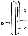
図1A〜1L
第1の変形では、前面10に対してアンダーカットされたスロット係止部3を有する成形部材1が使用される。スロット係止部3は両側面11,12に互いに対称に設けられ、対のスロットが形成されている。このスロットはそれぞれ同じ高さ位置に設けられている。対をなして対称に配置されたスロット3は下側に、それぞれ窓敷居状の段部30を備え、上側に、側面11,12の平面の方への傾斜部31を備えている。成形部材1を2つの部分、すなわち合成樹脂製の後側の条片18と、例えばアルミニウム製の前側の条片19によって形成すると特に有利である。後側の条片には、スロット3を加工することができる。前側の条片はスロット係止部3を越えるまで後側の条片を覆っている。それによって、このスロット係止部はアンダーカットされた輪郭を有する。両条片18,19はかみ合わせて組み立てられている。例えば後側条片18に設けられた矢印マークによって、正しい組み立て方向を示すことができる。成形部材1の1つの実施形では、後側の条片18を通って後側からボルト止めが行われる(図1F〜1H参照)。成形部材1の他の実施形では、前側の条片19を通って前側からボルト止めが行われる。この場合、ボルトのための穴とボルト頭を覆うために、被覆条片19′が設けられている。(図1I〜1K参照)。荷重支持体4を取付けたブラケット2は、上側のクランプ部分22とその下で下方に延びる支持部分23を有する取り囲み部材20を備えている。
1A-1L
In the first modification, the molded
図2A〜5C
ブラケット2は垂直方向に延びかつ成形部材1の横断面に対して相補的であるU字状の切欠きを備えている。それによって、ブラケット2を掛止めした状態で、この切欠き内に、成形部材1の前面10と両側面11,12を収容することができる。上側に位置するブラケット2のクランプ部分22には、切欠きの両側でばね5に支持され、側方へ制限されて移動可能なくさび50が挿入されている。このくさびは選択された対のスロット3に弾性的に係合するために設けられている。ばね5はくさび50を互いに向き合うように付勢する。くさびの尖端は停止位置で切欠き内に挿入されている。くさび50とばね5は、クランプ部分22の凹部に挿入されて互いに保持される別個の部品である。
2A-5C
The
ブラケット2が選択された高さ位置で正しくかつ荷重を支持するように成形部材1に掛けられると(この状態は係止位置と定義される)、ばね5によって押されたくさび50は対のスロット3内に挿入され、両スロット3の段部30に載る。掛止めされたブラケット2から成形部材1に作用する垂直な荷重成分は、対のスロット3に係合するくさび50によって受け止められる。下方に向いた斜めの荷重成分は、支持部分23とくさび50の側部によって受け止められる。くさび50は相互の方に充分に移動し、ブラケット2の下降運動が阻止される(図2C,3A,3B参照)。
When the
滑り位置の場合(図4A,4B参照)、ブラケット2は係止位置への挿入前の状態にあるかあるいはこの係止位置から外に移動するときの状態にある。成形部材1に懸架されるブラケット2が上方に持上げられると、くさび50は対のスロット3の傾斜部31に沿って上方に移動し始め、この場合ばね5の付勢力に抗して外側に押圧され、上方に移動して対のスロットから逸脱するにつれて徐々に開放する。
In the case of the sliding position (see FIGS. 4A and 4B), the
成形部材1に懸架されたブラケット2が更に上方に移動し、それに伴いブラケットが元の対のスロット3から益々逸脱すると、最後にブラケット2の自由位置が達成される(図2D,5A〜5C参照)。くさび50は対のスロット3から外に完全に移動し、その間の最大開放位置に達し、成形部材1の側面11,12に接触する。この状態で、ブラケット2を成形部材1から取り外し、元の対のスロット3に新たに係止させるために、更に上方にまたは再び下方に移動させることができる。
As the
分離位置では、ブラケット2は成形部材1から取り外されている。くさび50はばね5によって最大で切欠きの画成部まで切欠き内に押し込まれ、その際最小の相互間隔を有する(図2A参照)。くさび50の傾斜面によって、ブラケット2はあらゆる高さ位置で成形部材1に掛止めすることが可能である。
In the separation position, the
図6A〜7I
スロット係止部3を有する後側の条片18と前側の条片19とからなる成形部材1はきわめて有利である。図6A〜6Cにおいて成形部材1に掛けられたブラケット2は、図7A,7D〜7Iに示すように、いろいろな形状の荷重支持体4と組合せ可能である。
6A-7I
The molded
特別な形状と用途のために、成形部材1の短い片を支持構造体に固定することができる。このような短い片は少なくとも一対の両側のスロット3を備えている。このような成形片1にもブラケット2を掛止めすることができる。この場合、垂直方向の高さ移動は廃止される(図7B,7C参照)。
For special shapes and applications, a short piece of the molded
Claims (6)
b)成形部材(1)に掛止め可能なブラケット(2)が、係合輪郭部(3)と係合する固定要素(50)を備えており、その際
c)ブラケット(2)が、掛止状態で成形部材(1)の前面(10)と両側面(11,12)を取り囲む取り囲み部材(20)を備え、この取り囲み部材に固定要素(50)が設けられており、
d)ブラケット(2)が、成形部材(1)の前面(10)と両側面(11,12)とを取り囲んでいる、
懸架装置において、
e)固定要素(50)は、一つの貫通孔を有し、その貫通孔にばね(5)が挿入されて、ブラケット(2)の取り囲み部材(20)のクランプ部分(22)にばね(5)で支承される要素(50)であり、
f)成形部材(1)の係合輪郭部(3)が、成形部材(1)の側面(11,12)に設けられて、前面(10)の後側の切り込みとして構成されており、
g)固定要素(50)は、その貫通孔にばね(5)が挿入された状態で、ばね(5)の挿入方向と垂直な方向に対して貫通孔に沿ってスライドすることが可能である、
ことを特徴とする懸架装置。a) The vertically arranged molding member (1) comprises a front surface (10), two side surfaces (11, 12) and a back surface (13), the engagement contour (3) being the molding member (1). It is provided in
b) retaining capable bracket forming member (1) (2), engagement contour (3) and provided with a fixing element which engages (50), where c) the bracket (2) is multiplied An enclosing member (20) surrounding the front surface (10) and both side surfaces (11, 12) of the molded member (1) in a stationary state, and a fixing element (50) provided on the enclosing member;
d) A bracket (2) surrounds the front surface (10) and both side surfaces (11, 12) of the molded member (1).
In the suspension system,
e) The fixing element (50) has one through hole, into which the spring (5) is inserted, and the spring (5) is inserted into the clamp part (22) of the surrounding member (20) of the bracket (2). ) Is an element (50) supported by
f) The engagement contour (3) of the molded member (1) is provided on the side surfaces (11, 12) of the molded member (1) and is configured as a notch on the rear side of the front surface (10),
g) The fixing element (50) can slide along the through hole with respect to the direction perpendicular to the insertion direction of the spring (5) in a state where the spring (5) is inserted into the through hole. ,
A suspension device characterized by that.
b)ブラケット(2)の固定要素(50)が、それぞればね(5)に支持されたくさび(50)であり、それぞれ1個のばね(5)と1個のくさび(50)が、成形部材(1)を収容する切欠きの両側に設けられており、
c)ばね(5)とくさび(50)が、凹部内に挿入されて相互に保持している、
ことを特徴とする請求項1または2に記載の懸架装置。a) the engagement contour (3) on one side (11) is arranged symmetrically with respect to the engagement contour (3) on the other side (12);
b) The fixing elements (50) of the bracket (2) are wedges (50) each supported by a spring (5), one spring (5) and one wedge (50) each being a molded member (1) is provided on both sides of the notch for accommodating,
c) The spring (5) and the wedge (50) are inserted into the recess and held together,
The suspension apparatus according to claim 1 or 2, characterized in that
Applications Claiming Priority (2)
| Application Number | Priority Date | Filing Date | Title |
|---|---|---|---|
| CH21052001 | 2001-11-15 | ||
| PCT/CH2002/000612 WO2003041540A1 (en) | 2001-11-15 | 2002-11-14 | Suspension device comprising a profile rail that is to be vertically arranged, and comprising a bracket that can be suspended therein |
Publications (3)
| Publication Number | Publication Date |
|---|---|
| JP2005508685A JP2005508685A (en) | 2005-04-07 |
| JP2005508685A5 JP2005508685A5 (en) | 2006-01-05 |
| JP4421296B2 true JP4421296B2 (en) | 2010-02-24 |
Family
ID=4567529
Family Applications (1)
| Application Number | Title | Priority Date | Filing Date |
|---|---|---|---|
| JP2003543438A Expired - Lifetime JP4421296B2 (en) | 2001-11-15 | 2002-11-14 | Suspension device with molded rails to be placed vertically and brackets that can be hooked to them |
Country Status (15)
| Country | Link |
|---|---|
| US (1) | US7571882B2 (en) |
| EP (1) | EP1312287B1 (en) |
| JP (1) | JP4421296B2 (en) |
| CN (1) | CN100393261C (en) |
| AT (1) | ATE318092T1 (en) |
| BR (1) | BRPI0214223A2 (en) |
| CA (1) | CA2466512C (en) |
| CY (1) | CY1105558T1 (en) |
| DE (2) | DE50205870D1 (en) |
| DK (1) | DK1312287T5 (en) |
| ES (1) | ES2257526T3 (en) |
| HK (1) | HK1056106A1 (en) |
| PT (1) | PT1312287E (en) |
| RU (1) | RU2287311C2 (en) |
| WO (1) | WO2003041540A1 (en) |
Families Citing this family (46)
| Publication number | Priority date | Publication date | Assignee | Title |
|---|---|---|---|---|
| SE0200513L (en) * | 2002-02-21 | 2003-07-15 | Hl Display Ab | Device for product exposure spear |
| JP3742407B2 (en) * | 2003-06-27 | 2006-02-01 | 株式会社玉俊工業所 | Base structure of the shelf board |
| JP3919705B2 (en) | 2003-06-27 | 2007-05-30 | 株式会社玉俊工業所 | Base structure of the shelf board |
| US8225946B2 (en) | 2006-06-29 | 2012-07-24 | Simplehuman, Llc | Shelving system |
| DE102007022679B4 (en) * | 2007-05-11 | 2009-04-23 | Wanzl Metallwarenfabrik Gmbh | Market stalls |
| JP2009072393A (en) * | 2007-09-21 | 2009-04-09 | Sanuki:Kk | Shelf board support device |
| EP2229080B1 (en) * | 2007-12-11 | 2014-07-02 | Visplay International AG | Suspension device comprising a profiled vertical prop and a primary support that can be hooked thereto |
| US20090188880A1 (en) * | 2008-01-28 | 2009-07-30 | Simplehuman, Llc | Shelving system |
| DK200800111A (en) * | 2008-01-29 | 2009-07-30 | Containersign V Anders Waesel | A sign for affixing to a post of a container |
| US7938373B2 (en) * | 2008-02-13 | 2011-05-10 | Evapco, Inc. | Vertical support structure |
| US7963492B2 (en) * | 2008-02-19 | 2011-06-21 | Evapco, Inc. | Vertical support structure |
| US20100127141A1 (en) * | 2008-07-17 | 2010-05-27 | Herman Chan | Slotted Toolless Bracket for PDU |
| US20110215212A1 (en) * | 2008-11-14 | 2011-09-08 | Aydin Keyvanloo | Vertical mounting system |
| US8474632B2 (en) | 2008-12-01 | 2013-07-02 | Simplehuman, Llc | Shelving system |
| USD622990S1 (en) | 2009-03-20 | 2010-09-07 | Simplehuman, Llc | Shelving system |
| JP5215252B2 (en) * | 2009-06-29 | 2013-06-19 | ダイワラクダ工業株式会社 | Pipe socket |
| US8251324B2 (en) * | 2009-09-23 | 2012-08-28 | Liberty Hardware Mfg. Corp. | Support arm positioning tab |
| USD628841S1 (en) | 2009-12-01 | 2010-12-14 | Simplehuman, Llc | Shelving system |
| US8424241B2 (en) * | 2009-12-24 | 2013-04-23 | George M. Schaeffer | Trellising cross arm |
| USD651838S1 (en) | 2010-03-12 | 2012-01-10 | Simplehuman, Llc | Shelving system |
| USD651837S1 (en) | 2010-03-12 | 2012-01-10 | Simplehuman, Llc | Shelving system |
| US9307848B2 (en) | 2012-08-28 | 2016-04-12 | David Bernstein | Product display system |
| US8814108B2 (en) | 2012-08-28 | 2014-08-26 | David Bernstein | Product display system |
| DE202012008735U1 (en) | 2012-09-12 | 2012-10-18 | Visplay International Ag | Hanging device for presenting goods with a mountable on a support structure holder can be suspended therein primary carrier |
| CN104729218A (en) * | 2013-12-23 | 2015-06-24 | 海尔集团公司 | Adjustable shelf and refrigeration equipment |
| DE102014202699A1 (en) | 2014-02-14 | 2015-08-20 | Visplay International Ag | Suspension device for the presentation of goods |
| USD727060S1 (en) | 2014-03-12 | 2015-04-21 | Simplehuman, Llc | Shelving system |
| USD726441S1 (en) | 2014-03-12 | 2015-04-14 | Simplehuman, Llc | Shelving system |
| USD734956S1 (en) | 2014-03-13 | 2015-07-28 | Simplehuman, Llc | Shelving system |
| US9943192B2 (en) | 2014-03-13 | 2018-04-17 | Simplehuman, Llc | Shelving system with obscurable shelving |
| US9339151B2 (en) | 2014-03-13 | 2016-05-17 | Simplehuman, Llc | Shelving system with obscurable shelving |
| US9883742B2 (en) | 2014-03-14 | 2018-02-06 | Simplehuman, Llc | Shower caddy with shelf adjustably maounted along an elongate support member |
| US9487960B2 (en) | 2014-06-17 | 2016-11-08 | One Energy Enterprises Llc | Suspended deck systems, kits, and methods of installing, inspecting, and repairing a suspended deck system |
| CN104473437B (en) * | 2014-12-15 | 2016-05-18 | 尹宏 | A kind of Suspended table with top of variable height panel assembly |
| USD770197S1 (en) | 2015-02-23 | 2016-11-01 | Simplehuman, Llc | Shower caddy |
| USD769641S1 (en) | 2015-02-23 | 2016-10-25 | Simplehuman, Llc | Shower caddy |
| USD770198S1 (en) | 2015-02-25 | 2016-11-01 | Simplehuman, Llc | Shelving system |
| USD766688S1 (en) * | 2015-03-04 | 2016-09-20 | Lifetime Brands, Inc. | Corkscrew |
| CN104816869B (en) * | 2015-04-23 | 2017-01-25 | 中车眉山车辆有限公司 | Double-contact tray bearing seat |
| USD800396S1 (en) * | 2015-10-23 | 2017-10-17 | Andrew G. Coviello | Adjustable height pet feeder |
| CN105470756B (en) * | 2015-11-13 | 2019-01-11 | 厦门上特展示系统工程有限公司 | Hang electrified system |
| USD824189S1 (en) | 2017-02-23 | 2018-07-31 | Simplehuman, Llc | Shower caddy |
| EP3403526B1 (en) * | 2017-05-15 | 2019-10-09 | Peka-Metall AG | Shelf |
| US10921050B1 (en) | 2019-10-10 | 2021-02-16 | Whirlpool Corporation | Support assembly for appliance |
| US20210169278A1 (en) * | 2019-12-09 | 2021-06-10 | Mitchell April M | Organizer system and method of use |
| CN113775901B (en) * | 2020-06-10 | 2022-11-04 | 启碁科技股份有限公司 | Suspension type fixing seat and bracket unit thereof |
Family Cites Families (24)
| Publication number | Priority date | Publication date | Assignee | Title |
|---|---|---|---|---|
| US2026223A (en) * | 1933-06-27 | 1935-12-31 | Frank A Donnelly | Shelving |
| US2229473A (en) * | 1939-03-04 | 1941-01-21 | Norman W Redmer | Tripod |
| FR945260A (en) | 1945-03-03 | 1949-04-29 | Church & Company Fittings Ltd | Cleat for supporting wall shelves, shelves or the like |
| US2872144A (en) * | 1952-10-28 | 1959-02-03 | Nancy Hobson | Adjustable bracket supports for display and other purposes |
| USRE27200E (en) * | 1968-04-24 | 1971-10-26 | Steel shelving | |
| US3512654A (en) * | 1968-05-09 | 1970-05-19 | Jarke Corp | Modular cantilever adjustable arm rack and joint assembly |
| US3794183A (en) * | 1971-07-06 | 1974-02-26 | Rack Eng Co | Adjustable storage rack |
| US3854686A (en) * | 1972-06-21 | 1974-12-17 | Speedrack Inc | Cantilever rack |
| US4205629A (en) * | 1978-04-24 | 1980-06-03 | Wix Thomas R | Adjustable height bowl holding apparatus |
| US4348989A (en) * | 1980-02-25 | 1982-09-14 | Vik Darrell D | Adjustable waterer |
| US4444323A (en) * | 1981-05-11 | 1984-04-24 | Travis Handling Systems, Inc. | Retaining means for adjustable cantilever storage racks |
| US4553726A (en) * | 1983-09-19 | 1985-11-19 | Ex-Cell-O Corporation | Adjustable height seat apparatus for combat vehicle |
| DE3334709C2 (en) * | 1983-09-24 | 1985-07-25 | Jean Walterscheid Gmbh, 5204 Lohmar | Telescopic shaft |
| GB2154429A (en) | 1984-02-27 | 1985-09-11 | Pioneer Seed Company | Shelving system |
| CN2113664U (en) * | 1992-01-28 | 1992-08-26 | 陈博文 | Frame combination rack |
| ATE163515T1 (en) | 1994-12-13 | 1998-03-15 | Fehlbaum & Co | SUPPORT ROD ARRANGEMENT FOR HANGING GOODS TO BE DISPLAYED OR FOR HOLDING A GOODS SHELF |
| EP0941680A1 (en) | 1998-03-13 | 1999-09-15 | Fehlbaum & Co. | Article hanger hook system for commercial and institutional services |
| EP0965296A1 (en) | 1998-06-18 | 1999-12-22 | Fehlbaum & Co. | Article display device |
| DE60041876D1 (en) | 1999-07-23 | 2009-05-07 | Philadelphia Children Hospital | Polyurethane derivative compositions and process for their preparation |
| FR2796820B1 (en) | 1999-07-28 | 2001-10-19 | Grosfillex Sarl | CONSOLE SHELF SUPPORT DEVICE |
| DE29922163U1 (en) | 1999-12-17 | 2000-02-17 | Fehlbaum & Co., Muttenz | Arrangement for hanging articles or for holding a shelf |
| DE20009028U1 (en) | 2000-05-19 | 2000-08-03 | Vitrashop Patente Ag, Muttenz | Support rod arrangement |
| DE20100181U1 (en) | 2001-01-06 | 2001-06-13 | Visplay Ip Ag, Muttenz | Profile for vertical arrangement and for hanging consoles |
| DE20109028U1 (en) | 2001-05-30 | 2001-08-23 | Wiedner, Klaus, 90768 Fürth | glasses |
-
2002
- 2002-11-14 DE DE50205870T patent/DE50205870D1/en not_active Expired - Lifetime
- 2002-11-14 WO PCT/CH2002/000612 patent/WO2003041540A1/en active Application Filing
- 2002-11-14 AT AT02405981T patent/ATE318092T1/en active
- 2002-11-14 RU RU2004117881/12A patent/RU2287311C2/en not_active IP Right Cessation
- 2002-11-14 JP JP2003543438A patent/JP4421296B2/en not_active Expired - Lifetime
- 2002-11-14 CN CNB028252438A patent/CN100393261C/en not_active Expired - Fee Related
- 2002-11-14 EP EP02405981A patent/EP1312287B1/en not_active Expired - Lifetime
- 2002-11-14 US US10/495,296 patent/US7571882B2/en not_active Expired - Lifetime
- 2002-11-14 CA CA002466512A patent/CA2466512C/en not_active Expired - Fee Related
- 2002-11-14 DK DK02405981T patent/DK1312287T5/en active
- 2002-11-14 BR BRPI0214223A patent/BRPI0214223A2/en not_active IP Right Cessation
- 2002-11-14 ES ES02405981T patent/ES2257526T3/en not_active Expired - Lifetime
- 2002-11-14 PT PT02405981T patent/PT1312287E/en unknown
- 2002-11-15 DE DE20217715U patent/DE20217715U1/en not_active Expired - Lifetime
-
2003
- 2003-11-20 HK HK03108452A patent/HK1056106A1/en not_active IP Right Cessation
-
2006
- 2006-05-04 CY CY20061100576T patent/CY1105558T1/en unknown
Also Published As
| Publication number | Publication date |
|---|---|
| ES2257526T3 (en) | 2006-08-01 |
| CN100393261C (en) | 2008-06-11 |
| DK1312287T3 (en) | 2006-06-26 |
| BRPI0214223A2 (en) | 2016-06-28 |
| RU2004117881A (en) | 2005-10-27 |
| DE20217715U1 (en) | 2003-02-20 |
| ATE318092T1 (en) | 2006-03-15 |
| DK1312287T5 (en) | 2006-07-17 |
| EP1312287B1 (en) | 2006-02-22 |
| CA2466512C (en) | 2008-07-29 |
| CY1105558T1 (en) | 2010-07-28 |
| CN1604748A (en) | 2005-04-06 |
| US20050040301A1 (en) | 2005-02-24 |
| HK1056106A1 (en) | 2004-02-06 |
| EP1312287A1 (en) | 2003-05-21 |
| CA2466512A1 (en) | 2003-05-22 |
| DE50205870D1 (en) | 2006-04-27 |
| US7571882B2 (en) | 2009-08-11 |
| PT1312287E (en) | 2006-06-30 |
| WO2003041540A1 (en) | 2003-05-22 |
| JP2005508685A (en) | 2005-04-07 |
| RU2287311C2 (en) | 2006-11-20 |
Similar Documents
| Publication | Publication Date | Title |
|---|---|---|
| JP4421296B2 (en) | Suspension device with molded rails to be placed vertically and brackets that can be hooked to them | |
| JP2005508685A5 (en) | ||
| EP0055549A2 (en) | Display of merchandise | |
| US20090014400A1 (en) | Hook/hanger component mounting systems, components thereof, and related methods | |
| US4889304A (en) | All plastic display hook with locking feature | |
| JP4370093B2 (en) | Shelf bracket device | |
| JP2000507800A (en) | Switchboard with assembly board | |
| EP1585407B1 (en) | A system for detachable suspension of shelves, drawers or the like | |
| JPH03114411A (en) | Article-showing system | |
| JP3614083B2 (en) | Electronic shelf label mounting device | |
| EP2886012B1 (en) | Fastening system for furnitures | |
| US4903444A (en) | Floor grating | |
| JP2848780B2 (en) | Article attachment | |
| US5439280A (en) | File hanger system and clips therefor | |
| NL7907074A (en) | FASTENING DEVICE FOR WALL CLADDING PLATES. | |
| JPH0755948Y2 (en) | Bracket retaining device | |
| GB2322795A (en) | Shelf mounting with recess or channel | |
| JP2004057325A (en) | Commodity display apparatus | |
| JPS6244669Y2 (en) | ||
| JP3196544B2 (en) | Locking device for connecting rod | |
| JPH0583289U (en) | Blind headrail cover | |
| JP4624609B2 (en) | Scaffolding board | |
| JPH0119902Y2 (en) | ||
| JP3052119B2 (en) | Divider device in bookcase etc. | |
| JP2001314290A (en) | Cover device for support of rack system |
Legal Events
| Date | Code | Title | Description |
|---|---|---|---|
| A521 | Request for written amendment filed |
Free format text: JAPANESE INTERMEDIATE CODE: A523 Effective date: 20050704 |
|
| A621 | Written request for application examination |
Free format text: JAPANESE INTERMEDIATE CODE: A621 Effective date: 20050704 |
|
| A131 | Notification of reasons for refusal |
Free format text: JAPANESE INTERMEDIATE CODE: A131 Effective date: 20080401 |
|
| A601 | Written request for extension of time |
Free format text: JAPANESE INTERMEDIATE CODE: A601 Effective date: 20080630 |
|
| A602 | Written permission of extension of time |
Free format text: JAPANESE INTERMEDIATE CODE: A602 Effective date: 20080707 |
|
| A521 | Request for written amendment filed |
Free format text: JAPANESE INTERMEDIATE CODE: A523 Effective date: 20081001 |
|
| A02 | Decision of refusal |
Free format text: JAPANESE INTERMEDIATE CODE: A02 Effective date: 20081202 |
|
| A521 | Request for written amendment filed |
Free format text: JAPANESE INTERMEDIATE CODE: A821 Effective date: 20090302 |
|
| A521 | Request for written amendment filed |
Free format text: JAPANESE INTERMEDIATE CODE: A523 Effective date: 20090401 |
|
| A911 | Transfer to examiner for re-examination before appeal (zenchi) |
Free format text: JAPANESE INTERMEDIATE CODE: A911 Effective date: 20090608 |
|
| A131 | Notification of reasons for refusal |
Free format text: JAPANESE INTERMEDIATE CODE: A131 Effective date: 20090818 |
|
| A521 | Request for written amendment filed |
Free format text: JAPANESE INTERMEDIATE CODE: A523 Effective date: 20091007 |
|
| TRDD | Decision of grant or rejection written | ||
| A01 | Written decision to grant a patent or to grant a registration (utility model) |
Free format text: JAPANESE INTERMEDIATE CODE: A01 Effective date: 20091124 |
|
| A01 | Written decision to grant a patent or to grant a registration (utility model) |
Free format text: JAPANESE INTERMEDIATE CODE: A01 |
|
| A61 | First payment of annual fees (during grant procedure) |
Free format text: JAPANESE INTERMEDIATE CODE: A61 Effective date: 20091202 |
|
| FPAY | Renewal fee payment (event date is renewal date of database) |
Free format text: PAYMENT UNTIL: 20121211 Year of fee payment: 3 |
|
| R150 | Certificate of patent or registration of utility model |
Ref document number: 4421296 Country of ref document: JP Free format text: JAPANESE INTERMEDIATE CODE: R150 Free format text: JAPANESE INTERMEDIATE CODE: R150 |
|
| FPAY | Renewal fee payment (event date is renewal date of database) |
Free format text: PAYMENT UNTIL: 20131211 Year of fee payment: 4 |
|
| R250 | Receipt of annual fees |
Free format text: JAPANESE INTERMEDIATE CODE: R250 |
|
| R250 | Receipt of annual fees |
Free format text: JAPANESE INTERMEDIATE CODE: R250 |
|
| R250 | Receipt of annual fees |
Free format text: JAPANESE INTERMEDIATE CODE: R250 |
|
| R250 | Receipt of annual fees |
Free format text: JAPANESE INTERMEDIATE CODE: R250 |
|
| R250 | Receipt of annual fees |
Free format text: JAPANESE INTERMEDIATE CODE: R250 |
|
| R250 | Receipt of annual fees |
Free format text: JAPANESE INTERMEDIATE CODE: R250 |
|
| R250 | Receipt of annual fees |
Free format text: JAPANESE INTERMEDIATE CODE: R250 |
|
| R250 | Receipt of annual fees |
Free format text: JAPANESE INTERMEDIATE CODE: R250 |
|
| R250 | Receipt of annual fees |
Free format text: JAPANESE INTERMEDIATE CODE: R250 |
|
| R250 | Receipt of annual fees |
Free format text: JAPANESE INTERMEDIATE CODE: R250 |
|
| S111 | Request for change of ownership or part of ownership |
Free format text: JAPANESE INTERMEDIATE CODE: R313113 |
|
| R350 | Written notification of registration of transfer |
Free format text: JAPANESE INTERMEDIATE CODE: R350 |
|
| EXPY | Cancellation because of completion of term |