RU2267582C2 - Toilet system including lavatory pan - Google Patents
Toilet system including lavatory pan Download PDFInfo
- Publication number
- RU2267582C2 RU2267582C2 RU2003122781/03A RU2003122781A RU2267582C2 RU 2267582 C2 RU2267582 C2 RU 2267582C2 RU 2003122781/03 A RU2003122781/03 A RU 2003122781/03A RU 2003122781 A RU2003122781 A RU 2003122781A RU 2267582 C2 RU2267582 C2 RU 2267582C2
- Authority
- RU
- Russia
- Prior art keywords
- pressure chamber
- toilet
- pressure
- piston
- mass
- Prior art date
Links
- 238000011010 flushing procedure Methods 0.000 claims abstract description 20
- XLYOFNOQVPJJNP-UHFFFAOYSA-N water Substances O XLYOFNOQVPJJNP-UHFFFAOYSA-N 0.000 claims abstract description 15
- 230000007246 mechanism Effects 0.000 claims description 5
- 239000010865 sewage Substances 0.000 abstract description 4
- 230000000694 effects Effects 0.000 abstract description 2
- 239000000126 substance Substances 0.000 abstract description 2
- 238000000034 method Methods 0.000 description 7
- 230000008569 process Effects 0.000 description 6
- 238000005406 washing Methods 0.000 description 5
- 239000012528 membrane Substances 0.000 description 4
- 238000007789 sealing Methods 0.000 description 3
- 239000002699 waste material Substances 0.000 description 3
- 238000009434 installation Methods 0.000 description 2
- 230000035515 penetration Effects 0.000 description 2
- 238000005086 pumping Methods 0.000 description 2
- 230000001105 regulatory effect Effects 0.000 description 2
- 238000005507 spraying Methods 0.000 description 2
- 230000009471 action Effects 0.000 description 1
- 230000008901 benefit Effects 0.000 description 1
- 230000015572 biosynthetic process Effects 0.000 description 1
- 230000002349 favourable effect Effects 0.000 description 1
- 238000001556 precipitation Methods 0.000 description 1
- 239000000565 sealant Substances 0.000 description 1
- 239000007787 solid Substances 0.000 description 1
- 238000009736 wetting Methods 0.000 description 1
Images


Classifications
-
- E—FIXED CONSTRUCTIONS
- E03—WATER SUPPLY; SEWERAGE
- E03F—SEWERS; CESSPOOLS
- E03F1/00—Methods, systems, or installations for draining-off sewage or storm water
- E03F1/006—Pneumatic sewage disposal systems; accessories specially adapted therefore
-
- E—FIXED CONSTRUCTIONS
- E03—WATER SUPPLY; SEWERAGE
- E03D—WATER-CLOSETS OR URINALS WITH FLUSHING DEVICES; FLUSHING VALVES THEREFOR
- E03D5/00—Special constructions of flushing devices, e.g. closed flushing system
Landscapes
- Engineering & Computer Science (AREA)
- Health & Medical Sciences (AREA)
- Life Sciences & Earth Sciences (AREA)
- Hydrology & Water Resources (AREA)
- Public Health (AREA)
- Water Supply & Treatment (AREA)
- Aviation & Aerospace Engineering (AREA)
- Sanitary Device For Flush Toilet (AREA)
Abstract
Description
Область техникиTechnical field
Настоящее изобретение относится к туалетной системе с унитазом согласно независимому п.1 формулы изобретения.The present invention relates to a toilet system with a toilet according to the independent claim 1 of the claims.
Уровень техникиState of the art
Из патента США 2865028 известна туалетная система с унитазом для передвижных домиков, в котором откачиваемая масса посредством поршневого цилиндра засасывается из унитаза и выталкивается в канал для устранения отходов. Известная система, которая может быть выбрана в качестве ближайшего аналога изобретения, содержит унитаз; промывное устройство для обеспечения воды для смыва; линию, подсоединенную к унитазу и ведущую в канализационный трубопровод; средства для транспортировки откачиваемой массы от унитаза в линию и в канализационный трубопровод. Указанные средства содержат в линии два клапана и напорную камеру, в которой для отвода откачиваемой массы из унитаза создается пониженное давление, а для направления отведенной откачиваемой массы в канализационный трубопровод создается избыточное давление. Напорная камера выполнена в виде поршневого цилиндра и снабжена поршнем, связанным с ручным рычагом для приведения поршня в движение с целью создания пониженного давления и избыточного давления. К выходу напорной камеры подсоединена напорная линия, посредством которой откачиваемая масса транспортируется в канализационный трубопровод.From US Pat. No. 2,865,028, a toilet system with a toilet for mobile homes is known in which the pumped mass is sucked from the toilet by a piston cylinder and pushed into a waste disposal channel. The known system, which can be selected as the closest analogue of the invention, contains a toilet; a flushing device for providing flushing water; a line connected to the toilet and leading to the sewer; means for transporting the pumped mass from the toilet to the line and to the sewer pipe. These means contain two valves in the line and a pressure chamber, in which a reduced pressure is created to divert the pumped mass from the toilet, and an excess pressure is created to direct the pumped mass to the sewer pipe. The pressure chamber is made in the form of a piston cylinder and is equipped with a piston connected with a hand lever for driving the piston in order to create a reduced pressure and overpressure. A pressure line is connected to the outlet of the pressure chamber, through which the pumped-out mass is transported to the sewer pipe.
Туалетные устройства, у которых отходы откачиваются посредством вакуума, до сих пор применяются прежде всего на транспортных средствах, к примеру, в железнодорожных вагонах и в жилых автофургонах. Например, из международной публикации WO 92/18713 известна туалетная установка, в которой устройство для создания низкого давления (разрежения) содержит промежуточный контейнер и контейнер для сбора. Вышеупомянутое устройство для создания разрежения вакуумирует промежуточный контейнер таким образом, что при открытом вентиле откачиваемая масса по каналу всасывается в промежуточный контейнер. Вышеуказанный контейнер для сбора требует большой площади и должен опустошаться. Его применение нежелательно в домашней технике.Toilet devices in which waste is pumped out by vacuum are still used primarily on vehicles, for example, in railway cars and in camper vans. For example, from the international publication WO 92/18713, a toilet installation is known in which the device for generating low pressure (vacuum) comprises an intermediate container and a collection container. The aforementioned device for creating a vacuum vacuumizes the intermediate container so that when the valve is open, the pumped mass is sucked through the channel into the intermediate container. The above collection container requires a large area and must be emptied. Its use is undesirable in home appliances.
Из патентного документа ЕР 0887478 известно туалетное устройство, у которого также предусмотрен резервуар. Посредством мембранного (диафрагменного) насоса в резервуаре создается частичный вакуум, при помощи которого осуществляется эффект отсасывания.From patent document EP 0887478, a toilet device is known, which also has a reservoir. By means of a membrane (diaphragm) pump, a partial vacuum is created in the tank, with the help of which a suction effect is realized.
Из патентного документа ЕР 0806527 известно промывное устройство, которое содержит полый чашеобразный запорный элемент. Запорный элемент работает совместно с входным и выходным отверстиями, которые соответственно либо оба открыты, либо оба закрыты.From the patent document EP 0806527, a washing device is known which comprises a hollow cup-shaped locking element. The locking element works in conjunction with the inlet and outlet openings, which respectively are either both open or both closed.
Помимо этого, туалетные системы со сборным резервуаром известны из патентных документов ЕР 0704372 и ЕР 1022399.In addition, toilet systems with a collection tank are known from patent documents EP 0 704 372 and EP 1022399.
Из европейской заявки ЕР 0763633 А1 известен отсасывающий туалет, который содержит напорную камеру в сливном канале между двумя клапанами. Благодаря разрежению в этой камере при открытии клапана со стороны входа откачиваемая масса от унитаза по сливному каналу всасывается в эту камеру. После переключения обоих клапанов при помощи давления откачиваемая масса направляется от камеры в следующий трубопровод. Для вакуумирования камеры предусмотрен эжекторный насос, который приводится в действие сжатым воздухом. Складки сильфона образуют гибкую мембрану, служат как уплотняющее средство и при этом должны предотвращать попадание загрязненного воздуха из сливного канала наружу. При создании разрежения натягивается пружина, а при ее расслаблении создается давление. У вышеописанного устройства недостаток состоит в том, что уплотнение данной камеры при помощи гибкой мембраны является дорогостоящим и ненадежным. Создание разряжения (вакуума) при помощи эжекторного насоса требует сравнительно большого времени. При этом достигаемое давление для отвода откачиваемой массы из камеры очень ограничено. Данное туалетное устройство вряд ли является пригодным в хозяйстве.From European application EP 0763633 A1, a suction toilet is known which contains a pressure chamber in a drain channel between two valves. Due to the vacuum in this chamber, when the valve is opened from the inlet side, the pumped-out mass from the toilet is sucked into this chamber through the drain channel. After switching both valves by means of pressure, the pumped-off mass is directed from the chamber to the next pipeline. An ejector pump is provided for evacuating the chamber, which is driven by compressed air. The folds of the bellows form a flexible membrane, serve as a sealing means and, at the same time, should prevent contaminated air from entering the drain channel. When creating a vacuum, a spring is stretched, and when it is relaxed, pressure is created. The above device has the disadvantage that sealing this chamber with a flexible membrane is expensive and unreliable. Creating a vacuum (vacuum) using an ejector pump requires a relatively long time. In this case, the achieved pressure for removing the pumped mass from the chamber is very limited. This toilet device is hardly suitable for the household.
Раскрытие изобретенияDisclosure of invention
Задачей настоящего изобретения является создание туалетной установки или системы вышеупомянутого типа, которая при незначительном расходе воды надежно функционирует и является долговечной.An object of the present invention is to provide a toilet installation or system of the aforementioned type, which, with little water consumption, functions reliably and is durable.
Эта задача решена в туалетной системе, содержащей унитаз; промывное устройство для обеспечения воды для смыва; линию, подсоединенную к унитазу и ведущую в канализационный трубопровод; средства для транспортировки откачиваемой массы от унитаза в линию и в канализационный трубопровод. Указанные средства содержат в линии два клапана и расположенную между ними напорную камеру, в которой для отвода откачиваемой массы из унитаза создается пониженное давление, а для направления отведенной откачиваемой массы в канализационный трубопровод создается избыточное давление. Напорная камера выполнена в виде поршневого цилиндра и снабжена поршнем, связанным с приводным механизмом и приводимым в движение указанным механизмом для создания пониженного давления и избыточного давления. Система также содержит электрическое управляющее устройство, выполненное с возможностью управления приводным механизмом и клапанами таким образом, что для отвода откачиваемой массы из унитаза поршень перемещается при нахождении клапанов в закрытом состоянии с созданием пониженного давления в напорной камере, после чего клапан быстро открывается для впуска откачиваемой массы из унитаза в напорную камеру.This problem is solved in a toilet system containing a toilet; a flushing device for providing flushing water; a line connected to the toilet and leading to the sewer; means for transporting the pumped mass from the toilet to the line and to the sewer pipe. These means contain two valves in the line and a pressure chamber located between them, in which a reduced pressure is created to divert the pumped mass from the toilet, and an excess pressure is created to direct the pumped mass to the sewer pipe. The pressure chamber is made in the form of a piston cylinder and is equipped with a piston connected to the drive mechanism and driven by the said mechanism to create reduced pressure and overpressure. The system also includes an electric control device, configured to control the actuator and valves in such a way that the piston moves when the valves are in the closed state with a reduced pressure in the pressure chamber to divert the pumped mass from the toilet, after which the valve quickly opens to let the pumped mass in from the toilet to the pressure chamber.
В системе согласно изобретению разрежение и избыточное давление (напор) создаются при помощи движения поршня. Это позволяет обеспечить очень быстрое создание разрежения, к примеру, в пределах долей секунды. Избыточное давление в напорной камере, соответственно, также может создаваться очень быстро и, помимо этого, может быть выше 1·105 Па, предпочтительно выше 1,5·105 Па, например, 2·105 Па. Следующее преимущество туалетной системы согласно настоящему изобретению заключается в том, что возможна точная регулировка хода поршня и, соответственно, объема откачиваемой массы. Также возможно проводить один за другим два или более циклов откачки. При этом возможно качественное осуществление промывки с очень небольшим количеством воды. Сам поршень внутри цилиндра может самостоятельно служить уплотняющим средством, что предотвращает выход загрязненного воздуха наружу. Таким образом, применение в качестве уплотнителя гибкой мембраны или подобного средства не является необходимым.In the system according to the invention, vacuum and overpressure (pressure) are created by the movement of the piston. This allows you to provide a very quick vacuum, for example, within fractions of a second. Overpressure in the pressure chamber, respectively, can also be created very quickly and, in addition, can be higher than 1 · 10 5 Pa, preferably above 1.5 · 10 5 Pa, for example, 2 · 10 5 Pa. A further advantage of the toilet system according to the present invention is that it is possible to fine-tune the stroke of the piston and, accordingly, the volume of pumped mass. It is also possible to carry out two or more pumping cycles one after the other. In this case, a high-quality flushing with a very small amount of water is possible. The piston inside the cylinder itself can serve as a sealing means, which prevents the release of contaminated air to the outside. Thus, the use of a flexible membrane or the like as a sealant is not necessary.
В предпочтительном варианте движение поршня осуществляется при помощи электромотора, то есть поршень приводится в действие электромеханически. В сочетании с управляющим устройством это позволяет осуществлять точное и четкое управление процессом отсасывания и, соответственно, процессом выпуска. Кроме того, эти процессы могут регулироваться и приспосабливаться к используемому унитазу.In a preferred embodiment, the piston is driven by an electric motor, that is, the piston is electromechanically actuated. In combination with a control device, this allows precise and precise control of the suction process and, accordingly, the exhaust process. In addition, these processes can be regulated and adapted to the toilet used.
В следующем предпочтительном варианте к выходу напорной камеры подсоединена напорная линия, посредством которой откачиваемая масса транспортируется в канализационный трубопровод.In a further preferred embodiment, a pressure line is connected to the outlet of the pressure chamber, by means of which the pumped mass is transported to the sewer pipe.
В особенно предпочтительном варианте между унитазом и поршневым цилиндром расположен всасывающий трубопровод, который входит в напорную камеру тангенциально и/или наклонно вниз. В этом случае напорная камера в своей нижней части содержит выход, к которому подсоединена напорная линия.In a particularly preferred embodiment, between the toilet and the piston cylinder there is a suction pipe that enters the pressure chamber tangentially and / or inclined downward. In this case, the pressure chamber in its lower part contains an outlet to which the pressure line is connected.
Напорная камера может быть также выполнена заодно с унитазом.The pressure chamber can also be made integral with the toilet.
Краткий перечень фигурShort list of figures
Ниже настоящее изобретение подробно поясняется соответствующими чертежами, которые изображают:Below the present invention is illustrated in detail by the relevant drawings, which depict:
Фиг.1 - схематичное изображение туалетной системы согласно изобретению;Figure 1 is a schematic illustration of a toilet system according to the invention;
Фиг.2 - следующее схематичное изображение настоящего изобретения;Figure 2 is the following schematic representation of the present invention;
Фиг.3 - схематичное изображение временного графика протекания процесса промывки;Figure 3 is a schematic representation of a time graph of the course of the washing process;
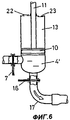
Фиг.4-6 - схематичное изображение процесса всасывания и выпуска откачиваемой массы.Figure 4-6 is a schematic illustration of a suction and discharge process of a pumped mass.
Сведения, подтверждающие возможность осуществления изобретенияInformation confirming the possibility of carrying out the invention
Туалетная система согласно Фиг.1 и Фиг.2 содержит унитаз 5, который выполнен воронкообразным и имеет нижний выход 5а. Этот выход выполнен со сравнительно малым поперечным сечением, например 30 мм2. К нижней стороне выхода 5а в линии 29 присоединен всасывающий трубопровод 6, который также выполнен с малым поперечным сечением. Унитаз 5 промывается при помощи промывного устройства 1 и смывной трубы 3, через которую вода для смыва попадает во внутреннюю часть унитаза 5. Промывное устройство 1 может быть выполнено в виде смывного бачка или другого подходящего промывного устройства. Существенным является то, что используемое количество воды является сравнительно малым, к примеру, меньшим чем один литр. Запуск процесса промывки осуществляется клавишей (кнопкой) 2 или другим предназначенным для этих целей пусковым устройством. Возможным в данном случае является также автоматический или бесконтактный запуск.The toilet system according to FIGS. 1 and 2 contains a
Во всасывающем трубопроводе 6 предусмотрен клапан 7, который в закрытом состоянии запирает всасывающий трубопровод 6, а в открытом состоянии открывает проход к напорной камере 12 поршневого цилиндра 8. Управление клапаном 7 осуществляется через сигнальный провод 24 от управляющего устройства 26.In the
Поршневой цилиндр 8 содержит корпус 9, в котором поршень 10 выполнен ограниченно подвижным в направлениях двойной стрелки 19. Поршень 10 разделяет корпус 9 на напорную камеру 12 и верхнюю камеру 13. Поршень 10 также уплотняет обе камеры 12 и 13 друг от друга. Для этого на внешней стороне поршня 10 расположено уплотнение. Поршень 10 приводится в движение приводом 14, например, выполненным в виде электродвигателя и соединенным с поршнем 10 посредством поршневого штока 11, который, как видно из чертежа, одним концом выступает из корпуса 9. При передвижении поршня 10 через клапаны 22 и 23 воздух из верхней камеры 13 выталкивается в окружающую среду и в камеру 13 запускается свежий воздух из окружающей среды соответственно. Клапаны 22 и 23 могут быть выполнены простыми створчатыми клапанами. Электроснабжение мотора 14 осуществляется по электропроводу 15. Через этот провод также питается устройство 26 управления. Устройство 26 управления может быть соединено с мотором 14.The
Напорная камера 12 содержит выход 12а, который расположен, как видно из чертежа, в самом низком месте напорной камеры 12 и к которому подсоединяется напорная линия 17. Напорная линия 17 может быть выполнена в виде гибкого шланга или обычного трубопровода. Вблизи от выхода 12а находится следующий клапан 16, который управляется управляющим устройством 26 через сигнальный провод 25. В одном положении клапана 16 проход к напорной линии 17 закрыт, а в другом его положении - открыт. Напорная камера 12 образует камеру нагнетания и она может быть интегрирована с унитазом 5 и образовывать с ним единое целое.The
Напорная линия 17 имеет поперечное сечение, которое может в основном соответствовать поперечному сечению всасывающего трубопровода 6. Это поперечное сечение, таким образом, также сравнительно мало и может сравниваться, например, с тем же садовым шлангом. Он может быть сравнительно длинен, к примеру несколько метров, и вести согласно Фиг.1 к стояку канализационного трубопровода 18, по которому в направлении стрелки 20 протекают канализационные стоки. Предпочтительно напорная линия 17 содержит передний конец 17а, который выдвигается сравнительно глубоко, к примеру на несколько метров, в канализационный трубопровод 18. Напорная линия 17 может быть введена в канализационный трубопровод 18, к примеру, посредством патрубка 18а.The
Ниже поясняется способ работы туалетной системы согласно изобретению.The following describes the method of operation of the toilet system according to the invention.
На Фиг.2 показана туалетная система в исходном положении. Клапаны 7 и 16 закрыты и поршень 10 находится в показанном нижнем положении. При использовании туалетной системы промывное устройство 1 может быть задействовано для предварительного смачивания или увлажнения внутренней части 5b унитаза 5. В результате увлажнения в унитазе 5 собирается откачиваемая масса 4, которая заполняет всасывающий трубопровод 6 до клапана 7. Промывка осуществляется путем нажатия клавиши (кнопки) пуска 2. При этом вода попадает в унитаз 5 через смывную трубу 3. Потребляемый в данном случае расход воды регулируется через устройство 26 управления и сигнальный провод 27. Предпочтительно система содержит одну или несколько насадок, через которые происходит разбрызгивание или распрыскивание воды по внутренней части 5b унитаза.Figure 2 shows the toilet system in its original position.
После опрыскивания поршень 10 передвигается примерно в положение, показанное на Фиг.4, при этом предпочтительно не достигать крайнего, т.е. самого высокого положения. Так как клапаны 7 и 16 еще находятся в закрытом состоянии, вследствие этого в напорной камере 12' создается пониженное давление, предпочтительно меньшее чем, например, 0,5·105 Па. Одновременно с помощью устройства 26 управления может осуществляться дальнейшая промывка унитаза 5. Почти одновременно с этим сравнительно быстро и, по существу, внезапно происходит открытие клапана 7. Быстрое открытие может осуществляться, например, посредством преднапряженной пружины (на чертеже не показана). Также практически одновременно с этим прерывается промывка унитаза 5. Напорная камера 12' имеет такие размеры, что она может быть наполнена примерно наполовину воздухом и примерно наполовину откачиваемой массой 4. При засасывании откачиваемой массы 4 вследствие внезапного впуска в напорную камеру 12' твердые вещества измельчаются, так что отведенная масса 4' представляет собой вещество, похожее на суспензию. На фиг.5 стрелкой 28 показано направление проникновения откачиваемой массы 4 в напорную камеру 12'. Над отведенной массой 4' находится воздушный буфер 21, который занимает, как упомянуто выше, примерно половину объема напорной камеры 12'.After spraying, the
Когда откачиваемая масса 4 отведена, клапан 7 закрывается и поршень 10 двигается вниз, при этом воздушный буфер 21 сжимается и создается избыточное давление, например, величиной 2·105 Па. Далее клапан 16 открывается и под действием созданного избыточного давления отведенная масса 4' направляется в напорную линию 17 и, окончательно, в канализационный трубопровод 18. Затем клапан 16 закрывается. При передвижении поршня 10 вниз свежий воздух из окружающей среды через клапан 22 поступает в верхнюю камеру 13. Как правило, напорная линия 17 по меньшей мере частично наполнена отведенной массой 4'. Для того, чтобы вытолкнуть также и эту массу, предпочтительно провести второй процесс промывки. При этом унитаз 5 еще раз омывается и эта вода для промывки всасывается в соответствии с уже вышеизложенным процессом и затем удаляется. Напорная линия 17 при помощи этого процесса промывается водой и, по меньшей мере, частично очищается. Эта отработанная промывочная вода поступает в канализационный трубопровод 18.When the pumped-out
Всасывающий трубопровод 6 входит в напорную камеру 12 предпочтительно тангенциально и предпочтительно с уклоном вниз. Это дает в итоге особенно благоприятную динамику откачиваемой массе 4 и тем самым проникновение и вытекание этой откачиваемой массы 4 в/из средств 8. Откачиваемая масса 4 устремляется тангенциально в направлении нижней части напорной камеры 12, при этом так сказать прополаскивает цилиндрический поршень 8 и вращается в напорной камере 12. Затем откачиваемая масса 4 выталкивается. Так как все это происходит в динамике, удается избежать образования осадков в напорной камере 12. При этом возможно все таки, что осажденные части будут снова намыты. Контакт с поршнем 10 и уплотнением в значительной степени устранен.The
Claims (9)
Applications Claiming Priority (2)
| Application Number | Priority Date | Filing Date | Title |
|---|---|---|---|
| CH143/01 | 2001-01-26 | ||
| CH1432001 | 2001-01-26 |
Publications (2)
| Publication Number | Publication Date |
|---|---|
| RU2003122781A RU2003122781A (en) | 2004-12-10 |
| RU2267582C2 true RU2267582C2 (en) | 2006-01-10 |
Family
ID=4399823
Family Applications (1)
| Application Number | Title | Priority Date | Filing Date |
|---|---|---|---|
| RU2003122781/03A RU2267582C2 (en) | 2001-01-26 | 2002-01-22 | Toilet system including lavatory pan |
Country Status (7)
| Country | Link |
|---|---|
| US (1) | US6910231B2 (en) |
| EP (1) | EP1354101B1 (en) |
| AT (1) | ATE390525T1 (en) |
| DE (1) | DE50211960D1 (en) |
| DK (1) | DK1354101T3 (en) |
| RU (1) | RU2267582C2 (en) |
| WO (1) | WO2002059432A1 (en) |
Cited By (2)
| Publication number | Priority date | Publication date | Assignee | Title |
|---|---|---|---|---|
| CN102191805A (en) * | 2011-03-23 | 2011-09-21 | 汤炳生 | Water closet living waste water automatic spray washing system |
| RU2458210C2 (en) * | 2007-04-04 | 2012-08-10 | Ликсил Корпорэйшн | Suction air device for toilet drain port |
Families Citing this family (14)
| Publication number | Priority date | Publication date | Assignee | Title |
|---|---|---|---|---|
| US20090100586A1 (en) * | 2007-10-23 | 2009-04-23 | Conley Gene E | Fresh water flushing device for marine sanitation devices |
| US8321967B2 (en) | 2008-08-01 | 2012-12-04 | Kohler Co. | Wall installed toilet |
| CN201512849U (en) * | 2009-09-24 | 2010-06-23 | 山东华腾环保科技有限公司 | Vacuum assisted toilet stool |
| DE102012102632B4 (en) | 2012-03-27 | 2015-05-28 | Aqua Vital Int. Ltd. & Co. KG | suction |
| US9416524B2 (en) * | 2013-03-05 | 2016-08-16 | David R. Hall | Piston-flush toilet system |
| DE202013008298U1 (en) * | 2013-09-20 | 2014-12-22 | Evac Gmbh | Vacuum toilet with alternating squeeze valve closing |
| DE202013011431U1 (en) * | 2013-12-20 | 2015-03-23 | Evac Gmbh | Vacuum toilet with centrifugal separator |
| US10280604B1 (en) * | 2015-11-09 | 2019-05-07 | Joseph D Maresh | Toilet having a water conservation peristaltic pump mode |
| EP3321439A1 (en) * | 2016-11-15 | 2018-05-16 | Alte Technologies S.L.U. | Waste transfer system for a toilet of a public transport vehicle |
| US20180142455A1 (en) * | 2016-11-22 | 2018-05-24 | David R. Hall | Piston Flush Toilet with a Lubricating Piston |
| US20210078507A1 (en) * | 2018-05-01 | 2021-03-18 | Thetford Bv | Wastewater management system for vehicles and related methods |
| WO2020190301A1 (en) | 2019-03-21 | 2020-09-24 | Brigham Young University | Vacuum-assisted toilet systems and methods of using the same |
| WO2020190300A1 (en) * | 2019-03-21 | 2020-09-24 | Brigham Young University | Vacuum-assisted toilet systems and methods of using the same |
| US11560704B2 (en) | 2019-03-21 | 2023-01-24 | Brigham Young University | Noise reduction pipes, vacuum-assisted toilet systems including the same, and methods of using the same |
Family Cites Families (13)
| Publication number | Priority date | Publication date | Assignee | Title |
|---|---|---|---|---|
| US1650370A (en) * | 1927-06-08 | 1927-11-22 | David J Mahoney | Marine toilet |
| US2865028A (en) * | 1955-10-04 | 1958-12-23 | Verne L Patenaude | Sewage system for mobile homes and the like |
| US4783859A (en) * | 1985-09-24 | 1988-11-15 | Monogram Industries, Inc. | Aircraft toilet flush valve |
| US5122352A (en) * | 1988-03-08 | 1992-06-16 | Johnson Arthur F | Heat exchanger and pollutant removal system |
| US5198201A (en) * | 1988-03-08 | 1993-03-30 | Johnson Arthur F | Removal of sulphur and nitrogen oxides from flue gases |
| US5230870A (en) * | 1992-05-26 | 1993-07-27 | Johnson Arthur F | Method for converting noxious pollutants from flue gas into merchantable by-products |
| DE4136931A1 (en) | 1991-04-23 | 1992-10-29 | Rauno Haatanen | DRAIN SYSTEM FOR THE DRAIN UNIT OF A UNIT PRODUCING UNIT |
| DE4434437C2 (en) | 1994-09-27 | 1996-10-02 | Daimler Benz Aerospace Airbus | Vacuum toilet system in an airplane |
| DK0763633T3 (en) | 1995-09-13 | 2000-03-20 | Evac Ab | Membrane controlled vacuum sewer system |
| FR2740354B1 (en) * | 1995-10-31 | 1997-11-28 | Rhone Poulenc Chimie | PROCESS FOR THE TREATMENT OF FUMES BASED ON SULFUR OXIDES |
| IT1295231B1 (en) | 1996-05-08 | 1999-05-04 | Vitaliano Gagliano | FORCED FLUSH SYSTEM PREFERRED FOR WC AND SIMILAR, WORKING WITH COMPRESSED AIR, ALSO SUITABLE FOR CONCEALED SWIVEL TOILETS |
| US6082979A (en) | 1997-06-23 | 2000-07-04 | Sealand Technology, Inc. | Air pump for vacuum toilet systems |
| FI105223B (en) | 1999-01-20 | 2000-06-30 | Evac Int Oy | Vacuum drainage system drain device |
-
2002
- 2002-01-22 AT AT02734839T patent/ATE390525T1/en active
- 2002-01-22 DK DK02734839T patent/DK1354101T3/en active
- 2002-01-22 DE DE50211960T patent/DE50211960D1/en not_active Expired - Lifetime
- 2002-01-22 EP EP02734839A patent/EP1354101B1/en not_active Expired - Lifetime
- 2002-01-22 US US10/470,190 patent/US6910231B2/en not_active Expired - Fee Related
- 2002-01-22 RU RU2003122781/03A patent/RU2267582C2/en not_active IP Right Cessation
- 2002-01-22 WO PCT/CH2002/000031 patent/WO2002059432A1/en active IP Right Grant
Cited By (2)
| Publication number | Priority date | Publication date | Assignee | Title |
|---|---|---|---|---|
| RU2458210C2 (en) * | 2007-04-04 | 2012-08-10 | Ликсил Корпорэйшн | Suction air device for toilet drain port |
| CN102191805A (en) * | 2011-03-23 | 2011-09-21 | 汤炳生 | Water closet living waste water automatic spray washing system |
Also Published As
| Publication number | Publication date |
|---|---|
| EP1354101B1 (en) | 2008-03-26 |
| ATE390525T1 (en) | 2008-04-15 |
| US6910231B2 (en) | 2005-06-28 |
| US20040064881A1 (en) | 2004-04-08 |
| WO2002059432A8 (en) | 2003-11-06 |
| WO2002059432A1 (en) | 2002-08-01 |
| DE50211960D1 (en) | 2008-05-08 |
| EP1354101A1 (en) | 2003-10-22 |
| DK1354101T3 (en) | 2008-07-14 |
Similar Documents
| Publication | Publication Date | Title |
|---|---|---|
| RU2267582C2 (en) | Toilet system including lavatory pan | |
| EP0530859B1 (en) | Vacuum toilet system | |
| JP2774199B2 (en) | Portable toilet facilities | |
| US6367095B2 (en) | Flushing device for a toilet | |
| JP2007218037A (en) | Toilet bowl flushing device and flushing method | |
| KR20070116070A (en) | Toilet flushing system using compressed air | |
| KR20080106174A (en) | Toilet bowl flushing device | |
| US4791688A (en) | Jet pump macerator pump sewage handling system | |
| KR100558434B1 (en) | Device for controlling the discharge valve and flushing | |
| JP4305359B2 (en) | Toilet device | |
| JP2823095B2 (en) | Suction pressure vessel | |
| JP2007046307A (en) | Toilet bowl flushing apparatus | |
| JPH0585698B2 (en) | ||
| KR20180110097A (en) | Toilet structure | |
| US6061844A (en) | Water-conserving toilet having independently flushable main and urinal bowls | |
| JP4305360B2 (en) | Toilet device | |
| CN216766114U (en) | Toilet seat | |
| KR20030071515A (en) | Arrangement for a urinal | |
| EP0515134B1 (en) | Improvements in and relating to vacuum sewage systems | |
| JP2002201690A (en) | Trap device with auxiliary seal water supply mechanism | |
| CA2177126A1 (en) | Flushing means with a toilet bowl | |
| JP4517976B2 (en) | Toilet bowl cleaning device | |
| KR20010013299A (en) | Toilet system with vacuum suction | |
| JP4345662B2 (en) | Western-style toilet equipment | |
| US6442771B1 (en) | Flushing device |
Legal Events
| Date | Code | Title | Description |
|---|---|---|---|
| MM4A | The patent is invalid due to non-payment of fees |
Effective date: 20080123 |