RU2266445C2 - Tension device for belt drive of auxiliary members - Google Patents
Tension device for belt drive of auxiliary members Download PDFInfo
- Publication number
- RU2266445C2 RU2266445C2 RU2003112681/11A RU2003112681A RU2266445C2 RU 2266445 C2 RU2266445 C2 RU 2266445C2 RU 2003112681/11 A RU2003112681/11 A RU 2003112681/11A RU 2003112681 A RU2003112681 A RU 2003112681A RU 2266445 C2 RU2266445 C2 RU 2266445C2
- Authority
- RU
- Russia
- Prior art keywords
- pulley
- belt
- tensioner
- drive
- tension
- Prior art date
Links
Images


Classifications
-
- F—MECHANICAL ENGINEERING; LIGHTING; HEATING; WEAPONS; BLASTING
- F16—ENGINEERING ELEMENTS AND UNITS; GENERAL MEASURES FOR PRODUCING AND MAINTAINING EFFECTIVE FUNCTIONING OF MACHINES OR INSTALLATIONS; THERMAL INSULATION IN GENERAL
- F16H—GEARING
- F16H7/00—Gearings for conveying rotary motion by endless flexible members
- F16H7/08—Means for varying tension of belts, ropes, or chains
- F16H7/10—Means for varying tension of belts, ropes, or chains by adjusting the axis of a pulley
- F16H7/12—Means for varying tension of belts, ropes, or chains by adjusting the axis of a pulley of an idle pulley
- F16H7/1209—Means for varying tension of belts, ropes, or chains by adjusting the axis of a pulley of an idle pulley with vibration damping means
- F16H7/1218—Means for varying tension of belts, ropes, or chains by adjusting the axis of a pulley of an idle pulley with vibration damping means of the dry friction type
-
- F—MECHANICAL ENGINEERING; LIGHTING; HEATING; WEAPONS; BLASTING
- F02—COMBUSTION ENGINES; HOT-GAS OR COMBUSTION-PRODUCT ENGINE PLANTS
- F02B—INTERNAL-COMBUSTION PISTON ENGINES; COMBUSTION ENGINES IN GENERAL
- F02B67/00—Engines characterised by the arrangement of auxiliary apparatus not being otherwise provided for, e.g. the apparatus having different functions; Driving auxiliary apparatus from engines, not otherwise provided for
- F02B67/04—Engines characterised by the arrangement of auxiliary apparatus not being otherwise provided for, e.g. the apparatus having different functions; Driving auxiliary apparatus from engines, not otherwise provided for of mechanically-driven auxiliary apparatus
- F02B67/06—Engines characterised by the arrangement of auxiliary apparatus not being otherwise provided for, e.g. the apparatus having different functions; Driving auxiliary apparatus from engines, not otherwise provided for of mechanically-driven auxiliary apparatus driven by means of chains, belts, or like endless members
-
- F—MECHANICAL ENGINEERING; LIGHTING; HEATING; WEAPONS; BLASTING
- F16—ENGINEERING ELEMENTS AND UNITS; GENERAL MEASURES FOR PRODUCING AND MAINTAINING EFFECTIVE FUNCTIONING OF MACHINES OR INSTALLATIONS; THERMAL INSULATION IN GENERAL
- F16H—GEARING
- F16H7/00—Gearings for conveying rotary motion by endless flexible members
- F16H7/08—Means for varying tension of belts, ropes, or chains
- F16H7/10—Means for varying tension of belts, ropes, or chains by adjusting the axis of a pulley
- F16H7/12—Means for varying tension of belts, ropes, or chains by adjusting the axis of a pulley of an idle pulley
- F16H7/1209—Means for varying tension of belts, ropes, or chains by adjusting the axis of a pulley of an idle pulley with vibration damping means
-
- F—MECHANICAL ENGINEERING; LIGHTING; HEATING; WEAPONS; BLASTING
- F16—ENGINEERING ELEMENTS AND UNITS; GENERAL MEASURES FOR PRODUCING AND MAINTAINING EFFECTIVE FUNCTIONING OF MACHINES OR INSTALLATIONS; THERMAL INSULATION IN GENERAL
- F16H—GEARING
- F16H7/00—Gearings for conveying rotary motion by endless flexible members
- F16H7/08—Means for varying tension of belts, ropes, or chains
- F16H2007/0802—Actuators for final output members
- F16H2007/081—Torsion springs
-
- F—MECHANICAL ENGINEERING; LIGHTING; HEATING; WEAPONS; BLASTING
- F16—ENGINEERING ELEMENTS AND UNITS; GENERAL MEASURES FOR PRODUCING AND MAINTAINING EFFECTIVE FUNCTIONING OF MACHINES OR INSTALLATIONS; THERMAL INSULATION IN GENERAL
- F16H—GEARING
- F16H7/00—Gearings for conveying rotary motion by endless flexible members
- F16H7/08—Means for varying tension of belts, ropes, or chains
- F16H7/0829—Means for varying tension of belts, ropes, or chains with vibration damping means
- F16H2007/084—Means for varying tension of belts, ropes, or chains with vibration damping means having vibration damping characteristics dependent on the moving direction of the tensioner
-
- F—MECHANICAL ENGINEERING; LIGHTING; HEATING; WEAPONS; BLASTING
- F16—ENGINEERING ELEMENTS AND UNITS; GENERAL MEASURES FOR PRODUCING AND MAINTAINING EFFECTIVE FUNCTIONING OF MACHINES OR INSTALLATIONS; THERMAL INSULATION IN GENERAL
- F16H—GEARING
- F16H7/00—Gearings for conveying rotary motion by endless flexible members
- F16H7/08—Means for varying tension of belts, ropes, or chains
- F16H2007/0863—Finally actuated members, e.g. constructional details thereof
- F16H2007/0874—Two or more finally actuated members
-
- F—MECHANICAL ENGINEERING; LIGHTING; HEATING; WEAPONS; BLASTING
- F16—ENGINEERING ELEMENTS AND UNITS; GENERAL MEASURES FOR PRODUCING AND MAINTAINING EFFECTIVE FUNCTIONING OF MACHINES OR INSTALLATIONS; THERMAL INSULATION IN GENERAL
- F16H—GEARING
- F16H7/00—Gearings for conveying rotary motion by endless flexible members
- F16H7/08—Means for varying tension of belts, ropes, or chains
- F16H7/0829—Means for varying tension of belts, ropes, or chains with vibration damping means
Abstract
Description
Изобретение относится в целом к системам ременного привода вспомогательных устройств двигателя внутреннего сгорания, каждая из которых имеет унитарное устройство, выполняющее как функцию запуска двигателя, так и функцию выработки электрической энергии, такое как электродвигатель-генератор, иногда называемый стартером-генератором (Gen-Star). Более точно, оно относится к подобным системам, применяемым для автомобилей. В частности, данное изобретение относится к натяжному устройству и конструкции систем ременного привода, каждая из которых имеет электродвигатель/генератор и каждая из которых имеет натяжное устройство.The invention relates generally to belt drive systems of auxiliary devices of an internal combustion engine, each of which has a unitary device that performs both the function of starting the engine and the function of generating electric energy, such as an electric motor-generator, sometimes called a starter-generator (Gen-Star) . More precisely, it relates to similar systems used for automobiles. In particular, this invention relates to a tensioner and design of belt drive systems, each of which has an electric motor / generator and each of which has a tensioner.
Описание известного уровня техникиDescription of the prior art
Предназначенные для передачи мощности системы ременного привода обычно используются в двигателях внутреннего сгорания для отбора мощности с коленчатого вала двигателя и передачи ее к одному или более различных вспомогательных механизмов или вспомогательных устройств двигателя. В случаях применения в автомобилях данные вспомогательные устройства включают в себя насосы рулевого привода с усилителем, водяные насосы, компрессоры систем кондиционирования воздуха, топливные насосы и генераторы переменного тока. Исторически сложилось так, что подобные двигатели имели основное место отбора мощности на коленчатом валу, выступающем от задней части двигателя, к которому присоединена цепь привода для приведения в движение колес с целью обеспечения движения автомобиля. Привод вспомогательных устройств осуществляется от шкива, присоединенного к передней части коленчатого вала. Каждое вспомогательное устройство оснащено шкивом. Все шкивы механически связаны друг с другом посредством одного или более приводных ремней, охватывающих их. Предусмотрен какой-либо способ натяжения каждого приводного ремня. Приводной ремень, шкивы и устройства, осуществляющие натяжение ремня, образуют систему ременного привода вспомогательных устройств (систему вспомогательного ременного привода).Belt drive systems designed for power transmission are typically used in internal combustion engines to take power from a crankshaft of an engine and transmit it to one or more different auxiliary mechanisms or auxiliary devices of the engine. For automotive applications, these assistive devices include power steering pumps, water pumps, air conditioning compressors, fuel pumps and alternators. Historically, such engines have had a primary power take-off on a crankshaft protruding from the rear of the engine, to which a drive chain is connected to drive the wheels to provide vehicle movement. Auxiliary devices are driven by a pulley attached to the front of the crankshaft. Each accessory is equipped with a pulley. All pulleys are mechanically connected to each other by one or more drive belts covering them. There is some way to tension each drive belt. The drive belt, pulleys and belt tensioning devices form a belt drive system of auxiliary devices (auxiliary belt drive system).
Ранее разработанные и применявшиеся системы включали в себя множество клиновых ремней. Обычно каждый ремень натягивали путем регулировки вручную и фиксации положения одного вспомогательного устройства или натяжного ролика для одного ремня. Такие системы называют ременными приводами с заблокированным центром, поскольку не предусмотрено никакого автоматического перемещения ни одного из шкивов с целью приспосабливания к изменяющемуся состоянию ремня или привода в целом. Если ремень растянется или удлинится иным образом, натяжение на ремне уменьшится. Далее, для обеспечения надлежащей работы системы ременного привода необходимо создать натяжение ремня, достаточно большое, чтобы обеспечить возможность приспосабливания к состоянию, характерному для наихудшего случая. Такое состояние, характерное для наихудшего случая, может быть результатом экстремальных значений температуры, экстремальных режимов работы двигателя или работы вспомогательных устройств.Previously developed and applied systems included many V-belts. Typically, each belt was tensioned by manually adjusting and securing the position of one auxiliary device or a tension roller for one belt. Such systems are called belt drives with a locked center, since there is no automatic movement of any of the pulleys in order to adapt to the changing state of the belt or the drive as a whole. If the belt stretches or otherwise lengthens, the tension on the belt will decrease. Further, to ensure proper operation of the belt drive system, it is necessary to create a belt tension large enough to allow adaptation to the worst-case state. This worst-case condition may result from extreme temperatures, extreme engine operating conditions, or auxiliary devices.
Существует потребность уменьшить объем моторных отделений автомобилей. Для того, чтобы данные отделения можно было уменьшить по объему, различные элементы двигателей, включая системы ременного привода вспомогательных устройств, были выполнены с меньшими размерами. Это было выполнено, по меньшей мере частично, за счет уменьшения количества используемых ремней. При удалении любого ремня и уменьшении количества слоев, проходящих от передней части двигателя, общее расстояние, на которое система ременного привода выступает от передней части двигателя, таким образом уменьшается. В конце концов это привело к использованию одного змеевидного ремня для многих применяемых устройств. Змеевидный ремень назван таким образом из-за того, как он обвивает различные шкивы, образуя последовательность изгибов как вперед, так и назад. Клиновой ремень или Micro-V (зарегистрированный товарный знак The Gates Rubber Company) ремень наиболее подходит для тех случаев применения, где ремень должен "извиваться" подобно змее.There is a need to reduce the volume of motor compartments of cars. In order for these compartments to be reduced in volume, various engine elements, including belt drive systems for auxiliary devices, were made with smaller dimensions. This was done, at least in part, by reducing the number of belts used. By removing any belt and reducing the number of layers extending from the front of the engine, the total distance the belt drive system protrudes from the front of the engine is thus reduced. In the end, this led to the use of a single serpentine belt for many used devices. The serpentine belt is so named because of the way it wraps around the various pulleys, forming a sequence of bends both forward and backward. A V-belt or Micro-V (registered trademark of The Gates Rubber Company) belt is most suitable for applications where the belt should “twist” like a snake.
Ограничения подхода к проблеме натяжения ремней, при котором используется заблокированный центр, усиливаются в случаях применения змеевидных ремней. Соответственно, большинство современных змеевидных ременных приводов включают в себя автоматическое натяжное устройство, в результате чего можно обеспечить лучшее приспосабливание к изменяющимся состояниям системы ременного привода. В базовом виде автоматическое натяжное устройство имеет базовый элемент или точку крепления, в которой данное устройство прикреплено непосредственно к блоку цилиндров двигателя или присоединено не напрямую к некоторой точке на транспортном средстве, которая является неподвижной по отношению к двигателю транспортного средства, и шкив, который прижимается к ремню в плоскости вращения системы ременного привода. Подвижный элемент или соединительная часть проходит между базовым элементом и шкивом для обеспечения приложения усилия давления к ремню через посредство шкива. Давление служит для увеличения расстояния, которое "охвачено" ремнем, и тем самым заставляет ремень находиться под натяжением. Различные способы и геометрические элементы и конфигурации были использованы для создания усилия поджима. Обычно упругий элемент, такой как стальная пружина, служит для того, чтобы заставить подвижный элемент совершать поворот, в результате чего шкив стремится сместиться в направлении в сторону поверхности ремня, что, в свою очередь, приводит к увеличению натяжения ремня.Limitations of the approach to the problem of belt tension, in which a locked center is used, are reinforced in the case of serpentine belts. Accordingly, most modern serpentine belt drives include an automatic tensioning device, as a result of which it is possible to better adapt to the changing conditions of the belt drive system. In its basic form, an automatic tensioner has a base element or an attachment point at which this device is attached directly to the engine block or not connected directly to a point on the vehicle that is stationary with respect to the vehicle’s engine, and a pulley that is pressed against belt in the plane of rotation of the belt drive system. A movable element or a connecting part extends between the base element and the pulley to ensure that a pressure is applied to the belt through the pulley. The pressure serves to increase the distance that is "covered" by the belt, and thereby causes the belt to be under tension. Various methods and geometrical elements and configurations have been used to create a clamping force. Typically, an elastic element, such as a steel spring, is used to cause the movable element to rotate, whereby the pulley tends to shift toward the surface of the belt, which in turn leads to an increase in belt tension.
Натяжное устройство, имеющее только данные элементы, обеспечивает приложение до некоторой степени постоянного усилия к поверхности ремня, когда система находится в состоянии покоя (то есть шкивы не вращаются). Приспосабливание к размерной нестабильности системы привода, возникающей с течением времени, обусловленной колебаниями температуры или отклонениями размеров при изготовлении, обеспечивается довольно хорошо за счет действия упругого элемента, по крайней мере, в пределах, обусловленных упругим элементом и геометрией натяжного устройства. Таким образом, натяжение на ремне остается относительно постоянным, когда система находится в состоянии покоя, даже несмотря на то, что ремень может растянуться или двигатель может быть горячим или холодным. Однако натяжное устройство, имеющее только данные элементы, может не обеспечить поддержания надлежащего натяжения ремня при всех условиях эксплуатации и режимах работы системы.A tensioner having only these elements provides a certain amount of constant force to the belt surface when the system is at rest (i.e., the pulleys do not rotate). Adaptation to dimensional instability of the drive system that occurs over time due to temperature fluctuations or dimensional deviations during manufacture is achieved quite well due to the action of the elastic element, at least to the extent determined by the elastic element and the geometry of the tensioner. Thus, the tension on the belt remains relatively constant when the system is at rest, even though the belt may stretch or the engine may be hot or cold. However, a tensioner having only these elements may not ensure proper belt tension is maintained under all operating conditions and system operating conditions.
Работающая система ременного привода, как правило, вибрирует из-за воздействий крутильных колебаний или другого углового ускорения коленчатого вала или вспомогательных устройств, воздействий, вызванных неуравновешенным состоянием, или других воздействий. Крутильное колебание коленчатого вала происходит частично в результате отдельных импульсов, передаваемых коленчатому валу за счет циклов сгорания в каждой комбинации цилиндра и поршня. Колебания приводят к вибрации ремня. Это, в свою очередь, приводит к вибрации подвижных частей натяжного устройства. При этом в указанных подвижных частях кинетическая энергия увеличивается, что приводит к изменению усилия, прикладываемого со стороны шкива к поверхности ремня, и натяжения на ремне. Изменяющееся натяжение ремня может вызвать неприемлемое поведение системы ременного привода. В одном случае могут возникать проблемы, связанные с краткосрочными изменениями поведения, такие как в том случае, когда ремень системы ременного привода чрезмерно проскальзывает, что ограничивает кпд системы или способность к передаче мощности, или создает чрезмерный шум из-за проскальзывания, или по другим причинам. В других случаях та степень натяжения, которая обязательно должна быть обеспечена для ремня, чтобы система имела приемлемые эксплуатационные характеристики в краткосрочном периоде, приводит к таким долгосрочным проблемам, как преждевременный выход из строя одного или более компонентов системы, включая ремень, или одного, или более вспомогательных устройств.A working belt drive system typically vibrates due to the effects of torsional vibrations or other angular acceleration of the crankshaft or auxiliary devices, effects caused by an unbalanced state, or other influences. Torsional vibration of the crankshaft occurs in part as a result of individual pulses transmitted to the crankshaft due to combustion cycles in each combination of cylinder and piston. Fluctuations lead to vibration of the belt. This, in turn, leads to vibration of the moving parts of the tensioner. Moreover, in these moving parts, the kinetic energy increases, which leads to a change in the force exerted from the pulley to the surface of the belt and the tension on the belt. The changing belt tension may cause unacceptable behavior of the belt drive system. In one case, problems associated with short-term behavior changes may occur, such as when the belt of the belt drive system is excessively slipping, which limits the efficiency of the system or the ability to transmit power, or creates excessive noise due to slippage, or for other reasons . In other cases, the degree of tension that must be ensured for the belt so that the system has acceptable performance in the short term leads to long-term problems such as premature failure of one or more system components, including the belt, or one or more auxiliary devices.
Для приспосабливания к данным ситуациям и, тем самым, для улучшения эксплуатационных характеристик натяжных устройств в натяжные устройства были включены демпфирующие устройства. В более ранних натяжных устройствах с демпфирующими элементами было предусмотрено симметричное демпфирование, при котором демпфирование колебаний подвижных частей натяжных устройств осуществляется приблизительно одинаково независимо от того, происходит ли моментальное движение в таком направлении, при котором существует тенденция увеличения натяжения на ремне, или в таком направлении, при котором существует тенденция уменьшения натяжения на ремне. Обеспечивается сочетание демпфирования с усилиями, действующими со стороны упругого элемента, в результате чего имеет место измененный поджим на поверхности контакта шкива с ремнем. В других натяжных устройствах использовали асимметричное демпфирование. Обычно в подобных натяжных устройствах демпфирование происходит таким образом, что демпфирование колебаний подвижной части будет минимальным, когда натяжное устройство смещается в направлении, при котором натяжение ремня увеличивается, и максимальным, когда натяжное устройство смещается в направлении, при котором натяжение ремня ослабляется. При одном подходе колодка поджата к кольцу под углом, отличным от нормали к поверхности кольца. В результате движение колодки и кольца друг относительно друга в одном направлении приводит к тенденции отрыва колодки от кольца. Это вызывает снижение давления на поверхности контакта колодки с кольцом, уменьшение трения, приводящего к возникновению демпфирования, и тем самым уменьшение демпфирования. При движении в другом направлении имеет место тенденция заклинивания колодки относительно кольца и увеличения демпфирования. Пример описан в патенте США №5964674, выданном на имя Serkh и др. В этом патенте предусмотрено использование натяжных устройств, имеющих один шкив, поджатый к поверхности ремня для создания натяжения. Кроме того, поджим к ремню происходит исключительно относительно блока цилиндров.To adapt to these situations and, thereby, to improve the operational characteristics of the tensioners, damping devices were included in the tensioners. In earlier tensioners with damping elements, symmetrical damping was provided in which the vibration damping of the moving parts of the tensioners is approximately the same regardless of whether there is momentary movement in a direction in which there is a tendency to increase tension on the belt, or in that direction, in which there is a tendency to reduce tension on the belt. The combination of damping with the forces acting on the side of the elastic element is provided, as a result of which there is a changed pressing on the contact surface of the pulley with the belt. Other tensioners used asymmetric damping. Typically, in such tensioners, damping occurs in such a way that the vibration damping of the moving part is minimized when the tensioner is displaced in a direction in which the belt tension increases, and maximum when the tensioner is displaced in a direction in which the belt tension is weakened. In one approach, the shoe is pressed against the ring at an angle different from the normal to the surface of the ring. As a result, the movement of the shoe and the ring relative to each other in the same direction leads to a tendency to tear the shoe from the ring. This causes a decrease in pressure on the contact surface of the block with the ring, a decrease in the friction leading to damping, and thereby a decrease in damping. When moving in the other direction, there is a tendency to jam the pads relative to the ring and increase damping. An example is described in US Pat. No. 5,964,674, issued to Serkh et al. This patent provides for the use of tensioning devices having one pulley pushed against the surface of the belt to create tension. In addition, the tightening to the belt occurs exclusively relative to the cylinder block.
В патенте США №4416647, выданном на имя White, Jr., раскрыто использование натяжных устройств с двумя шкивами, поджатыми к приводному ремню. В патенте '647 утверждается, что данный подход является полезным для обеспечения натяжения в системе с циклической нагрузкой, такой как компрессор системы кондиционирования воздуха. Один из шкивов поджат к участку приводного ремня, расположенному непосредственно перед местом приложения циклической нагрузки по ходу движения ремня. В то же время другой шкив поджат к приводному ремню непосредственно за местом приложения циклической нагрузки по ходу движения ремня. В одном варианте осуществления два шкива зафиксированы друг относительно друга над изогнутым под углом элементом, который может поворачиваться вокруг своей вершины. Узел поджат в направлении приводного ремня для обеспечения статического натяжения по типу заблокированного центра. Утверждается, что поворот позволяет приспосабливаться к динамическому натяжению.US Pat. No. 4,416,647, issued to White, Jr., discloses the use of tensioning devices with two pulleys pressed against a drive belt. The '647 patent claims that this approach is useful for providing tension in a cyclic load system, such as an air conditioning compressor. One of the pulleys is drawn to the portion of the drive belt located immediately in front of the place of application of the cyclic load along the belt. At the same time, the other pulley is drawn to the drive belt immediately behind the place of application of the cyclic load along the belt. In one embodiment, the two pulleys are fixed relative to each other over an angled element that can rotate around its apex. The assembly is pulled in the direction of the drive belt to provide static tension as a locked center. It is argued that the rotation allows you to adapt to dynamic tension.
Статическое натяжение представляет собой результат приложения силы к приводному ремню со стороны натяжного устройства в направлении натяжения ремня, при этом возникает тенденция увеличения расстояния, которое приводной ремень вынужден проходить при движении вокруг шкивов системы. Если предположить, что обеспечивается возможность свободного вращения каждого из шкивов системы, натяжение на каждом участке [ремня между шкивами] будет одинаковым и представлять собой статическое натяжение. Динамическое натяжение представляет собой натяжение на участке приводного ремня, которое возникает в результате изменения статического натяжения под действием крутящего момента на каждом из шкивов и вследствие различных дисбалансов в системе. В качестве дополнительного результата можно отметить то, что существует тенденция, которая приводит к тому, что натяжение на каждом участке будет отличаться от натяжения на других участках.Static tension is the result of the application of force to the drive belt from the side of the tensioner in the direction of belt tension, and there is a tendency to increase the distance that the drive belt is forced to travel when moving around the pulleys of the system. Assuming that it is possible to freely rotate each of the pulleys of the system, the tension in each section [of the belt between the pulleys] will be the same and be a static tension. Dynamic tension is the tension on a portion of the drive belt, which occurs as a result of a change in static tension under the action of torque on each of the pulleys and due to various imbalances in the system. As an additional result, it can be noted that there is a tendency that leads to the fact that the tension in each section will differ from the tension in other sections.
В другом варианте осуществления каждый из двух шкивов прикреплен к отдельному рычагу, который может перемещаться вокруг оси поворота по отдельности. Два рычага поджаты в направлении друг к другу с помощью пружины. В патенте '647 указано, что в любом из двух вариантов осуществления демпфирование обеспечивается за счет взаимодействия шкивов с отдельными участками приводных ремней. Отсутствует указание на то, что трение или другое демпфирующее воздействие обеспечивается в месте поворота независимо от того, перемещаются ли шкивы относительно двигателя или друг относительно друга.In another embodiment, each of the two pulleys is attached to a separate arm that can be moved separately about the pivot axis. Two levers are drawn in towards each other by means of a spring. The '647 patent states that in either of the two embodiments, damping is provided by the interaction of the pulleys with individual sections of the drive belts. There is no indication that friction or other damping is provided at the pivot point regardless of whether the pulleys are moving relative to the engine or relative to each other.
Традиционно стартерный электродвигатель предусмотрен для приведения коленчатого вала двигателя во вращение с тем, чтобы можно было инициировать сгорание и запустить двигатель в работу. Стартерный электродвигатель расположен рядом с задней частью двигателя и приспособлен для того, чтобы периодически сцепляться с задней частью коленчатого вала посредством зубчатой передачи.Traditionally, a starter motor is provided to bring the engine crankshaft into rotation so that combustion can be initiated and the engine started to operate. The starter motor is located near the rear of the engine and is adapted to intermittently engage with the rear of the crankshaft via a gear train.
В настоящее время существует возрастающее стремление уменьшить выделения и уменьшить расход топлива путем снижения массы автомобиля и уменьшения количества элементов, расположенных под капотом. Подход, принятый для достижения указанных целей, предусматривает объединение функции стартерного электродвигателя и функции генератора переменного тока в одном устройстве, электродвигателе-генераторе или стартере-генераторе (Gen-Star). Достижению цели уменьшения расхода топлива также способствует характерное свойство, использованию которого способствует электродвигатель-генератор, и которое называют "остановом на холостом ходу". Это характерное свойство проявляется в том случае, когда обеспечивается возможность остановки двигателя в ситуации, при которой он обычно работал бы на холостом ходу, после чего двигатель может быть снова запущен, когда предполагается возобновить движение автомобиля. Эта характерная особенность приводит к увеличению требований, предъявляемых к ременным приводам вспомогательных устройств. При применении электродвигатель-генератор устанавливают так, чтобы он был механически связан с коленчатым валом через посредство ременного привода вспомогательных устройств. Существует тенденция размещения электродвигателя-генератора и связанной с ним системы ременного привода вспомогательных устройств в передней части двигателя. Однако может быть предусмотрено размещение этих систем в других местах, включая заднюю часть двигателя.Currently, there is an increasing desire to reduce emissions and reduce fuel consumption by reducing the mass of the car and reducing the number of elements located under the hood. The approach taken to achieve these goals involves combining the functions of the starter motor and the function of the alternator in one device, an electric motor-generator or a starter-generator (Gen-Star). The achievement of the goal of reducing fuel consumption is also facilitated by a characteristic property, the use of which is facilitated by an electric motor-generator, and which is called "idle stop". This characteristic property is manifested when it is possible to stop the engine in a situation in which it would normally idle, after which the engine can be restarted when it is supposed to resume the movement of the car. This characteristic feature leads to an increase in the requirements for belt drives of auxiliary devices. In use, the electric motor-generator is set so that it is mechanically connected to the crankshaft via a belt drive of auxiliary devices. There is a tendency to locate the electric motor-generator and the associated belt drive system of auxiliary devices in front of the engine. However, it may be envisaged to place these systems in other places, including the rear of the engine.
Появление систем с электродвигателями-генераторами заставляет конструктора систем ременных приводов, предназначенных для передачи мощности, столкнуться по существу с новыми серьезными проблемами помимо простых колеблющихся нагрузок. Среди этих проблем важной задачей была разработка системы натяжения, которая обеспечивает приемлемые эксплуатационные характеристики с помощью ременного привода вспомогательных устройств, который включает в себя данное новое устройство, которое не только создает существенную нагрузку и вращательную инерцию, но также обеспечивает приложение дополнительного большого приводного крутящего момента к ременному приводу вспомогательных устройств. Кроме того, оно обеспечивает приложение данного большого приводного крутящего момента периодически.The advent of systems with electric motors-generators makes the designer of belt drive systems designed for power transmission to face essentially new serious problems besides simple oscillating loads. Among these problems, an important task was the development of a tension system that provides acceptable performance with a belt drive of auxiliary devices, which includes this new device, which not only creates a significant load and rotational inertia, but also provides the application of an additional large drive torque to belt drive accessories. In addition, it provides the application of this large drive torque periodically.
Система натяжения, которую рассматривают как подход к обеспечению натяжения ременного привода вспомогательных устройств, включающего в себя электродвигатель-генератор, раскрыта в японской публикации заявки №JP 1997000359071. В этой публикации раскрыто размещение обычного автоматического натяжного устройства с одним рычагом у участка ремня между опорами, который в тот момент, когда электродвигатель-генератор находится в режиме пуска, был бы участком с наименьшим натяжением при отсутствии натяжного устройства. Этот участок соответствует участку, на который "попадает" ремень непосредственно после прохода вокруг шкива электродвигателя-генератора, когда ремень перемещается в своем обычном рабочем направлении.The tensioning system, which is considered as an approach to securing the belt drive of auxiliary devices, including an electric motor-generator, is disclosed in Japanese publication application No. JP 1997000359071. This publication discloses the placement of a conventional automatic tensioner with one lever at the belt section between the supports, which at that moment when the electric motor-generator is in start-up mode, it would be the area with the lowest tension in the absence of a tension device. This section corresponds to the section on which the belt "falls" immediately after passing around the pulley of the electric motor-generator, when the belt moves in its usual working direction.
Было установлено, что раскрытая система натяжения является не столь оптимальной. Для достижения приемлемых эксплуатационных характеристик в краткосрочном периоде приходится жертвовать рабочими характеристиками в долгосрочном периоде, и, кроме того, ширина ремня, которая должна быть использована для обеспечения надлежащих эксплуатационных качеств в краткосрочном периоде, не является оптимальной.It was found that the disclosed tension system is not so optimal. To achieve acceptable performance in the short run, sacrifices in performance in the long run have to be sacrificed, and in addition, the belt width that should be used to ensure proper run performance in the short run is not optimal.
В патенте США №4758208, выданном на имя Bartos и др., раскрыто использование двух рычагов, каждый из которых несет шкив. Рычаги смонтированы с такими осями поворота, которые соответствуют валу электродвигателя-генератора. Два рычага поджаты в направлении друг к другу с помощью пружины. Натяжное устройство также предусматривает установку электродвигателя-генератора с возможностью ограниченного поворота так, что обеспечивается возможность поворота корпуса на несколько градусов в зависимости от того, в каком режиме работает электродвигатель-генератор - в режиме стартера или в режиме генератора переменного тока. Это движение, возникающее как реакция на определенный режим работы, обеспечивает приведение в действие пары фиксаторов, которые попеременно блокируют возможность смещения одного или другого из двух рычагов в зависимости от режима. Таким образом, рычаг, связанный с участком приводного ремня, заканчивающимся у шкива электродвигателя-генератора и имеющим наибольшее натяжение в результате определенного режима работы электродвигателя-генератора, блокируется на месте. В этом случае свободный рычаг обеспечивает приложение усилия натяжения к системе ременного привода, предназначенной для передачи мощности. Очевидно, что данное натяжное устройство является сложным, требует специального монтажа электродвигателя-генератора, имеющего подвижные детали, подверженные износу, и не является легко переналаживаемым при его применении. Кроме того, в патенте '208 не раскрыто намерение предусмотреть дополнительное демпфирование движения любого из двух шкивов для улучшения рабочих характеристик системы.US Pat. No. 4,758,208 to Bartos et al. Discloses the use of two levers, each of which carries a pulley. The levers are mounted with rotation axes that correspond to the shaft of the electric motor-generator. Two levers are drawn in towards each other by means of a spring. The tensioning device also provides for the installation of an electric motor-generator with the possibility of limited rotation so that it is possible to rotate the housing by several degrees, depending on whether the electric motor-generator operates in starter mode or in alternating current generator mode. This movement, arising as a reaction to a specific mode of operation, provides for the actuation of a pair of clamps that alternately block the possibility of displacement of one or the other of the two levers depending on the mode. Thus, the lever associated with the portion of the drive belt ending at the pulley of the electric motor-generator and having the greatest tension as a result of a certain operating mode of the electric motor-generator is locked in place. In this case, the free lever provides a tensile force to the belt drive system for transmitting power. Obviously, this tensioning device is complex, requires special installation of an electric motor-generator having moving parts subject to wear, and is not easily readjusted when used. In addition, the '208 patent does not disclose the intention to provide additional damping of the movement of either of the two pulleys to improve system performance.
Соответственно, сохраняется необходимость в создании натяжного устройства и системы, предназначенной для использования совместно с электродвигателем-генератором, которая одновременно обеспечивает надлежащие рабочие характеристики в краткосрочном периоде, надлежащие эксплуатационные качества в долгосрочном периоде, позволяет оптимизировать ширину ремня, которая может быть использована для любого заданного случая применения, обеспечивает ограничение затрат и сложности и обладает способностью приспосабливания к системам электродвигателей-генераторов, для которых она может быть применена.Accordingly, there remains a need to create a tensioning device and system designed for use with an electric motor-generator, which at the same time provides proper performance in the short term, proper performance in the long term, allows you to optimize the width of the belt, which can be used for any given case application, provides cost and complexity limitations and has the ability to adapt to electrode systems drive generators for which it can be applied.
Краткое изложение сущности изобретенияSummary of the invention
Задачей настоящего изобретения является создание натяжного устройства для ременного привода вспомогательных устройств и системы с конфигурацией, которая позволяет улучшить сочетание рабочих характеристик в краткосрочном периоде, эксплуатационных качества долгосрочном периоде и оптимизировать выбор ремня.The objective of the present invention is to provide a tensioning device for a belt drive of auxiliary devices and a system with a configuration that improves the combination of performance in the short term, long-term performance and optimizes belt selection.
Дополнительной задачей настоящего изобретения является создание натяжного устройства для ременного привода вспомогательных устройств и системы с конфигурацией, которая дозволяет ограничить затраты и сложность и обладает способностью приспосабливания к системам электродвигателей-генераторов, для которых она может быть применена.An additional objective of the present invention is the creation of a tension device for the belt drive of auxiliary devices and a system with a configuration that allows you to limit costs and complexity and has the ability to adapt to systems of electric motor-generators for which it can be applied.
Для решения вышеуказанных и других задач в соответствии с назначением настоящего изобретения в том виде, как оно реализовано и широко описано здесь, разработаны натяжное устройство и система привода вспомогательных устройств, включающая в себя электродвигатель-генератор, которые описаны здесь. Изобретение представляет собой усовершенствованное натяжное устройство ременного привода, предназначенное для системы ременного привода, имеющей натяжное устройство ременного привода, шкив коленчатого вала, шкив вспомогательного устройства и шкив электродвигателя-генератора. Система ременного привода дополнительно включает в себя приводной ремень, схватывающий шкив коленчатого вала, шкив вспомогательного устройства и шкив электродвигателя-генератора. Натяжное устройство ременного привода представляет собой натяжное устройство такого типа, которое имеет место крепления, приспособленное для крепления к точке, неподвижной относительно блока цилиндров двигателя, первый шкив натяжного устройства ременного привода, поджимающий элемент и соединительную часть, приспособленную для передачи усилия от поджимающего элемента к приводному ремню через посредство первого шкива натяжного устройства ременного привода. Усовершенствование обеспечивается за счет того, что натяжное устройство ременного привода включает в себя второй шкив натяжного устройства, и соединительная часть приспособлена для передачи усилия от поджимающего элемента к первому шкиву натяжного устройства и ко второму шкиву натяжного устройства, в результате этого обеспечивается взаимный асимметричный поджим первого шкива натяжного устройства и второго шкива натяжного устройства с перемещением их, приводящим к увеличению натяжения приводного ремня.To solve the above and other problems in accordance with the purpose of the present invention, in the form as it is implemented and widely described here, a tensioning device and an auxiliary device drive system including an electric motor-generator are described, which are described here. The invention is an improved belt drive tensioner for a belt drive system having a belt drive tensioner, a crankshaft pulley, an auxiliary device pulley and an electric motor-generator pulley. The belt drive system further includes a drive belt gripping a crankshaft pulley, an auxiliary device pulley and an electric motor-generator pulley. The belt drive tensioner is a type of tensioner that has a mount adapted to be attached to a point fixed relative to the engine block, a first belt drive tensioner pulley, a pressing member and a connecting part adapted to transmit force from the pressing member to the drive the belt through the first pulley of the belt drive tensioner. The improvement is due to the fact that the belt drive tensioner includes a second pulley of the tensioner, and the connecting part is adapted to transmit force from the pressing element to the first pulley of the tensioner and to the second pulley of the tensioner, as a result of which mutual asymmetric clamping of the first pulley is provided tensioning device and the second pulley of the tensioning device with moving them, leading to an increase in tension of the drive belt.
Краткое описание чертежейBrief Description of the Drawings
Сопровождающие чертежи, которые включены в описание и образуют его часть и на которых аналогичные номера обозначают аналогичные элементы, иллюстрируют предпочтительные варианты осуществления настоящего изобретения и вместе с описанием служат для разъяснения принципов изобретения. В чертежах:The accompanying drawings, which are incorporated in and form a part of the specification and in which like numbers denote like elements, illustrate preferred embodiments of the present invention and together with the description serve to explain the principles of the invention. In the drawings:
фиг.1 представляет собой схематичное изображение предпочтительного варианта осуществления конфигурации системы ременного привода вспомогательных устройств, включающей в себя электродвигатель-генератор, при этом система находится в режиме генерации;figure 1 is a schematic illustration of a preferred embodiment of a configuration of a belt drive system of auxiliary devices, including an electric motor-generator, while the system is in a generation mode;
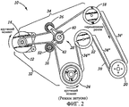
фиг.2 представляет собой схематичное изображение предпочтительного варианта осуществления конфигурации системы ременного привода вспомогательных устройств, включающей в себя электродвигатель-генератор, при этом система находится в режиме запуска;FIG. 2 is a schematic illustration of a preferred embodiment of a configuration of an auxiliary device belt drive system including an electric motor-generator, wherein the system is in a startup mode;
фиг.3 представляет собой перспективное изображение натяжного устройства, образующего часть предпочтительной системы ременного привода вспомогательных устройств, включающей в себя электродвигатель-генератор;figure 3 is a perspective image of a tensioning device forming part of a preferred belt drive system of auxiliary devices, including an electric motor-generator;
фиг.4 представляет собой перспективное изображение натяжного устройства, образующего часть предпочтительной системы ременного привода вспомогательных устройств, включающей в себя электродвигатель-генератор, при этом некоторые части на изображении удалены;4 is a perspective view of a tensioner forming part of a preferred belt drive system of auxiliary devices including an electric motor-generator, with some parts in the image removed;
фиг.5 представляет собой сечение, выполненное по линии 5-5 на фиг.3;figure 5 is a section taken along the line 5-5 in figure 3;
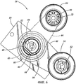
фиг.6 представляет собой вид сверху натяжного устройства, образующего часть предпочтительной системы ременного привода вспомогательных устройств, включающей в себя электродвигатель-генератор;6 is a top view of a tensioner forming part of a preferred auxiliary drive belt drive system including an electric motor-generator;
фиг.7 представляет собой сечение, выполненное по линии 7-7 на фиг.4.Fig.7 is a section taken along the line 7-7 in Fig.4.
Подробное описание предпочтительных вариантов осуществленияDetailed Description of Preferred Embodiments
Предпочтительный вариант осуществления системы 10 ременного привода вспомогательных устройств изображен на фиг.1 и 2. Она включает в себя электродвигатель-генератор 12, шкив 14 электродвигателя-генератора, шкив 18 насоса рулевого привода с усилителем, шкив 20 компрессора системы кондиционирования воздуха, шкив 22 водяного насоса, шкив 24 коленчатого вала, натяжное устройство 28 с двумя шкивами, первый шкив 16 натяжного устройства, второй шкив 26 натяжного устройства и приводной ремень 30.A preferred embodiment of the accessory
Несмотря на то, что показаны шкивы конкретных вспомогательных устройств при определенном геометрическом расположении друг относительно друга, следует понимать, что настоящее изобретение применимо для различных количеств и комбинаций вспомогательных устройств и геометрических расположений, включая как змеевидные, так и незмеевидные конфигурации, в зависимости от случая применения. Показанная конфигурация является змеевидной. Таким образом, приводной ремень 30 обычно представляет собой клиновой ремень. Однако изобретение может быть реализовано на практике при использовании в системе ремней всех типов. Кроме того, данное изображение также можно рассматривать как одну плоскость ремня/шкивов в системе ременного привода вспомогательных устройств, имеющей множество ремней.Although the pulleys of specific auxiliary devices are shown at a certain geometric arrangement relative to each other, it should be understood that the present invention is applicable to various quantities and combinations of auxiliary devices and geometric arrangements, including both serpentine and non-serpentine configurations, depending on the application . The configuration shown is serpentine. Thus, the
Стрелка, обозначенная "перемещение ремня", указывает направление перемещения ремня во время нормальной работы как в режиме генерации, так и в режиме запуска. Движение по ходу перемещения, вдоль траектории, охваченной приводным ремнем 30, означает движение в том же направлении, в котором перемещается ремень. Движение против хода перемещения означает движение в направлении, противоположном направлению перемещения ремня.The arrow labeled “belt movement” indicates the direction of movement of the belt during normal operation, both in the generation mode and in the start mode. Movement in the direction of travel along the path covered by the
При движении по ходу перемещения, начиная от шкива 24 коленчатого вала, участок 32 от коленчатого вала до электродвигателя-генератора охватывает расстояние, которое начинается в конечной точке, представляющей собой последнюю точку контакта между шкивом 24 коленчатого вала и приводным ремнем 30, и заканчивается в конечной точке, представляющей собой первую точку контакта между шкивом 14 электродвигателя-генератора и приводным ремнем 30. Первый участок 34 от электродвигателя-генератора до коленчатого вала охватывает расстояние, начинающееся в последней точке контакта между шкивом 14 электродвигателя-генератора и приводным ремнем 30 и заканчивающееся в первой точке контакта между шкивом 18 рулевого привода с усилителем и приводным ремнем 30. На фиг.1 и 2 имеются еще три участка от электродвигателя-генератора до коленчатого вала, обозначенные соответственно 34', 34'' и 34'''. Количество и местоположение участков 32 от коленчатого вала до электродвигателя-генератора и участков 34 от электродвигателя-генератора до коленчатого вала зависят от количества и местоположения шкивов вспомогательных устройств в конкретном случае применения.When moving in the direction of travel, starting from the
Направление крутящего момента на шкиве 14 электродвигателя-генератора и на шкиве 24 коленчатого вала изменяется на обратное в зависимости от режима работы системы 10 ременного привода вспомогательных устройств, как показано стрелками, обозначенными "крутящий момент", на каждом шкиве 14 и 24 соответственно на фиг.1 и 2. В режиме генерации шкив 24 коленчатого вала обеспечивает "подачу" всего вращающего момента. Шкив 22 водяного насоса, шкив 20 компрессора системы кондиционирования воздуха, шкив 18 рулевого привода с усилителем и шкив 14 электродвигателя-генератора "потребляют" вращающий момент, при этом он в незначительной степени расходуется на первом шкиве 16 натяжного устройства и втором шкиве 26 натяжного устройства. В режиме запуска шкив 14 электродвигателя-генератора обеспечивает "подачу" всего вращающего момента. Шкив 24 коленчатого вала, шкив 22 водяного насоса, шкив 20 компрессора системы кондиционирования воздуха и шкив 18 рулевого привода с усилителем "потребляют" вращающий момент, при этом он в незначительной степени расходуется на первом шкиве 16 натяжного устройства и втором шкиве 26 натяжного устройства.The direction of the torque on the
Как правило и независимо от режима работы, если предположить, что обеспечивается возможность свободного вращения каждого из шкивов, натяжение на каждом участке будет одинаковым и представлять собой статическое натяжение. Как показано на фиг.1-6, для данного предпочтительного варианта осуществления статическое натяжение представляет собой результат действия силы, приложенной к приводному ремню 30 со стороны натяжного устройства 28 посредством упругого элемента 38, действующего на комбинацию первого соединительного рычага 42 и второго соединительного рычага 44, что вызывает поджим первого шкива 16 натяжного устройства и второго шкива 26 натяжного устройства в направлении друг к другу, или взаимное смещение, и приложение усилия давления одновременно к участку 32 от коленчатого вала до электродвигателя-генератора и к участку 34 от электродвигателя-генератора до коленчатого вала, в результате чего, в свою очередь, возникает тенденция увеличения расстояния, которое приводной ремень 30 вынужден проходить вокруг всех шкивов.As a rule, and regardless of the operating mode, if we assume that the possibility of free rotation of each of the pulleys is ensured, the tension in each section will be the same and constitute static tension. As shown in FIGS. 1-6, for this preferred embodiment, the static tension is the result of the force exerted on the
При обычном режиме, или режиме генерации, изображенном на фиг.1, шкив 24 коленчатого вала "подает" вращающий момент. Последний участок 34"' от электродвигателя-генератора до коленчатого вала становится участком с наибольшим натяжением. Каждый шкив, расположенный по ходу перемещения до шкива 24 коленчатого вала, "поглощает" часть вращающего момента и вызывает уменьшение натяжения на участке, расположенном непосредственно перед ним по ходу перемещения, если не учитывать воздействия натяжного устройства. Шкив 14 электродвигателя-генератора представляет собой наибольшую нагрузку. В конце концов участок 32 от коленчатого вала до электродвигателя-генератора становится участком с наименьшим натяжением.In the normal mode, or the generation mode shown in FIG. 1, the
В режиме запуска, изображенном на фиг.2, электродвигатель-генератор 12 "подает" вращающий момент. Участок 32 от коленчатого вала до электродвигателя-генератора становится участком с наибольшим натяжением. Участок 34 от электродвигателя-генератора до коленчатого вала становится участком с наименьшим натяжением. В отличие от режима генерации шкив 24 коленчатого вала представляет собой наибольшую нагрузку. Традиционно оптимизацию компоновки привода рассматривают в зависимости от последовательности различных нагрузок и местоположения натяжного устройства. Как можно видеть, компоновка, которая обеспечивает оптимизацию в режиме генерации, существенно отличается от компоновки, которая обеспечивает оптимизацию в режиме запуска.In the startup mode shown in FIG. 2, the motor-
При проектировании обычной системы ременного привода с клиновыми ремнями, предназначенной для вспомогательных устройств, решают следующие основные задачи: 1) выбор ширины ремня (обычно обозначаемой количеством ручьев) и типа ремня в зависимости от ожидаемого крутящего момента, который должен быть создан, передан и "потреблен"; и 2) выбор статического натяжения, которое должно быть ниже, чем натяжение, приводящее к возникновению таких напряжений в ремне или компонентах системы, при которых фактический срок службы уменьшается до значений, которые меньше приемлемого срока, и выше, чем натяжение, при котором начинается неприемлемое проскальзывание. Кроме того, выбор типа и ширины ремня влияет на фактический срок службы ремня. Также следует отметить, что существует взаимозависимость между этими двумя конструктивными соображениями.When designing a conventional belt drive system with V-belts designed for auxiliary devices, the following main tasks are solved: 1) the choice of belt width (usually indicated by the number of streams) and the type of belt depending on the expected torque to be created, transmitted and consumed "; and 2) the choice of static tension, which should be lower than the tension, leading to such stresses in the belt or system components at which the actual service life is reduced to values that are less than the acceptable period and higher than the tension at which the unacceptable slip. In addition, the choice of belt type and width affects the actual life of the belt. It should also be noted that there is an interdependence between these two design considerations.
Перед конструктором систем ременного привода вспомогательных устройств неизменно стоит задача оптимального решения обеих указанных задач в свете соображений затрат и сложности. Оптимизацию выполняют путем варьирования многих геометрических параметров и связанных со свойствами материалов параметров, известных обычным специалистам в данной области техники. Одной из задач проектирования является размещение ведущих и ведомых шкивов в зависимости от момента инерции или другого момента, который создается на каждом из шкивов.The designer of auxiliary drive belt systems invariably faces the task of optimally solving both of these problems in light of cost and complexity considerations. Optimization is performed by varying many geometrical parameters and parameters associated with material properties known to those of ordinary skill in the art. One of the design tasks is the placement of the leading and driven pulleys depending on the moment of inertia or another moment that is created on each of the pulleys.
Системы привода, которые включают в себя электродвигатель-генератор, не позволяют выполнить данную определенную оптимизацию ни в каком случае, создают новые и вызывающие трудности ограничения, и до сих пор подразумевалась их оптимизация при практической реализации. Причина трудностей состоит в том, что шкивы, которые "подают" вращающий момент и являются источником наибольшего момента инерции, различаются в зависимости от режима работы. Кроме того, создаются большие нагрузки, обусловленные моментом инерции, чем те, с которыми сталкиваются в обычных системах привода.Drive systems, which include an electric motor-generator, do not allow this specific optimization to be performed in any case, create new and difficult constraints, and their optimization in practical implementation was still implied. The reason for the difficulties is that the pulleys that “deliver” torque and are the source of the greatest moment of inertia differ depending on the mode of operation. In addition, greater loads are created due to the moment of inertia than those encountered in conventional drive systems.
Натяжное устройство 28 с двумя шкивами, поджимаемыми в направлении друг к другу, по настоящему изобретению позволяет в значительной степени оптимизировать систему 10 ременного привода вспомогательных устройств в определенных случаях применения для комбинации режимов, в частности при использовании системы с компоновкой по предпочтительному варианту осуществления.The
Как показано на фиг.3-6, натяжное устройство 28 содержит первый шкив 16 натяжного устройства, второй шкив 26 натяжного устройства, упругий элемент 38, цапфу (ось шарнирной опоры) 40, первый соединительный рычаг 42 и второй соединительный рычаг 44, демпфирующую колодку 46, кольцевую поверхность 48 демпфирующего механизма, установочную (базовую) плиту 50, болт 52 первого шкива, болт 54 второго шкива, втулку 56, прокладку 57, поворотную опору 58, втулочную часть 60 первого рычага и втулочную часть 62 второго рычага. Первый и второй шкивы 16 и 26 шарнирно установлены соответственно на первом и втором соединительных рычагах 42 и 44 с помощью шарикоподшипников. Шарикоподшипники включают в себя [шаровые] опоры 70 и кольца 72.As shown in FIGS. 3-6, the
Первый и второй соединительные рычаги, обозначенные соответственно 42 и 44, шарнирно установлены с возможностью поворота на поворотной опоре 58, при этом они опираются на втулку 56 и прокладку 57. Втулочная часть 60 первого рычага и втулочная часть 62 второго рычага соприкасаются с втулкой 56 и прокладкой 57, которые, в свою очередь, соприкасаются с поворотной опорой 58 и цапфой 40. Подразумевается, что каждый из элементов может иметь посадку, приводящую к значительному трению. Такое трение обеспечивает дополнительное демпфирование обоих соединительных рычагов, то есть соответственно первого и второго соединительных рычагов 42 и 44, относительно установочной плиты 50, которая закреплена в точке, неподвижной относительно блока цилиндров двигателя (непоказанного).The first and second connecting levers, designated 42 and 44, respectively, are pivotally mounted to rotate on the pivot bearing 58, while they rest on the
Несмотря на то, что первый и второй соединительные рычаги 42 и 44 могут поворачиваться относительно установочной плиты, они не могут поворачиваться друг относительно друга. Вместо этого они поджимаются друг к другу под действием усилия, прилагаемого к ним со стороны упругого элемента 38, при этом данное усилие изменяется посредством демпфирующего механизма, включающего в себя демпфирующую колодку 46, скользящую по кольцевой поверхности 48 демпфирующего механизма, образованной на внутренней поверхности втулочной части 62 второго рычага. Трение, возникающее при контакте демпфирующей колодки 46 и кольцевой поверхности 48 демпфирующего механизма, обеспечивает демпфирование перемещений первого и второго соединительных рычагов 42 и 44, но только относительно друг друга.Although the first and second connecting
Упругий элемент 38, в данном предпочтительном варианте осуществления представляющий собой стальную пружину, работающую на кручение, присоединен не напрямую к первому соединительному рычагу 42, а через посредство демпфирующей колодки 46 и упорного элемента 64 для демпфирующей колодки в точке 66 присоединения демпфирующей колодки к пружине и присоединен непосредственно ко второму соединительному рычагу 42 в точке 68 присоединения второго рычага к пружине. Упругий элемент 38 намотан с возможностью передачи крутящего момента второму соединительному рычагу 44 в направлении по часовой стрелке, если смотреть на фиг.4, и передачи крутящего момента демпфирующей колодке 46 в направлении против часовой стрелки, если смотреть на фиг.6. Действующий против часовой стрелки крутящий момент, переданный демпфирующей колодке 46, передается упорному элементу 64 для демпфирующей колодки и, тем самым, первому соединительному рычагу 42, к которому присоединен упорный элемент 64 для демпфирующей колодки.The
В данном предпочтительном варианте осуществления любое демпфирование, обеспечиваемое относительно установочной плиты 50 за счет точной посадки втулочной части 60 первого рычага, втулочной части 62 второго рычага, втулки 56, прокладки 57, поворотной опоры 58 и цапфы 40, является симметричным. Неподвижная посадка данного типа также обеспечивает дополнительную составляющую усилия, обеспечивающего симметричный поджим, которая дополняет демпфирование первого соединительного рычага 42 относительно второго соединительного рычага 44. Следует понимать, что даже симметричное демпфирование приводит к несимметричному поджиму, поскольку демпфирующие силы приводят к увеличению суммарных усилий поджима в одном направлении и уменьшению их в другом направлении.In this preferred embodiment, any damping provided relative to the mounting
Демпфирующая сила, создаваемая между первым и вторым соединительными рычагами 42 и 44, имеет несимметричную составляющую, так что совместное перемещение первого и второго шкивов 16 и 26 демпфируется в большей степени при смещении их в сторону друг от друга, чем при смещении их в направлении друг к другу. Это имеет место независимо от того, смещаются ли первый или второй шкив 16 и 26 в направлении усиления или ослабления натяжения ремня. Если рассматривать каждый из первого и второго шкивов 16 и 26 по отдельности, то направление ослабления натяжения ремня для любого из двух шкивов - первого шкива 16 или второго шкива 26 - представляет собой такое направление, при котором обеспечивается возможность схватывания ремнем 30 меньшей траектории. Направление усиления натяжения ремня представляет собой просто противоположное направление. Однако при рассмотрении перемещения первого и второго шкивов 16 и 26 направление ослабления натяжения ремня - это такое направление, когда первый и второй шкивы 16 и 26 смещаются дальше друг от друга. Усиление натяжения ремня в данном случае также просто соответствует обратной ситуации.The damping force created between the first and second connecting
Как показано на фиг.7, концевая часть 67 пружины, соединенная с колодкой, имеет ось А изгиба. Делящий пополам радиус В проходит от центра поворотной опоры 58 через среднюю точку контакта между демпфирующей колодкой 46 и кольцевой поверхностью 48 демпфирующего механизма. Хорда С перпендикулярна радиусу В и проходит через две крайние точки контакта между демпфирующей колодкой 46 и кольцевой поверхностью 48 демпфирующего механизма. Как можно видеть, ось А изгиба пересекается с хордой С под углом X, и, таким образом, она не параллельна хорде С. Расстояние от точки контакта концевой части 67 пружины, соединенной с колодкой, с поворотной опорой 58, которая обозначена как точка Р поворота, до средней точки контакта между демпфирующей колодкой 46 и кольцевой поверхностью 48 демпфирующего механизма представляет собой фиксированное расстояние R1. Угол Х приводит к асимметрии демпфирования между первым и вторым соединительными рычагами 42 и 44. В состоянии покоя концевая часть 67 пружины, соединенная с колодкой, и демпфирующая колодка 46 проходят на фиксированное расстояние R1, равное расстоянию "исполнения" R2, в результате чего они контактируют с кольцевой поверхностью 48 демпфирующего механизма с полным усилием, создаваемым упругим элементом 38.As shown in FIG. 7, the
Когда первый и второй шкивы 16 и 26 смещаются в сторону друг друга, то есть в направлении усиления натяжения ремня, кольцевая поверхность 48 демпфирующего механизма смещается по часовой стрелке относительно первого соединительного рычага 42. Это, в свою очередь, приводит к смещению демпфирующей колодки 46 и соединенной с колодкой концевой части 67 пружины в направлении по часовой стрелке вокруг точки Р поворота. Это приводит к соответствующей тенденции смещения расстояния "исполнения" R2 по часовой стрелке. Как можно видеть, это приводит к тенденции увеличения расстояния "исполнения" R2. Однако фиксированное расстояние R1 не может увеличиться. Таким образом, демпфирующая колодка 46 будет стремиться к отрыву от кольцевой поверхности 48 демпфирующего механизма, при этом она "поглощает" некоторую часть усилия, в противном случае обеспечиваемого упругим элементом 38. Трение на поверхности демпфирующей колодки 46 и кольцевой поверхности 48 демпфирующего механизма уменьшается, что приводит к уменьшению демпфирования в направлении усиления натяжения ремня.When the first and
Когда первый и второй шкивы 16 и 26 смещаются в сторону друг от друга, то есть в направлении ослабления натяжения ремня, кольцевая поверхность 48 демпфирующего механизма смещается в направлении против часовой стрелки относительно первого соединительного рычага 42. Это, в свою очередь, приводит к смещению демпфирующей колодки 46 и соединенной с колодкой концевой части 67 пружины в направлении против часовой стрелки вокруг точки Р поворота. Это приводит к соответствующей тенденции смещения расстояния "исполнения" R2 против часовой стрелки. Как можно видеть, это приводит к тенденции уменьшения расстояния "исполнения" R2. Однако фиксированное расстояние R1 не может уменьшиться. Таким образом, демпфирующая колодка 46 будет стремиться прижаться к кольцевой поверхности 48 демпфирующего механизма, дополняя усилие, создаваемое упругим элементом 38. Трение на поверхности демпфирующей колодки 46 и кольцевой поверхности 48 демпфирующего механизма увеличивается, что приводит к увеличению демпфирования в направлении усиления натяжения ремня.When the first and
Как рассмотрено выше, при переходе систем от работы в статическом состоянии к режиму генерации все участки 34, 34', 34'' и 34''' от коленчатого вала до электродвигателя-генератора будут находиться под большим натяжением по сравнению с участком 32 от электродвигателя-генератора до коленчатого вала. Таким образом, усилие, вызывающее выпрямление участка 34 от коленчатого вала до электродвигателя-генератора, будет больше усилия, вызывающего выпрямление участка 32 от электродвигателя-генератора до коленчатого вала. В предпочтительном варианте осуществления, изображенном на фиг.1, это вызывает принудительное смещение второго соединительного рычага 44 и связанного с ним второго шкива 26 натяжного устройства в положение, которое позволяет приводному ремню 30 на участке 34 от коленчатого вала до электродвигателя генератора проходить по траектории наименьшей возможной длины. Как показано, это равнозначно ситуации, при которой второй соединительный рычаг 44 принимает положение, при котором он по существу перпендикулярен выпрямленному приводному ремню 30 на участке 34 от коленчатого вала до электродвигателя-генератора. При данной конкретной геометрии обеспечивается достижение вторым шкивом 26 натяжного устройства предела его перемещения в направлении ослабления натяжения ремня при одновременном отклонении приводного ремня 30, и такая геометрия является наиболее предпочтительной. Однако также предусмотрено, что в менее предпочтительном варианте осуществления поворот второго соединительного рычага 44 вокруг основной оси 40 поворота может быть ограничен за счет установки упоров. Тем не менее, также подразумевается, что размещение основной оси 40 поворота совместно со вторым соединительным рычагом 44 определенной длины может быть таким, что участок 34 от коленчатого вала до электродвигателя-генератора может стать прямолинейным до того, как второй шкив 26 натяжного устройства достигнет конца своего хода перемещения. В любом из указанных случаев приводной ремень 30 будет проходить по самой короткой возможной траектории на участке 34 от коленчатого вала до электродвигателя-генератора.As discussed above, during the transition of systems from operation in a static state to the generation mode, all
Если бы это изменение положения на участке 34 от коленчатого вала до электродвигателя-генератора происходило без другого соответствующего события, статическое натяжение в системе 10 ременного привода уменьшилось бы. Однако поворот второго соединительного рычага 44 вокруг основной оси 40 поворота создает напряжение в упругом элементе 38, что, в свою очередь, приводит к увеличению усилия поджима, действующего на первый соединительный рычаг 42. Это вызывает соответствующее увеличение усилия натяжения, создаваемого с помощью первого шкива 16 натяжного устройства на приводном ремне 30 на участке 32 от электродвигателя-генератора до коленчатого вала. Соответственно, статическое натяжение приводного ремня 30 остается в значительной степени неизменным при переключении режимов работы со статического, или режима без движения, на режим генерации. Анализ будет таким же при переключении режимов работы с запуска на генерацию.If this change in position in the
При переключении с режима генерации на режим запуска имеет место противоположная ситуация. То есть, первый шкив 16 натяжного устройства достигает предела своего перемещения в направлении ослабления натяжения. Усилие натяжения на втором шкиве 26 натяжного устройства увеличивается. Статическое натяжение приводного ремня 30 остается в значительной степени неизменным.When switching from the generation mode to the start mode, the opposite situation takes place. That is, the
Настоящее изобретение, раскрытое с помощью описанных вариантов осуществления, позволяет выполнить существенную оптимизацию эксплуатационных качеств и рабочих характеристик в долгосрочном и краткосрочном периодах и выбрать ремень оптимальным образом, при этом одновременно оно позволяет в значительной степени снизить затраты и сложность и улучшить способность приспосабливания к тем системам стартеров-генераторов, для которых оно может быть применено.The present invention, disclosed using the described embodiments, allows for significant optimization of long-term and short-term performance and performance and to choose the belt in an optimal way, while at the same time it can significantly reduce costs and complexity and improve the ability to adapt to those starter systems generators for which it can be applied.
Вышеприведенное описание и иллюстративные примеры осуществления настоящего изобретения были проиллюстрированы на чертежах и подробно описаны, при этом были приведены различные модификации и альтернативные варианты осуществления. Однако следует понимать, что представленное выше описание изобретения приведено только в качестве примера и что объем изобретения должен быть ограничен только формулой изобретения, интерпретируемой с учетом известного уровня техники. Более того, изобретение, раскрытое здесь с помощью иллюстративных примеров, может быть реализовано на практике при отсутствии любого элемента, что не раскрыто здесь конкретно.The above description and illustrative embodiments of the present invention have been illustrated in the drawings and described in detail, with various modifications and alternative embodiments being given. However, it should be understood that the above description of the invention is given only as an example and that the scope of the invention should be limited only by the claims, interpreted in view of the prior art. Moreover, the invention disclosed here using illustrative examples can be practiced in the absence of any element, which is not specifically disclosed here.
Claims (7)
Applications Claiming Priority (2)
| Application Number | Priority Date | Filing Date | Title |
|---|---|---|---|
| US23761400P | 2000-10-03 | 2000-10-03 | |
| US60/237,614 | 2000-10-03 |
Publications (2)
| Publication Number | Publication Date |
|---|---|
| RU2003112681A RU2003112681A (en) | 2004-09-10 |
| RU2266445C2 true RU2266445C2 (en) | 2005-12-20 |
Family
ID=22894454
Family Applications (1)
| Application Number | Title | Priority Date | Filing Date |
|---|---|---|---|
| RU2003112681/11A RU2266445C2 (en) | 2000-10-03 | 2001-10-01 | Tension device for belt drive of auxiliary members |
Country Status (16)
| Country | Link |
|---|---|
| US (1) | US20020039944A1 (en) |
| EP (1) | EP1322874B1 (en) |
| JP (1) | JP4133320B2 (en) |
| KR (1) | KR100729296B1 (en) |
| CN (1) | CN1278060C (en) |
| AT (1) | ATE382809T1 (en) |
| AU (1) | AU2001296474A1 (en) |
| BR (1) | BR0114360B1 (en) |
| CA (1) | CA2424256C (en) |
| DE (1) | DE60132222T2 (en) |
| ES (1) | ES2295214T3 (en) |
| HK (1) | HK1052959A1 (en) |
| MX (1) | MXPA03003936A (en) |
| PL (1) | PL366033A1 (en) |
| RU (1) | RU2266445C2 (en) |
| WO (1) | WO2002029279A2 (en) |
Cited By (1)
| Publication number | Priority date | Publication date | Assignee | Title |
|---|---|---|---|---|
| RU192452U1 (en) * | 2019-04-11 | 2019-09-17 | Общество с ограниченной ответственностью "Комбайновый завод "Ростсельмаш" | BELT TENSION MECHANISM |
Families Citing this family (82)
| Publication number | Priority date | Publication date | Assignee | Title |
|---|---|---|---|---|
| US7086373B2 (en) * | 2002-11-01 | 2006-08-08 | The Gates Corporation | Damped accessory drive system including a motor/generator |
| US6689001B2 (en) * | 2001-12-12 | 2004-02-10 | Dayco Products, Llc | Adaptive belt tensioner system for control of reversible torque load pulley |
| US6652401B2 (en) * | 2002-02-11 | 2003-11-25 | The Gates Corporation | Method of tuning a belt drive system |
| US6830524B2 (en) * | 2002-05-23 | 2004-12-14 | General Motors Corporation | Crank drive belt system with triple pulley tensioner |
| US6817328B2 (en) * | 2002-09-11 | 2004-11-16 | Daimlerchrysler Corporation | Belt driven engine starter motor system |
| US20040077446A1 (en) * | 2002-10-22 | 2004-04-22 | Dana Corporation | Belt tensioner assembly for internal combustion engine |
| DE10253241A1 (en) * | 2002-11-15 | 2004-05-27 | Ina-Schaeffler Kg | Clamping device for a traction mechanism drive |
| ITTO20021133A1 (en) * | 2002-12-30 | 2004-06-30 | Dayco Europe Srl | TWO-ARM TENSIONER FOR A BELT DRIVE. |
| DE10321801A1 (en) * | 2003-01-10 | 2004-07-29 | Muhr Und Bender Kg | Belt tensioner |
| EP1437528B1 (en) * | 2003-01-10 | 2010-03-10 | Muhr und Bender KG | Belt tensioner |
| ES2306849T3 (en) * | 2003-04-02 | 2008-11-16 | Dayco Europe S.R.L. | TWO ARM BELT TENSIONER. |
| ITTO20030819A1 (en) * | 2003-10-17 | 2005-04-18 | Dayco Europe Srl | BI-ARM TENSIONER FOR A TRANSMISSION BELT OF A MOTOR VEHICLE. |
| DE602004020057D1 (en) * | 2004-05-14 | 2009-04-30 | Dayco Europe Srl | Tensioning device with torsion bar and damping element for motor vehicle belt drive |
| AT501482B8 (en) * | 2004-05-26 | 2007-02-15 | Gfm Beteiligungs & Man Gmbh | DEVICE FOR INTERMITTENTLY DRIVING A SPINDLE FOR A WORKPIECE BRACKET, ESPECIALLY A FORGING MACHINE |
| DE102004029829A1 (en) * | 2004-06-19 | 2005-12-29 | Daimlerchrysler Ag | Belt tensioning device and belt transmission with such a belt tensioning device |
| US7479078B2 (en) * | 2004-11-17 | 2009-01-20 | Dayco Products, Llc | Belt tensioner system |
| US7494434B2 (en) * | 2005-06-15 | 2009-02-24 | Gm Global Technology Operations, Inc. | Belt alternator starter accessory drive with dual tensioner |
| DE102005039719A1 (en) * | 2005-08-23 | 2007-03-22 | Schaeffler Kg | Tensioning system for traction mechanism drive, has two tensioning devices supported rotatably around rotation axis, where two clamping devices are movably coupled with one another for simultaneously aligned movement |
| JP5242544B2 (en) | 2006-03-22 | 2013-07-24 | ライテンズ オートモーティブ パートナーシップ | Flexible drive tensioner |
| DE102006014942A1 (en) * | 2006-03-31 | 2007-10-04 | Schaeffler Kg | Clamping device for use in traction mechanism drive, has coil spring, where tilting moment of spring force of spring and resultant reaction force of drive mutually suspend rotary axis of swivel bearing around imaginary slide tilting axis |
| DE102006017287B4 (en) | 2006-04-12 | 2021-03-25 | Litens Automotive Gmbh | Tensioner for an endless drive |
| CN101785195A (en) * | 2007-07-09 | 2010-07-21 | 株式会社世联 | Actuator and spring used therefor |
| US7874951B2 (en) * | 2008-03-14 | 2011-01-25 | Jenny Products, Incorporated | Motor to accessory drive system |
| DE102008025552B4 (en) * | 2008-05-28 | 2020-06-10 | Muhr Und Bender Kg | Belt tensioner for starter-generator application |
| EP2297479B1 (en) * | 2008-06-19 | 2019-01-09 | Dayco Europe S.R.L. | Starter alternator assembly comprising a poly-v belt and poly-v belt |
| JP5469326B2 (en) * | 2008-09-29 | 2014-04-16 | ボーグワーナー インコーポレーテッド | Tensioning device |
| WO2010037232A1 (en) | 2008-10-02 | 2010-04-08 | Litens Automotive Partnership | Compact tensioner with sustainable damping |
| US8408188B1 (en) * | 2008-12-12 | 2013-04-02 | Hormilla Performance Engineering LLC | Engine accessory belt drive pulley |
| US8092328B2 (en) | 2009-06-30 | 2012-01-10 | The Gates Corporation | Dual tensioner assembly |
| US8602930B2 (en) * | 2009-09-18 | 2013-12-10 | GM Global Technology Operations LLC | Drive belt tensioner for motor generator unit |
| US9133762B2 (en) * | 2009-09-18 | 2015-09-15 | GM Global Technology Operations LLC | Drive belt tensioner for motor generator unit |
| DE102010019613B4 (en) * | 2010-05-06 | 2019-02-21 | Litens Automotive Gmbh | Spanner and endless drive assembly |
| CN101934731B (en) * | 2010-08-24 | 2013-01-23 | 上海中科深江电动车辆有限公司 | Integrated accessory force taking device special for complete electric vehicle |
| DE102011082764A1 (en) * | 2010-10-13 | 2012-04-19 | Schaeffler Technologies Gmbh & Co. Kg | Clamping device for a traction mechanism drive of an internal combustion engine |
| JP5627621B2 (en) * | 2011-04-28 | 2014-11-19 | 三ツ星ベルト株式会社 | Auto tensioner |
| US9341243B2 (en) | 2012-03-29 | 2016-05-17 | Litens Automotive Partnership | Tensioner and endless drive arrangement |
| GB2507985B (en) * | 2012-11-15 | 2018-06-13 | Ford Global Tech Llc | A method for controlling an engine drive belt tensioner system |
| JP2016503151A (en) | 2012-12-26 | 2016-02-01 | リテンズ オートモーティヴ パートナーシップ | Orbital tensioner assembly |
| DE102013002993A1 (en) * | 2013-02-22 | 2014-08-28 | Schaeffler Technologies Gmbh & Co. Kg | Starter Generator - Belt Tensioner |
| DE102013203957B3 (en) * | 2013-03-08 | 2014-02-13 | Schaeffler Technologies AG & Co. KG | Belt tensioner for mounting at generator of aggregate drive of internal combustion engine, has lever comprising steel core with aluminum sleeve, which encloses outside of cavity and completely encloses running part of core within bearing |
| CN103645050B (en) * | 2013-11-19 | 2016-08-17 | 合肥京东方光电科技有限公司 | The belt of a kind of transmission device is fixed and comes off detection equipment |
| JP6248595B2 (en) * | 2013-12-10 | 2017-12-20 | 三菱自動車工業株式会社 | Belt tension adjustment mechanism |
| JP6252206B2 (en) * | 2014-01-29 | 2017-12-27 | 株式会社デンソー | Transmission system |
| US20150300462A1 (en) * | 2014-02-06 | 2015-10-22 | Gates Corporation | Tensioner |
| US9140338B2 (en) * | 2014-02-06 | 2015-09-22 | Gates Corporation | Tensioner |
| US9920819B2 (en) * | 2014-02-06 | 2018-03-20 | Gates Corporation | Tensioner |
| JPWO2015177997A1 (en) * | 2014-05-22 | 2017-04-20 | バンドー化学株式会社 | Belt transmission system |
| JP6452191B2 (en) * | 2014-06-26 | 2019-01-16 | ダイハツ工業株式会社 | Internal combustion engine for vehicles |
| US20170138445A1 (en) * | 2014-06-27 | 2017-05-18 | Litens Automotive Partnership | Endless drive arrangement with active idler |
| EP3209902A4 (en) * | 2014-10-20 | 2018-05-30 | Litens Automotive Partnership | Endless drive arrangement with tensioning system and isolation device |
| US9651122B2 (en) | 2015-02-05 | 2017-05-16 | Gates Corporation | Dual arm tensioner |
| KR101664672B1 (en) * | 2015-03-20 | 2016-10-10 | 현대자동차주식회사 | Belt auto-tensioner for engine |
| WO2016181619A1 (en) * | 2015-05-08 | 2016-11-17 | バンドー化学株式会社 | Belt transmission system |
| FR3039874B1 (en) * | 2015-08-03 | 2017-08-25 | Peugeot Citroen Automobiles Sa | ASSEMBLY COMPRISING AN ENGINE ACCESSORY, A BELT TENSIONER, A FIXING BRACKET AND COMMON CLAMPING MEANS BETWEEN THEM |
| DE102015013560A1 (en) * | 2015-10-20 | 2017-04-20 | Saurer Germany Gmbh & Co. Kg | Press roller unit for a spinning or twisting machine |
| US10619521B2 (en) | 2015-12-21 | 2020-04-14 | Cummins Inc. | Waste heat recovery power drive |
| WO2017205976A1 (en) * | 2016-05-30 | 2017-12-07 | Litens Automotive Partnership | Endless drive arrangement and tensioning system for same |
| CN106090156B (en) * | 2016-06-21 | 2018-12-04 | 宁波丰茂远东橡胶有限公司 | A kind of two-way tensioning apparatus of bi-directional association and belt variable damping unit |
| DE102016211405B4 (en) * | 2016-06-24 | 2018-08-16 | Ford Global Technologies, Llc | Tension pulley arrangement for a belt drive and belt drive comprising the tension pulley arrangement |
| US10066708B2 (en) * | 2016-08-04 | 2018-09-04 | Ford Global Technologies, Llc | External spring to increase tension on belt tensioner for internal combustion engine |
| EP3513097B1 (en) * | 2016-09-13 | 2022-03-23 | Litens Automotive Partnership | V tensioner and endless drive arrangement |
| US9890837B1 (en) * | 2016-09-15 | 2018-02-13 | Gates Corporation | Tensioner |
| US10245971B2 (en) * | 2017-03-06 | 2019-04-02 | Gates Corporation | Motor-generator system |
| DE102017107047A1 (en) * | 2017-03-31 | 2018-10-04 | Muhr Und Bender Kg | Clamping device with adjusting mechanism and method for adjusting the torque of the clamping device |
| US10962092B2 (en) * | 2017-09-08 | 2021-03-30 | Gates Corporation | Tensioner and method |
| DE102017218040A1 (en) * | 2017-10-10 | 2019-04-11 | Volkswagen Aktiengesellschaft | Clamping device for a starter generator of an internal combustion engine and a traction mechanism drive with such a clamping device |
| CN109667897A (en) * | 2017-10-13 | 2019-04-23 | 舍弗勒技术股份两合公司 | Mechanical tensioner with torsion spring |
| DE102017124783B3 (en) * | 2017-10-24 | 2019-03-21 | Muhr Und Bender Kg | jig |
| USD855079S1 (en) * | 2017-11-10 | 2019-07-30 | Zeta-Sassi Srl | Tension device |
| US10746264B2 (en) * | 2017-11-16 | 2020-08-18 | Gates Corporation | Rotary tensioner |
| TWI651481B (en) * | 2017-11-24 | 2019-02-21 | 上銀科技股份有限公司 | Double belt drive |
| CN107965554A (en) * | 2017-12-28 | 2018-04-27 | 东风商用车有限公司 | A kind of compound tensioning wheel |
| US10876606B2 (en) * | 2018-03-13 | 2020-12-29 | Gates Corporation | Orbital tensioner |
| US10774906B2 (en) | 2018-03-27 | 2020-09-15 | Gates Corporation | Tensioner |
| US11041548B2 (en) * | 2018-08-08 | 2021-06-22 | Ford Global Technologies, Llc | Belt tensioning system and belt tensioning method |
| KR102552020B1 (en) * | 2018-10-19 | 2023-07-05 | 현대자동차 주식회사 | Tensioner for hybrid electric vehicle |
| CN109139832B (en) * | 2018-10-29 | 2020-11-10 | 义乌吉利发动机有限公司 | Belt tensioning device and vehicle |
| CN111486203B (en) * | 2019-01-25 | 2021-10-29 | 长城汽车股份有限公司 | Belt tensioning mechanism |
| CN111120132B (en) * | 2019-12-11 | 2022-04-19 | 宁波吉利罗佑发动机零部件有限公司 | Method and system for adjusting oil injection quantity according to axial force of belt pulley |
| WO2021187482A1 (en) * | 2020-03-18 | 2021-09-23 | Ntn株式会社 | Auxiliary belt auto tensioner and auxiliary drive system |
| DE102020004335A1 (en) * | 2020-07-20 | 2022-01-20 | Muhr Und Bender Kg | Belt tensioning device and belt drive with such a belt tensioning device |
| US20220099165A1 (en) * | 2020-09-28 | 2022-03-31 | Caterpillar Inc. | Engine accessory drive system and one-piece bracket for same |
Family Cites Families (6)
| Publication number | Priority date | Publication date | Assignee | Title |
|---|---|---|---|---|
| US4758208A (en) | 1987-07-13 | 1988-07-19 | General Motors Corporation | Automatic belt tensioner for vehicle combined starter-generator |
| DE4243451A1 (en) * | 1992-12-22 | 1994-06-23 | Schaeffler Waelzlager Kg | Tensioner for belt or chain in combustion IC-engine |
| US5935032A (en) | 1998-06-02 | 1999-08-10 | The Gates Corporation | Tensioner with second pivot-arm for damping mechanism |
| DE19849659A1 (en) * | 1998-10-29 | 2000-05-04 | Schaeffler Waelzlager Ohg | Tensioning device for a traction device |
| DE19926612A1 (en) * | 1999-06-11 | 2000-12-14 | Schaeffler Waelzlager Ohg | Belt drive of an internal combustion engine |
| DE10044645A1 (en) * | 2000-09-08 | 2002-03-21 | Schaeffler Waelzlager Ohg | Traction drive, especially for driving internal combustion engine units, has arrangement for demand regulated setting of tension consisting of unit with housing with limited rotation and pulley |
-
2001
- 2001-10-01 AU AU2001296474A patent/AU2001296474A1/en not_active Abandoned
- 2001-10-01 EP EP01977348A patent/EP1322874B1/en not_active Expired - Lifetime
- 2001-10-01 CA CA002424256A patent/CA2424256C/en not_active Expired - Fee Related
- 2001-10-01 AT AT01977348T patent/ATE382809T1/en not_active IP Right Cessation
- 2001-10-01 KR KR1020037004692A patent/KR100729296B1/en not_active IP Right Cessation
- 2001-10-01 DE DE60132222T patent/DE60132222T2/en not_active Expired - Lifetime
- 2001-10-01 WO PCT/US2001/030772 patent/WO2002029279A2/en active IP Right Grant
- 2001-10-01 CN CNB018167713A patent/CN1278060C/en not_active Expired - Fee Related
- 2001-10-01 PL PL01366033A patent/PL366033A1/en unknown
- 2001-10-01 BR BRPI0114360-3A patent/BR0114360B1/en not_active IP Right Cessation
- 2001-10-01 ES ES01977348T patent/ES2295214T3/en not_active Expired - Lifetime
- 2001-10-01 RU RU2003112681/11A patent/RU2266445C2/en active
- 2001-10-01 US US09/969,205 patent/US20020039944A1/en not_active Abandoned
- 2001-10-01 JP JP2002532822A patent/JP4133320B2/en not_active Expired - Fee Related
- 2001-10-01 MX MXPA03003936A patent/MXPA03003936A/en not_active Application Discontinuation
-
2003
- 2003-07-18 HK HK03105217A patent/HK1052959A1/en not_active IP Right Cessation
Cited By (1)
| Publication number | Priority date | Publication date | Assignee | Title |
|---|---|---|---|---|
| RU192452U1 (en) * | 2019-04-11 | 2019-09-17 | Общество с ограниченной ответственностью "Комбайновый завод "Ростсельмаш" | BELT TENSION MECHANISM |
Also Published As
| Publication number | Publication date |
|---|---|
| WO2002029279A3 (en) | 2003-02-27 |
| CN1278060C (en) | 2006-10-04 |
| PL366033A1 (en) | 2005-01-24 |
| EP1322874B1 (en) | 2008-01-02 |
| ATE382809T1 (en) | 2008-01-15 |
| WO2002029279A2 (en) | 2002-04-11 |
| CN1468347A (en) | 2004-01-14 |
| US20020039944A1 (en) | 2002-04-04 |
| CA2424256C (en) | 2007-07-10 |
| MXPA03003936A (en) | 2003-08-19 |
| BR0114360B1 (en) | 2009-08-11 |
| DE60132222T2 (en) | 2008-12-18 |
| HK1052959A1 (en) | 2003-10-03 |
| DE60132222D1 (en) | 2008-02-14 |
| CA2424256A1 (en) | 2002-04-11 |
| BR0114360A (en) | 2005-01-11 |
| JP4133320B2 (en) | 2008-08-13 |
| AU2001296474A1 (en) | 2002-04-15 |
| JP2004515721A (en) | 2004-05-27 |
| ES2295214T3 (en) | 2008-04-16 |
| EP1322874A2 (en) | 2003-07-02 |
| KR100729296B1 (en) | 2007-06-18 |
| KR20030069998A (en) | 2003-08-27 |
Similar Documents
| Publication | Publication Date | Title |
|---|---|---|
| RU2266445C2 (en) | Tension device for belt drive of auxiliary members | |
| US6506137B2 (en) | Tension device for a flexible drive element | |
| RU2240452C1 (en) | Belt tensioning twin linear device | |
| JP5349497B2 (en) | Torsional decoupler | |
| US7530911B2 (en) | Travel limited linear belt tensioner | |
| JP7404505B2 (en) | orbital tensioner | |
| US7552708B2 (en) | Damped accessory drive system including a motor/generator | |
| EP1334290B1 (en) | Accessory drive system including a motor/generator | |
| AU2001294957A1 (en) | Dual linear belt tensioner | |
| JP2007530857A (en) | Dual ratio belt drive system | |
| JP2004510931A (en) | Motor / generator and auxiliary belt transmission system | |
| AU2001296616A1 (en) | Accessory drive system including a motor/generator | |
| RU2302570C2 (en) | Auxiliary dampable drive system including electric motor/generator |