RU2264503C1 - Device for laying watertight film curtain - Google Patents
Device for laying watertight film curtain Download PDFInfo
- Publication number
- RU2264503C1 RU2264503C1 RU2004122378/03A RU2004122378A RU2264503C1 RU 2264503 C1 RU2264503 C1 RU 2264503C1 RU 2004122378/03 A RU2004122378/03 A RU 2004122378/03A RU 2004122378 A RU2004122378 A RU 2004122378A RU 2264503 C1 RU2264503 C1 RU 2264503C1
- Authority
- RU
- Russia
- Prior art keywords
- film
- chamber
- hopper
- guide chamber
- laying
- Prior art date
Links
- 239000000853 adhesive Substances 0.000 claims abstract description 9
- 230000001070 adhesive effect Effects 0.000 claims abstract description 9
- 239000011248 coating agent Substances 0.000 claims abstract description 6
- 238000000576 coating method Methods 0.000 claims abstract description 6
- 239000007788 liquid Substances 0.000 claims abstract description 3
- 239000002689 soil Substances 0.000 claims description 24
- 230000000694 effects Effects 0.000 abstract description 4
- 238000011068 loading method Methods 0.000 abstract description 3
- 230000013011 mating Effects 0.000 abstract description 3
- 239000000126 substance Substances 0.000 abstract description 2
- 238000009825 accumulation Methods 0.000 abstract 1
- 238000005452 bending Methods 0.000 description 2
- 230000003068 static effect Effects 0.000 description 2
- 238000003466 welding Methods 0.000 description 2
- 238000013459 approach Methods 0.000 description 1
- 239000013590 bulk material Substances 0.000 description 1
- 238000006243 chemical reaction Methods 0.000 description 1
- 239000004927 clay Substances 0.000 description 1
- 230000021615 conjugation Effects 0.000 description 1
- 238000013016 damping Methods 0.000 description 1
- 238000005516 engineering process Methods 0.000 description 1
- 238000002474 experimental method Methods 0.000 description 1
- 238000011049 filling Methods 0.000 description 1
- 238000001914 filtration Methods 0.000 description 1
- 239000012530 fluid Substances 0.000 description 1
- 230000005484 gravity Effects 0.000 description 1
- 238000009434 installation Methods 0.000 description 1
- 238000009940 knitting Methods 0.000 description 1
- 239000000463 material Substances 0.000 description 1
- 239000002184 metal Substances 0.000 description 1
- 230000035699 permeability Effects 0.000 description 1
- 238000001556 precipitation Methods 0.000 description 1
- 230000005855 radiation Effects 0.000 description 1
- 238000007789 sealing Methods 0.000 description 1
- 239000011343 solid material Substances 0.000 description 1
- 229920006302 stretch film Polymers 0.000 description 1
- 230000001960 triggered effect Effects 0.000 description 1
Images


Landscapes
- Bulkheads Adapted To Foundation Construction (AREA)
Abstract
Description
Изобретение относится к гидротехническому строительству и может быть использовано для укладки противофильтрационной пленочной завесы на поверхностях любой ориентации от горизонтальной или слабонаклоненной до вертикальной.The invention relates to hydraulic engineering and can be used for laying a film curtain on surfaces of any orientation from horizontal or slightly inclined to vertical.
Известно устройство для создания противофильтрационного экрана, состоящее из поводка, который содержит периодически расставленные по его длине скобы со спицами и может приводиться в движение различными средствами механизированной укладки экранов (патент РФ №2022090, Кл. Е 02 В 3/16, 1994).A device for creating an anti-filter screen, consisting of a leash, which contains periodically spaced along its length staples with knitting needles and can be set in motion by various means of mechanized styling of screens (RF patent No. 2202090, CL. E 02
Недостатки указанного устройства заключаются в значительной доле ручного труда при сваривании и закреплении пленки на поводке, а также не решается проблема герметизации продольных стыков между отдельно укладываемыми пакетами при необходимости перекрытия поверхностей, имеющих большую протяженность в поперечном направлении по отношению к направлению растягивания пакета. Еще одним недостатком является укладка экрана на открытую поверхность без фиксации ее грунтом, вследствие чего пленка, обладающая высокой парусностью, может быть сорвана с этой поверхности ветром, кроме того, в неукрытом состоянии она подвергается негативному воздействию солнечной радиации, атмосферных осадков.The disadvantages of this device are a significant proportion of manual labor when welding and fixing the film on a leash, and the problem of sealing the longitudinal joints between separately stacked bags does not solve the need for overlapping surfaces having a large length in the transverse direction relative to the direction of stretching of the package. Another drawback is the laying of the screen on an open surface without fixing it with soil, as a result of which a film having a high windage can be torn off this surface by the wind, in addition, in the unopened state it is exposed to the negative effects of solar radiation and precipitation.
Известно также устройство для укладки противофильтрационной пленочной завесы в грунтовых водонапорных сооружениях, содержащее грузовую камеру с рулоном пленки и тормозной планкой, направляющую камеру с плоскими отгибами, имеющую криволинейный сужающийся и прямолинейный участки с отгибами, плоские прижимные пружины и вибраторы. На выпуклой стенке направляющей камеры закреплены симметрично расходящиеся ленты обтекаемой формы, заканчивающиеся в отгибах, а на вогнутой стенке - ворсистые ковры, ворсом которых заполнена полость направляющей камеры (патент №2195528, Кл. 7 Е 02 В 3/16, 2003).It is also known a device for laying an anti-filter film curtain in an underground water-pressure structures, comprising a cargo chamber with a film roll and a brake bar, a guide chamber with flat bends, having curved tapering and straight sections with bends, flat clamping springs and vibrators. Symmetrically divergent streamlined tapes ending in the bends are fixed on the convex wall of the guide chamber, and fleecy carpets, the pile of which fill the cavity of the guide chamber, are fixed on the concave wall (patent No. 2195528, Cl. 7 E 02
Однако указанное устройство может быть использовано для укладки пленочных завес с углом наклона к горизонту φ<α≤90°, где φ - угол внутреннего трения сыпучего грунта. При меньших углах наклона 0≤α≤φ грунт, засыпанный в направляющую камеру, будет как на санках перемещаться вместе с направляющей камерой. При этом пленка, остающаяся за укладчиком, не будет фиксироваться слоем грунта и сопрягаться с отгибами соседней пленки в единую водонепроницаемую завесу. Кроме того, пленка, обтекая симметрично расходящиеся ленты, будет испытывать силы противоположного действия: растягивающие при обтекании фронтальной поверхности лент и стягивающие - тыльной поверхности. При этом чем тверже ворс ковра, тем ближе по величине будут стягивающие силы и растягивающие и тем меньше будет эффект растяжения пленки в поперечном направлении. Эксперименты показали, что сжимающих усилий от бокового давления недостаточно для герметичности стыков, они проницаемы и пленочная завеса эквивалентна по проницаемости глинистым грунтам.However, this device can be used for laying film curtains with an angle of inclination to the horizon of φ <α≤90 °, where φ is the angle of internal friction of loose soil. At smaller angles of inclination 0≤α≤φ, the soil, which is buried in the guide chamber, will move along the sled along with the guide chamber on a sled. At the same time, the film remaining behind the stacker will not be fixed with a layer of soil and mate with the bends of the adjacent film in a single waterproof curtain. In addition, the film, flowing around symmetrically diverging tapes, will experience forces of the opposite effect: tensile when flowing around the front surface of the tapes and pulling on the back surface. Moreover, the harder the pile of the carpet, the closer in magnitude the tensile and tensile forces will be and the smaller the effect of stretching the film in the transverse direction. The experiments showed that compressive forces from lateral pressure are not enough for the joints to be tight, they are permeable and the film curtain is equivalent in permeability to clay soils.
Задача изобретения заключается в создании устройства для укладки противофильтрационного пленочного экрана с углом наклона к горизонту 0≤α<90°.The objective of the invention is to provide a device for laying an anti-filter film screen with an angle of inclination to the horizon 0≤α <90 °.
Поставленная задача решается тем, что в устройстве для укладки противофильтрационной пленочной завесы, содержащем грузовую камеру с рулоном пленки, направляющую камеру, сопряженную с плоскими отгибами по округлым поверхностям, имеющую криволинейный сужающийся и прямолинейный участки, ворсистое покрытие на нижней стенке направляющей камеры, плоские прижимные пружины и вибратор, согласно изобретению в стенках хвостовой части направляющей камеры по всей ее ширине выполнен вырез, над которым установлен съемный бункер для сыпучего грунта, к задней стенке которого прикреплен сосуд с клеящей жидкостью, заканчивающийся трубкой с продольным щелевым отверстием, в бункере также установлено устройство, сигнализирующее о минимальном количестве грунта, к верхней стенке направляющей камеры одним концом прикреплены наклонные пластины, установленные под углом больше 90° по отношению к пленке, а ворсовое покрытие выполнено в виде лент, закрепленных на нижней стенке камеры с уступом по отношению к свободному концу пластин, также на наружной поверхности нижней стенки прикреплены съемные полозья скольжения.The problem is solved in that in a device for laying an antifiltration film curtain containing a cargo chamber with a roll of film, a guide chamber mated with flat bends along rounded surfaces, having curved tapering and straight sections, a fleecy coating on the lower wall of the guide chamber, flat clamping springs and a vibrator, according to the invention, a cutout is made in the walls of the tail of the guide chamber along its entire width, over which a removable hopper for loose soil is mounted , to the back wall of which a vessel with an adhesive liquid is attached, ending with a tube with a longitudinal slotted hole, a device is also installed in the hopper that signals a minimum amount of soil, inclined plates are attached to the upper wall of the guide chamber with one end installed at an angle of more than 90 ° with respect to film, and the pile coating is made in the form of tapes mounted on the lower wall of the chamber with a step relative to the free end of the plates, also on the outer surface of the lower wall are attached many skids slide.
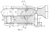
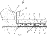
На фиг.1 изображены устройства для укладки пленочной завесы, установленные в единый ряд в шахматном порядке (продольный разрез); на фиг.2 - вид А-А на фиг.1; на фиг.3 - разрез Б-Б на фиг.2; на фиг.4 - узел В на фиг.1; на фиг.5 - узел Г на фиг.1.Figure 1 shows a device for laying a film curtain, installed in a single row in a checkerboard pattern (longitudinal section); figure 2 is a view aa in figure 1; figure 3 is a section bB in figure 2; figure 4 - node In figure 1; figure 5 - node G in figure 1.
Устройство содержит грузовую камеру 1 с крышкой 2, пленкой 3, скрученной в виде рулона, и тормозной планкой 4, направляющую камеру, состоящую из верхней выпуклой по отношению к бегущей пленке стенки, которая имеет криволинейную сужающуюся и прямолинейную части 5, 6, сопрягающиеся по линии 7, и противоположной, нижней стенки 8 (фиг.1, 2). Стенки направляющей камеры и нижней стенки сопряжены с плоскими отгибами 9 по округлым поверхностям 10 (фиг.3). На верхней стенке направляющей камеры прикреплены наклонные пластины 11 из твердого материала, например металла, а на нижней стенке 8 с уступом - ленты 12 из ворсового материала (фиг.4). Ворс лент 12 подстрижен так, что они, как и пластины 11, имеют наклонную фронтальную поверхность скольжения. При этом в статичном положении устройства ворс лент 12 в своей верхней части прижимает пленку в направляющей камере к верхней стенке (пунктирные линии на фиг.4). Отгибы 9 направляющей камеры заканчиваются плоскими прижимными пружинами 13. В стенках хвостовой части направляющей камеры выполнен вырез 14, над которым установлен бункер 15 для сыпучего грунта, например песчаного. Бункер состоит из передней стенки 16, соприкасающейся с прямой частью 6 направляющей камеры, и задней овальной стенки 17. К передней стенке 16 с наружной стороны прикреплен вибратор 18, а с внутренней - устройство 19, сигнализирующее о минимальном заполнения бункера грунтом (фиг.1, 4). К задней стенке бункера прикреплен сосуд 20 с клеящим веществом, заканчивающийся трубкой 21 с продольным щелевым отверстием 22 (фиг.5). Трубка 21 заведена между отгибами сопряженных полотнищ пленки, обжатых с одной стороны плоской прижимной пружиной 13, а с другой - грунтом. Прижимная пружина 13 контактирует через отгиб пленки с трубкой 21 по округлой поверхности. В статичном состоянии трубка 21 перекрыта клапаном 23. На наружной поверхности нижней стенки 8 прикреплены полозья скольжения 24 (фиг.1, 3, 4).The device comprises a cargo chamber 1 with a
Устройство для укладки противофильтрационной пленочной завесы с углом наклона к горизонту α≤90° работает следующим образом.A device for laying an impervious film curtain with an angle of inclination to the horizon α≤90 ° works as follows.
Устройства устанавливаются один к одному в два ряда, в шахматном порядке: передние - Ia, Iб, задние - II, на предварительно подготовленную поверхность (фиг.1, 2). Загружают все устройства рулонами пленки 3. Для этого открывают крышку 2 грузовой камеры 1, снимают криволинейную и прямолинейную части 5, 6 верхней стенки направляющей камеры. Загружают грузовую камеру рулоном пленки 3, протягивают пленку через направляющую камеру, загибая края пленки в отгибы 9, и протаскивают под бункером 15. Затем прикрепляют последовательно части 5 и 6 верхней стенки к отгибам нижней стенки 8. При этом пленка прижимается ворсовыми лентами 12 к верхней стенке и тем самым фиксируется в направляющей камере и ее отгибах. В бункеры 15 засыпают сыпучий грунт, который сразу просыпается на ранее вытянутую пленку 3 в пределах выреза 14 нижней стенки направляющей камеры и прижимает эту пленку к поверхности грунта (фиг.2, 4, 5). Сосуды 20 устройств, находящихся во II-ом ряду, заполняют клеящей жидкостью. Трубки сосудов 20 перекрыты клапанами 23.The devices are installed one to one in two rows, in a checkerboard pattern: front - Ia, Ib, rear - II, on a pre-prepared surface (figure 1, 2). Download all devices with rolls of
После загрузки устройств их начинают перемещать. Сначала перемещают выдвинутые вперед устройства Ia и Iб, а затем устройства II (на фиг.1 и 2 устройство Ia находится в состоянии перемещения, а Iб - в исходном состоянии). Защемленная грунтом пленка 3 сматывается с рулона и, проходя направляющую камеру, принимает U-образный профиль с отгибами, направленными вверх, то есть навстречу будущему фильтрационному потоку. Принятию такой формы способствует криволинейно-выпуклый по отношению к набегающей пленке сужающийся участок 5 верхней стенки направляющей камеры, симметрично расходящиеся наклонные пластины 11 и ворсовые ленты 12, а также сопряжения верхней и нижней стенок направляющей камеры с отгибами 9 по округлым поверхностям 10. Пленка, обтекая наклонные пластины и ленты 11, 12, оказывает на них усилие по всей их фронтальной поверхности соприкосновения с интенсивностью S (фиг.2), которое можно разложить на нормальную и касательную составляющие SN и ST. Усилие SN компенсируется реакцией пластин и лент 11, 12, а касательные усилия ST растягивают пленку в направлении от оси направляющей камеры к ее периферии в отгибы 9. При этом под действием пленки (с усилием SN) ворс лент 12 прогибается, и пленка при своем перемещении не касается верхней стенки направляющей камеры, а скользит по фронтальной поверхности ворсовых лент 12 и лент 11, растягиваясь в поперечном направлении в отгибы 9 направляющей камеры.After loading devices, they begin to move. First, the devices Ia and Ib are advanced, and then the devices II are moved (in FIGS. 1 and 2, the device Ia is in the moving state, and Ib is in the initial state). The
Вибратор 18 автоматически включается в работу при перемещении устройства. Под действием вибратора и сил гравитации сыпучий материал непрерывно высыпается на вытягиваемую пленку 3 (фиг.4, 5). Овальная форма стенок способствует быстрой эвакуации грунта из бункера. О необходимости загрузки новой порции грунта в бункер сигнализирует устройство 19.The
После перемещения устройств I-го ряда перемещают устройства II-го ряда. До момента, когда начинают перемещать очередное устройство из II-го ряда, открывается клапан в сосуде 20. Клеящее вещество заполняет трубку 21 и находится в ней до начала перемещения устройства, так как продольные отверстия 22 с обеих сторон плотно обжаты отгибами пленок устройств I-го и II-го рядов с помощью плоских пружин 13 с одной стороны и грунтом - с другой. При перемещении устройства клеящее вещество через продольные щелевые отверстия 22 тонким слоем смазывает отгибы сопрягающихся пленок. Склеенные отгибы плотно обжимаются пружинами 13 и грунтом. В момент остановки устройства клапан автоматически закрывается, прекращая поступление клеящего вещества в трубку 21.After moving the devices of the 1st row, the devices of the 2nd row are moved. Until the next device starts moving from the 2nd row, the valve in the
Тормозная планка 4 находится в постоянном контакте с рулоном пленки 3 (фиг.1), гася силы инерции и не давая ему раскручиваться и разматывать при этом излишнее количество пленки. Кроме того, тормозная планка по мере срабатывания рулона постепенно приближается к его оси и в момент, когда в рулоне остается минимальное количество пленки, воздействует на специальное устройство (не показано), издающее звуковой сигнал и предупреждающее "упуск" пленки из устройства. При подаче сигнала прекращают перемещение устройства, открывают крышку 2 и к концу сработанного рулона известным способом (например, свариванием) прикрепляют новый рулон пленки, и устройство вновь включается в работу.The brake bar 4 is in constant contact with the roll of film 3 (Fig. 1), damping the inertia forces and preventing it from unwinding and unwinding with it an excessive amount of film. In addition, the brake bar gradually approaches its axis as the roll is triggered and at the moment when the minimum amount of film remains in the roll, it acts on a special device (not shown) that emits an audible signal and prevents the film from “missing” from the device. When the signal is applied, the device is stopped moving, the
Устройство можно применить и при укладке вертикальной пленочной завесы, при этом бункер 15, присоединенный к отгибам 9 направляющей камеры, снимается. Технология укладки вертикальной завесы с помощью данных устройств аналогична приведенной в прототипе. Сосуд 20 с клеящим веществом заполняется в надземной части устройств II-го ряда, а трубки 21 с продольными отверстиями 22 остаются на прежнем месте и соединяются с сосудом длинными трубками, пропущенными, например, через отгибы направляющей камеры.The device can also be used when laying a vertical film curtain, while the
Таким образом, вырез в хвостовой части направляющей камеры и бункер с сыпучим грунтом над ним позволяют укладывать пленочную завесу на горизонтальную или наклонную поверхность под слой грунта. За перемещенными устройствами под слоем грунта остается единая пленочная завеса, отдельные полотнища которой сопрягаются друг с другом с помощью склеенных отгибов. Причем качество укладки завесы может быть оперативно проверено, так как отгибы находятся под относительно небольшим слоем грунта. Съемность бункера обеспечивает использование устройства для укладки вертикальных или крутонаклоненных завес.Thus, the cutout in the rear of the guide chamber and the hopper with loose soil above it allow you to lay the film curtain on a horizontal or inclined surface under the soil layer. A single film curtain remains behind the displaced devices under the soil layer, the individual panels of which are mated with each other using glued bends. Moreover, the quality of the installation of the curtain can be quickly checked, since the bends are under a relatively small layer of soil. Removable hopper allows the use of a device for laying vertical or steeply inclined curtains.
Claims (1)
Priority Applications (1)
| Application Number | Priority Date | Filing Date | Title |
|---|---|---|---|
| RU2004122378/03A RU2264503C1 (en) | 2004-07-21 | 2004-07-21 | Device for laying watertight film curtain |
Applications Claiming Priority (1)
| Application Number | Priority Date | Filing Date | Title |
|---|---|---|---|
| RU2004122378/03A RU2264503C1 (en) | 2004-07-21 | 2004-07-21 | Device for laying watertight film curtain |
Publications (1)
| Publication Number | Publication Date |
|---|---|
| RU2264503C1 true RU2264503C1 (en) | 2005-11-20 |
Family
ID=35867205
Family Applications (1)
| Application Number | Title | Priority Date | Filing Date |
|---|---|---|---|
| RU2004122378/03A RU2264503C1 (en) | 2004-07-21 | 2004-07-21 | Device for laying watertight film curtain |
Country Status (1)
| Country | Link |
|---|---|
| RU (1) | RU2264503C1 (en) |
Citations (8)
| Publication number | Priority date | Publication date | Assignee | Title |
|---|---|---|---|---|
| US1803838A (en) * | 1929-10-11 | 1931-05-05 | Charles E Carpenter | Eradication of quack grass and the like |
| SU681146A1 (en) * | 1977-06-15 | 1979-08-25 | Всесоюзный Научно-Исследовательский Институт Гидротехники Им. Б.Е.Веденеева | Device for producing antiseepage curtain |
| SU718531A1 (en) * | 1978-05-30 | 1980-02-29 | Украинский Научно-Исследовательский Институт Гидротехники И Мелиорации | Apparatus for forming antifiltration curtain |
| SU1161628A1 (en) * | 1983-12-13 | 1985-06-15 | Научно-исследовательский институт строительного производства Госстроя УССР | Arrangement for assembling and placing into soil vertical film screen |
| US4786208A (en) * | 1985-05-06 | 1988-11-22 | Solmat Systems Ltd. | Method of and apparatus for controlling fluid leakage through soil |
| SU1710654A1 (en) * | 1990-05-03 | 1992-02-07 | Сибирский филиал Всесоюзного научно-исследовательского института гидротехники им.Б.Е.Веденеева | Device for making film diaphragm in waterproof earth structure |
| RU2195528C2 (en) * | 2000-04-04 | 2002-12-27 | Красноярский государственный технический университет | Gear to lay antifiltration film curtain |
| RU2203357C2 (en) * | 2001-03-06 | 2003-04-27 | Красноярский государственный технический университет | Facility to form multiformation film diaphragm in backwater ground structure |
-
2004
- 2004-07-21 RU RU2004122378/03A patent/RU2264503C1/en not_active IP Right Cessation
Patent Citations (8)
| Publication number | Priority date | Publication date | Assignee | Title |
|---|---|---|---|---|
| US1803838A (en) * | 1929-10-11 | 1931-05-05 | Charles E Carpenter | Eradication of quack grass and the like |
| SU681146A1 (en) * | 1977-06-15 | 1979-08-25 | Всесоюзный Научно-Исследовательский Институт Гидротехники Им. Б.Е.Веденеева | Device for producing antiseepage curtain |
| SU718531A1 (en) * | 1978-05-30 | 1980-02-29 | Украинский Научно-Исследовательский Институт Гидротехники И Мелиорации | Apparatus for forming antifiltration curtain |
| SU1161628A1 (en) * | 1983-12-13 | 1985-06-15 | Научно-исследовательский институт строительного производства Госстроя УССР | Arrangement for assembling and placing into soil vertical film screen |
| US4786208A (en) * | 1985-05-06 | 1988-11-22 | Solmat Systems Ltd. | Method of and apparatus for controlling fluid leakage through soil |
| SU1710654A1 (en) * | 1990-05-03 | 1992-02-07 | Сибирский филиал Всесоюзного научно-исследовательского института гидротехники им.Б.Е.Веденеева | Device for making film diaphragm in waterproof earth structure |
| RU2195528C2 (en) * | 2000-04-04 | 2002-12-27 | Красноярский государственный технический университет | Gear to lay antifiltration film curtain |
| RU2203357C2 (en) * | 2001-03-06 | 2003-04-27 | Красноярский государственный технический университет | Facility to form multiformation film diaphragm in backwater ground structure |
Similar Documents
| Publication | Publication Date | Title |
|---|---|---|
| US5669732A (en) | Self-closing interlocking sandbags and process for erecting dams therefrom | |
| SK53198A3 (en) | Cell confinement structure | |
| KR930001425B1 (en) | Controlling erosion of river or sea beds | |
| FR2657370A1 (en) | METHOD AND ELEMENT FOR PRODUCING STRUCTURES FOR CONTAINING SOIL SURFACES | |
| CA2551938C (en) | Stabilized soil structure and facing elements for its construction | |
| CA2047177C (en) | Underwater soil retention structures | |
| EP0091531B1 (en) | Method and apparatus for placing a cover on an underwater structure or on an underwater land strip | |
| RU2264503C1 (en) | Device for laying watertight film curtain | |
| FR2685023A1 (en) | PIPE COATING PIPE IN A TRENCH. | |
| HUP0004933A2 (en) | Reinforced soil structure | |
| RU2203357C2 (en) | Facility to form multiformation film diaphragm in backwater ground structure | |
| JPH03233021A (en) | Method and unit for forming banking slope | |
| US11535996B2 (en) | Flood barriers | |
| NL1002981C2 (en) | Method of implementation and device for applying a fleece for the purpose of a channel sealing. | |
| SU1638419A1 (en) | A method for laying underground piping | |
| RU2195528C2 (en) | Gear to lay antifiltration film curtain | |
| DE19804662A1 (en) | System for securing and strengthening of dikes against the action of water and mechanical loads | |
| NL9500023A (en) | Emergency flood defense. | |
| SU1710654A1 (en) | Device for making film diaphragm in waterproof earth structure | |
| DE10111905B4 (en) | Water rampart | |
| JPS5898526A (en) | Concrete placing method for concrete mat | |
| FR2656885A1 (en) | Improved coating for protecting soil subject to erosion, and implementation method | |
| FR2602300A1 (en) | RECOVERY STRUCTURE INTENDED IN PARTICULAR TO BE INSTALLED ON A DRIVE OR THE LIKE SUBJECT TO THE SUB-MARINE BOTTOM | |
| SU681146A1 (en) | Device for producing antiseepage curtain | |
| KR0123814B1 (en) | Underwater soil conservation structures |
Legal Events
| Date | Code | Title | Description |
|---|---|---|---|
| MM4A | The patent is invalid due to non-payment of fees |
Effective date: 20060722 |