RU2256503C1 - Grinding apparatus - Google Patents
Grinding apparatus Download PDFInfo
- Publication number
- RU2256503C1 RU2256503C1 RU2003133108/03A RU2003133108A RU2256503C1 RU 2256503 C1 RU2256503 C1 RU 2256503C1 RU 2003133108/03 A RU2003133108/03 A RU 2003133108/03A RU 2003133108 A RU2003133108 A RU 2003133108A RU 2256503 C1 RU2256503 C1 RU 2256503C1
- Authority
- RU
- Russia
- Prior art keywords
- disks
- grinding
- crushing chamber
- hydraulic
- rotors
- Prior art date
Links
Images
Landscapes
- Crushing And Pulverization Processes (AREA)
- Crushing And Grinding (AREA)
Abstract
Description
Изобретение относится к области дробления, измельчения и/или смешивания различных материалов, в частности к мельницам с горизонтальной осью.The invention relates to the field of crushing, grinding and / or mixing of various materials, in particular to mills with a horizontal axis.
Известно устройство для измельчения, содержащее корпус с камерой дробления, средство подачи измельчаемого материала в камеру дробления, установленную в камере дробления пару роторов, каждый из которых выполнен с закрепленным на валу набором смежных дисков, имеющих разделительные элементы, и сопряженные с дисками съемники и гребенку (SU №351577, кл. В 02 С 7/02, 1972 г.).A grinding device is known, comprising a housing with a crushing chamber, means for feeding the crushed material into the crushing chamber, a pair of rotors installed in the crushing chamber, each of which is made with a set of adjacent disks having spacer elements fixed to the shaft and pullers and comb associated with the disks ( SU No. 351577, class B 02
Недостатком известного устройства, является сравнительно малая надежность вследствие неравномерного распределения измельчаемого материала в пространстве между дисками и возможности заклинивания роторов с остановкой процесса.A disadvantage of the known device is the relatively low reliability due to the uneven distribution of the crushed material in the space between the disks and the possibility of jamming of the rotors with stopping the process.
Более совершенным и наиболее близким аналогом заявляемому изобретению является устройство для измельчения, содержащее корпус с камерой дробления, средство подачи измельчаемого материала в камеру дробления, установленную в камере дробления пару роторов, каждый из которых выполнен с закрепленными на валу набором дисков и разделительных элементов между дисками, и сопряженные с дисками съемники и гребенку (RU №2126298, В 02 С 19/18, 1999 г.).A more perfect and closest analogue of the claimed invention is a grinding device comprising a housing with a crushing chamber, means for feeding the crushed material into the crushing chamber, a pair of rotors installed in the crushing chamber, each of which is made with a set of disks and separation elements between the disks fixed to the shaft, and strippers and a comb associated with discs (RU No. 2126298, B 02
В указанном устройстве надежность процесса измельчения повышена за счет выполнения кромки дисков с волнистой режущей кромкой. Однако такое техническое решение существенно ограничивает размеры зоны измельчения областью сопряжения режущих кромок, что в конечном итоге ограничивает возможную производительность устройства.In the specified device, the reliability of the grinding process is increased due to the implementation of the edges of the disks with a wavy cutting edge. However, this technical solution significantly limits the size of the grinding zone to the mating region of the cutting edges, which ultimately limits the possible performance of the device.
Задачей, на решение которой направлено заявляемое изобретение, является создание надежного и эффективного средства для измельчения.The problem to which the invention is directed, is the creation of a reliable and effective means for grinding.
Технический результат, который может быть получен при осуществлении изобретения, заключается в повышении производительности процесса измельчения за счет увеличения зоны измельчения и повышения эффективности посредством активации кавитационных процессов.The technical result that can be obtained by carrying out the invention is to increase the productivity of the grinding process by increasing the grinding zone and increasing efficiency by activating cavitation processes.
Указанный технический результат достигается устройством для измельчения, содержащим корпус с камерой дробления, средство подачи измельчаемого материала в камеру дробления, установленную в камере дробления пару роторов, каждый из которых выполнен с закрепленными на валу набором дисков и разделительных элементов между дисками, и сопряженные с дисками съемники и гребенку, за счет того, что средство подачи измельчаемого материала в камеру дробления выполнено в виде средства гидравлического нагнетания смеси жидкости с измельчаемым материалом, имеющего вводные штуцеры, при этом роторы выполнены с осевым нагнетательным каналом в валах и нагнетательными выводами в проемы между дисками, а вводные штуцеры установлены в осевых нагнетательных каналах и выполнены с выводами на внешнюю поверхность, с возможностью обеспечения дискретной гидравлической связи с нагнетательными выводами в проемы между дисками.The specified technical result is achieved by the grinding device, comprising a housing with a crushing chamber, means for feeding the crushed material into the crushing chamber, a pair of rotors installed in the crushing chamber, each of which is made with a set of disks and separation elements between the disks fixed to the shaft, and strippers associated with the disks and comb, due to the fact that the means for feeding the crushed material into the crushing chamber is made in the form of means for hydraulic pumping a mixture of liquid with the crushed material scrap with inlet fittings, the rotors are made with an axial discharge channel in the shafts and discharge leads into the openings between the disks, and the inlet fittings are installed in the axial discharge channels and are made with leads to the outer surface, with the possibility of providing discrete hydraulic communication with the discharge leads in openings between the disks.
А также за счет того, что средство гидравлического нагнетания измельчаемого материала выполнено с возможностью рециркуляции из камеры измельчения смеси жидкости с измельчаемым материалом.And also due to the fact that the means of hydraulic injection of the crushed material is made with the possibility of recirculation from the grinding chamber of the mixture of liquid with the crushed material.
А также за счет того, что средство гидравлического нагнетания измельчаемого материала выполнено с нагнетательным насосом и с буферной емкостью, имеющей гидравлические связи с камерой дробления, с нагнетательным насосом и со сливом.And also due to the fact that the means of hydraulic injection of the crushed material is made with a discharge pump and with a buffer tank having hydraulic connections with the crushing chamber, with a discharge pump and with a drain.
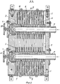
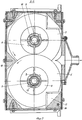
Сущность заявляемого изобретения поясняется чертежами, где на фиг.1 показана схема устройства, на фиг.2 - разрез А-А фиг.1, на фиг.3 - разрез Б-Б фиг.2.The essence of the invention is illustrated by drawings, where in Fig.1 shows a diagram of the device, Fig.2 is a section aa of Fig.1, Fig.3 is a section bB of Fig.2.
Устройство для измельчения содержит корпус 1 с камерой 2 дробления, внутри которой установлена пара роторов 3 с закрепленными на валу 4 набором дисков 5 и разделительных элементов 6 между дисками 5. Роторы 3 выполнены с осевым нагнетательным каналом 7 в валах 4 и нагнетательными выводами 8 в проемы между дисками 5, расположенными в разделительных элементах 6. В осевых нагнетательных каналах 7 установлены выводные штуцеры 9 средства подачи измельчаемого материала в камеру 2 дробления, выполненного в виде средства гидравлического нагнетания смеси жидкости с измельчаемым материалом. Вводные штуцеры 9 закреплены неподвижно и выполнены с выводами 10 на внешнюю поверхность, что обеспечивает возможность дискретной гидравлической связи с нагнетательными выводами 8 в проемы между дисками 5 в процессе вращения валов 4.The grinding device comprises a housing 1 with a
Средство подачи измельчаемого материала в камеру дробления выполнено в виде средства гидравлического нагнетания смеси жидкости с измельчаемым материалом с возможностью рециркуляции из камеры измельчения смеси жидкости с измельчаемым материалом и образовано нагнетательным насосом 11 (центробежный или вихревой) и буферной емкостью 12, имеющей гидравлические связи с камерой дробления посредством линии 13, с нагнетательным насосом 11 посредством линии 14 и со сливом посредством линии 15. Нагнетательный насос 11 в свою очередь гидравлически связан линией 16 с вводными штуцерами 9.The means for feeding the crushed material into the crushing chamber is made in the form of means for hydraulic injection of a liquid mixture with crushed material with the possibility of recirculation from the crushing chamber of a mixture of liquid with crushed material and is formed by a discharge pump 11 (centrifugal or vortex) and a buffer tank 12 having hydraulic connections with the crushing chamber through line 13, with a discharge pump 11 through line 14 and with a drain through line 15. The discharge pump 11, in turn, hydraulically line 16 coupled with the opening 9 fittings.
В камере дробления в промежутки между дисками 5 введены сопряженные с дисками 5 элементами 17 съемники 18 и гребенка 19. Валы 4 вращаются внешним приводом (на черт. не показан) с помощью муфт 20, причем направление вращения может быть как одинаковым, так и противоположным в зависимости от степени измельчения материала и его характеристик.In the crushing chamber, in between the
Устройство работает следующим образом.The device operates as follows.
Через заливную горловину 21 измельчаемый материал вместе с водой загружается в буферную емкость 12, откуда по линии 14 попадает в нагнетательный насос 11 и далее по линии 16 в выводные штуцеры 9. В момент, когда выводы 10 совпадают с нагнетательными выводами 8 при вращении вала 4, смесь измельчаемого материала с водой под действием давления и центробежных сил равномерно заполняет промежутки между дисками 5, где в результате столкновения частиц измельчаемого материала, истирания их смежными дисками 5 разных роторов 3 и гидродинамического воздействия гидроудара и кавитации происходит дробление до требуемого размера и одновременное смешивание. Смесь измельчаемого материала с водой удаляется из камеры 2 дробления по линии 13 за счет взаимодействия дисков 5 с элементами 17 гребенки 19 и съемников 18. Смесь измельчаемого материала с водой и частично может направляться обратно в камеру 2 по линии 14 для повторного измельчения.Through the filler neck 21, the crushed material together with water is loaded into the buffer tank 12, from where it enters the discharge pump 11 via line 14 and then to the
Claims (3)
Priority Applications (1)
| Application Number | Priority Date | Filing Date | Title |
|---|---|---|---|
| RU2003133108/03A RU2256503C1 (en) | 2003-11-12 | 2003-11-12 | Grinding apparatus |
Applications Claiming Priority (1)
| Application Number | Priority Date | Filing Date | Title |
|---|---|---|---|
| RU2003133108/03A RU2256503C1 (en) | 2003-11-12 | 2003-11-12 | Grinding apparatus |
Publications (2)
| Publication Number | Publication Date |
|---|---|
| RU2003133108A RU2003133108A (en) | 2005-04-20 |
| RU2256503C1 true RU2256503C1 (en) | 2005-07-20 |
Family
ID=35634635
Family Applications (1)
| Application Number | Title | Priority Date | Filing Date |
|---|---|---|---|
| RU2003133108/03A RU2256503C1 (en) | 2003-11-12 | 2003-11-12 | Grinding apparatus |
Country Status (1)
| Country | Link |
|---|---|
| RU (1) | RU2256503C1 (en) |
Cited By (1)
| Publication number | Priority date | Publication date | Assignee | Title |
|---|---|---|---|---|
| WO2009126058A1 (en) * | 2008-04-11 | 2009-10-15 | Shapovalov Viacheslav Dmitriev | Method for processing mineral and technogenic raw materials and a device for carrying out said method |
Citations (7)
| Publication number | Priority date | Publication date | Assignee | Title |
|---|---|---|---|---|
| GB1098546A (en) * | 1964-10-02 | 1968-01-10 | Norwood Henry Andrews | Improvements in jet pulveriser mills |
| FR2321332A1 (en) * | 1975-08-18 | 1977-03-18 | Micro Macinazione Sa | Centrifugal grinding machine using tangential pressure jets - has replaceable jets to vary angle of discharge into grinding chamber |
| US4056233A (en) * | 1976-10-01 | 1977-11-01 | Fay Edwin F | Apparatus for pulverizing solid materials |
| RU2016643C1 (en) * | 1991-03-14 | 1994-07-30 | Сергеев Геннадий Александрович | Disperser |
| RU2108160C1 (en) * | 1996-10-30 | 1998-04-10 | Стандарт-90 (Кипрус) Лимитед К/О Иксл. | Method and device for grinding materials |
| RU2126298C1 (en) * | 1996-09-05 | 1999-02-20 | Закрытое акционерное общество "Колинпласт Лтд." | Crusher |
| DE19824062A1 (en) * | 1998-05-29 | 1999-12-02 | Roland Nied | Grinding process using a jet mill |
-
2003
- 2003-11-12 RU RU2003133108/03A patent/RU2256503C1/en not_active IP Right Cessation
Patent Citations (7)
| Publication number | Priority date | Publication date | Assignee | Title |
|---|---|---|---|---|
| GB1098546A (en) * | 1964-10-02 | 1968-01-10 | Norwood Henry Andrews | Improvements in jet pulveriser mills |
| FR2321332A1 (en) * | 1975-08-18 | 1977-03-18 | Micro Macinazione Sa | Centrifugal grinding machine using tangential pressure jets - has replaceable jets to vary angle of discharge into grinding chamber |
| US4056233A (en) * | 1976-10-01 | 1977-11-01 | Fay Edwin F | Apparatus for pulverizing solid materials |
| RU2016643C1 (en) * | 1991-03-14 | 1994-07-30 | Сергеев Геннадий Александрович | Disperser |
| RU2126298C1 (en) * | 1996-09-05 | 1999-02-20 | Закрытое акционерное общество "Колинпласт Лтд." | Crusher |
| RU2108160C1 (en) * | 1996-10-30 | 1998-04-10 | Стандарт-90 (Кипрус) Лимитед К/О Иксл. | Method and device for grinding materials |
| DE19824062A1 (en) * | 1998-05-29 | 1999-12-02 | Roland Nied | Grinding process using a jet mill |
Cited By (1)
| Publication number | Priority date | Publication date | Assignee | Title |
|---|---|---|---|---|
| WO2009126058A1 (en) * | 2008-04-11 | 2009-10-15 | Shapovalov Viacheslav Dmitriev | Method for processing mineral and technogenic raw materials and a device for carrying out said method |
Also Published As
| Publication number | Publication date |
|---|---|
| RU2003133108A (en) | 2005-04-20 |
Similar Documents
| Publication | Publication Date | Title |
|---|---|---|
| RU2138334C1 (en) | Mill-mixer | |
| US4024168A (en) | Method of extracting oils from fruits such as seeds nuts and beans | |
| US3290016A (en) | Mixer means and impeller therefor | |
| US3533567A (en) | Apparatus for simultaneous oscillatory treatment of substances or mixtures thereof | |
| RU2185244C2 (en) | Method of production of liquid composite fuel; disintegrator and hydraulic impact-action unit for method embodiment | |
| RU2256503C1 (en) | Grinding apparatus | |
| JP2016028811A (en) | Equipment for preparing substances | |
| US3508651A (en) | Method and apparatus for screening pulp | |
| KR101307824B1 (en) | Grain peeling machine | |
| US2654294A (en) | Pulp shredding and treating machine | |
| CN206731217U (en) | A kind of Chinese medicine multi-stage crushing lapping device | |
| US1764020A (en) | Rotary cutting, mixing, and attrition mill | |
| RU2446015C1 (en) | Fibrous material grinder | |
| RU2204437C1 (en) | Rotary centrifugal grinder | |
| RU2158629C1 (en) | Rotary dispersing apparatus | |
| JPS6229554B2 (en) | ||
| GB1577794A (en) | Lump breaker apparatus for reactor tank | |
| RU2369439C1 (en) | Grinder-extractor | |
| US3241775A (en) | Apparatus and method for reducing the size of particles | |
| US4455092A (en) | Mixing apparatus | |
| RU2157732C2 (en) | Crusher-mixer | |
| RU2091455C1 (en) | Countercurrent extractor for grape refuse | |
| CN217190019U (en) | High-efficient breaker of coal | |
| CN215197350U (en) | Grinding device for treating acute upper gastrointestinal hemorrhage drugs | |
| US2609744A (en) | Press construction |
Legal Events
| Date | Code | Title | Description |
|---|---|---|---|
| MM4A | The patent is invalid due to non-payment of fees |
Effective date: 20071113 |
|
| NF4A | Reinstatement of patent |
Effective date: 20100610 |
|
| MM4A | The patent is invalid due to non-payment of fees |
Effective date: 20111113 |