RU2247309C1 - Rocket - Google Patents
Rocket Download PDFInfo
- Publication number
- RU2247309C1 RU2247309C1 RU2003118470/02A RU2003118470A RU2247309C1 RU 2247309 C1 RU2247309 C1 RU 2247309C1 RU 2003118470/02 A RU2003118470/02 A RU 2003118470/02A RU 2003118470 A RU2003118470 A RU 2003118470A RU 2247309 C1 RU2247309 C1 RU 2247309C1
- Authority
- RU
- Russia
- Prior art keywords
- projectile
- engine
- section
- rocket
- barrel
- Prior art date
Links
- 230000007423 decrease Effects 0.000 claims description 4
- 239000003380 propellant Substances 0.000 abstract description 15
- 230000000694 effects Effects 0.000 abstract description 2
- 238000009434 installation Methods 0.000 abstract 2
- 239000000126 substance Substances 0.000 abstract 1
- 238000000926 separation method Methods 0.000 description 18
- 239000007789 gas Substances 0.000 description 6
- 238000002485 combustion reaction Methods 0.000 description 5
- 238000000034 method Methods 0.000 description 4
- 244000309464 bull Species 0.000 description 2
- 230000003993 interaction Effects 0.000 description 2
- 238000010586 diagram Methods 0.000 description 1
- 230000035945 sensitivity Effects 0.000 description 1
Images
Landscapes
- Aiming, Guidance, Guns With A Light Source, Armor, Camouflage, And Targets (AREA)
Abstract
Description
Изобретение относится к области ракетной техники и может быть использовано в малогабаритных ракетных комплексах.The invention relates to the field of rocket technology and can be used in small-sized missile systems.
Известна ракета [1], принятая авторами за аналог, содержащая отделяемый стартовый двигатель, телескопически соединенный с кормовой частью маршевой ступени, калибр которой меньше калибра двигателя, посредством цилиндрического посадочного гнезда на переднем торце двигателя. Конструкция аналога обеспечивает сокращение длины снаряда. Разделение маршевой ступени и двигателя происходит после окончания работы двигателя за счет разности аэродинамических сил, действующих на маршевую ступень и корпус двигателя.Known rocket [1], adopted by the authors as an analogue, containing a detachable starting engine, telescopically connected to the aft of the march stage, the caliber of which is less than the caliber of the engine, by means of a cylindrical landing socket on the front end of the engine. The design of the analog provides a reduction in the length of the projectile. The separation of the sustainer stage and the engine occurs after the end of the engine due to the difference in aerodynamic forces acting on the sustainer stage and the engine housing.
Недостаток конструкции аналога заключается в том, что при разделении за счет разности аэродинамических сил относительная скорость маршевой ступени и двигателя невелика. При наличии боковых сил в момент отделения двигателя импульс боковой возмущающей силы прямо пропорционален времени ее действия, а время взаимодействия маршевой ступени и двигателя в этом случае значительное. В управляемом полете при наличии угла атаки это может привести к большим возмущениям маршевой ступени. В результате в момент разделения маршевая ступень может выйти из поля зрения луча системы управления.The disadvantage of the design of the analogue is that when separated due to the difference in aerodynamic forces, the relative speed of the mid-flight stage and the engine is small. If there are lateral forces at the time of engine separation, the impulse of the lateral disturbing force is directly proportional to the time of its action, and the interaction time of the mid-stage and the engine in this case is significant. In a controlled flight in the presence of an angle of attack, this can lead to large disturbances of the march stage. As a result, at the moment of separation, the marching stage can leave the field of view of the beam of the control system.
Известна ракета [2], конструкция которой является наиболее близким техническим решением к предлагаемому изобретению и принятая авторами в качестве прототипа. Она содержит двигатель, снабженный ствольной установкой, размещенной по ее продольной оси, в которой установлен метательный заряд и отделяемый снаряд, калибр которого меньше калибра двигателя. Отделение снаряда от двигателя осуществляется активным способом за счет сжигания метательного заряда, что значительно сокращает время взаимодействия двигателя и снаряда и обеспечивает малые возмущения в момент разделения за счет уменьшения импульса боковых сил.Known rocket [2], the design of which is the closest technical solution to the proposed invention and adopted by the authors as a prototype. It contains an engine equipped with a receiver mounted on its longitudinal axis, in which a propellant charge and detachable projectile are installed, the caliber of which is less than the caliber of the engine. The separation of the projectile from the engine is carried out in an active way by burning a propellant charge, which significantly reduces the time of interaction between the engine and the projectile and provides small disturbances at the time of separation due to a decrease in the lateral force momentum.
Однако при разделении активным способом в заснарядном объеме при сжигании метательного заряда создается высокое давление, при этом снаряд испытывает значительные продольные перегрузки, возрастающие от нуля до максимального значения в течение короткого времени, за которое сгорает метательный заряд. Все это ведет к тому, что для обеспечения прочности ствола и снаряда они должны иметь значительную массу, что ведет к росту пассивной массы всей ракеты.However, when the active method is separated in a projectile volume during the burning of the propellant, high pressure is created, while the projectile experiences significant longitudinal overloads, increasing from zero to the maximum value for a short time during which the propellant burns. All this leads to the fact that to ensure the strength of the barrel and the projectile they must have a significant mass, which leads to an increase in the passive mass of the entire rocket.
Задачей предлагаемого изобретения является снижение массы конструкции ракеты и уровня перегрузок, действующих на снаряд.The objective of the invention is to reduce the mass of the rocket design and the level of overloads acting on the projectile.
Техническое решение заключается в том, что в ракете, содержащей двигатель, снабженный ствольной установкой, размещенной внутри двигателя по его продольной оси, в которой установлен отделяемый на траектории снаряд, калибр которого меньше калибра двигателя и метательный заряд, метательный заряд размещен в полости, выполненной в задней части снаряда. Задняя часть наружной поверхности снаряда выполнена переменного сечения с обнижением в сторону заднего торца, при этом полость с метательным зарядом выполнена сообщающейся посредством газоводов с обниженной поверхностью снаряда. Выходы газоводов расположены симметрично по поперечному сечению корпуса снаряда, а донная часть ствольной установки сообщается с атмосферой посредством канала, площадь которого меньше площади поперечного сечения ствола.The technical solution consists in the fact that in a rocket containing an engine equipped with a receiver mounted inside the engine along its longitudinal axis, in which a projectile detachable on the trajectory is installed, the caliber of which is smaller than the caliber of the engine and the propellant charge, the propellant charge is placed in a cavity made in the back of the shell. The rear part of the outer surface of the projectile is made of variable cross section with a decrease towards the rear end, while the cavity with a propelling charge is made communicating by means of gas ducts with a reduced surface of the projectile. The outlets of the gas ducts are located symmetrically along the cross section of the shell of the projectile, and the bottom of the barrel mount communicates with the atmosphere through a channel whose area is less than the cross-sectional area of the barrel.
Такое решение позволяет производить процесс разделения активно-реактивным способом, что существенно снижает осевые перегрузки, действующие на снаряд, что позволяет в свою очередь снизить пассивную массу конструкции. Размещение заряда в полости отделяемого снаряда несколько увеличивает его массу и незначительно снижает скорость при разделении, но при этом значительно снижается давление в стволе, что позволяет уменьшить толщину его стенки и уменьшить тем самым его массу. При таком перераспределении массы уменьшаются потери кинетической энергии снаряда после отделения от него двигателя, благодаря чему может быть увеличена дальность полета снаряда.This solution allows the separation process to be carried out in an active-reactive manner, which significantly reduces the axial load acting on the projectile, which in turn reduces the passive mass of the structure. The placement of the charge in the cavity of the detachable projectile slightly increases its mass and slightly reduces the speed during separation, but at the same time the pressure in the barrel is significantly reduced, which allows to reduce the thickness of its wall and thereby reduce its mass. With this redistribution of mass, the loss of kinetic energy of the projectile after the engine is separated from it is reduced, so that the range of the projectile can be increased.
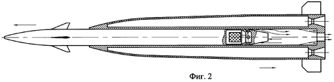
Сущность предлагаемого изобретения поясняется схемой ракеты перед разделением, представленной на фиг.1, и схемой процесса разделения снаряда и двигателя, представленной на фиг.2.The essence of the invention is illustrated by the scheme of the rocket before separation, shown in figure 1, and the process diagram of the separation of the projectile and engine, presented in figure 2.
Ракета (фиг.1) содержит двигатель 1 со ствольной установкой 2, в которой установлен отделяемый снаряд 3, калибр которого меньше калибра двигателя. Снаряд снабжен полостью 4, выполненной в его задней части, в которой размещен метательный заряд 5. Задняя часть снаряда А выполнена конической. Полость 4 с размещенным в ней метательным зарядом 5 сообщается посредством газоводов 6 с обниженной поверхностью снаряда 3, донная часть 7 ствольной установки сообщается с атмосферой посредством канала Б, площадь которого меньше площади поперечного сечения ствола.The rocket (figure 1) contains an engine 1 with a receiver 2, in which a detachable projectile 3 is installed, the caliber of which is less than the caliber of the engine. The projectile is equipped with a cavity 4 made in its rear part, in which the propellant charge 5 is placed. The rear part of the projectile A is conical. The cavity 4 with the propelling charge 5 placed in it communicates by means of gas ducts 6 with the reduced surface of the projectile 3, the bottom part 7 of the barrel mount communicates with the atmosphere through channel B, the area of which is less than the cross-sectional area of the barrel.
Устройство работает следующим образом.The device operates as follows.
В полете при работе двигателя 1 боковая стенка ствола 2 испытывает сжимающее усилие со стороны продуктов сгорания в камере двигателя, которое передается на корпус снаряда 3. Это позволяет частично разгрузить стенку ствола и обеспечить ее устойчивость при меньшей толщине. Отделение снаряда 3 происходит после окончания работы двигателя 1. При этом в момент спада тяги в конце работы двигателя, например, по сигналу инерционного замыкателя поджигается заряд 5, размещенный в полости 4 снаряда 3. Продукты сгорания заряда истекают через газоводы 6 на обниженную часть корпуса снаряда А, которая образует со стенками ствольной установки кольцевое реактивное сопло с внешним расширением (штыревое сопло). Продукты сгорания метательного заряда 5 при течении вдоль стенки ствола создают силу трения, увеличивающую скорость отделения двигателя. При истечении из заснарядного пространства в атмосферу через канал Б продукты сгорания метательного заряда, тормозясь перед входом в канал Б, площадь которого меньше площади поперечного сечения ствола, создают дополнительную силу, также увеличивающую скорость отделения двигателя. Симметричное размещение выходов газоводов практически полностью исключает боковое воздействие газов на снаряд после разделения в случае неполного сгорания метательного заряда.In flight, when the engine 1 is operating, the side wall of the barrel 2 experiences a compressive force from the side of the combustion products in the engine chamber, which is transmitted to the shell of the projectile 3. This allows the barrel wall to be partially unloaded and to ensure its stability with a smaller thickness. The separation of the projectile 3 occurs after the end of the operation of the engine 1. At the same time, at the end of the thrust at the end of the engine’s operation, for example, the charge 5 placed in the cavity 4 of the projectile 3 is ignited by the signal of the inertial contactor. The products of charge combustion expire through the gas ducts 6 to the lower part of the shell of the projectile A, which forms an annular jet nozzle with external expansion (pin nozzle) with the walls of the receiver. The combustion products of the propellant charge 5 during flow along the barrel wall create a friction force that increases the speed of engine separation. When the propellant combustion products expire from the casing space into the atmosphere through channel B, braking before entering the channel B, the area of which is less than the cross-sectional area of the barrel, creates additional force, which also increases the engine separation speed. The symmetrical arrangement of the gas outlet exits almost completely eliminates the lateral effect of gases on the projectile after separation in the case of incomplete combustion of the propellant charge.
Разгрузка корпуса ствольной установки на корпус снаряда и использование для разделения двигателя и снаряда принципа активно-реактивного метания позволяет существенно снизить вес ствольной установки, а следовательно, пассивный вес ракеты. Размещение полости с метательным зарядом внутри снаряда позволяет увеличить его инерционность, а следовательно, уменьшить чувствительность к боковым возмущениям при разделении, при этом кинетическая энергия снаряда после разделения уменьшается незначительно по сравнению с конструкцией, в которой метательный заряд размещен непосредственно в заснарядном пространстве (активный принцип метания).Unloading the barrel mount on the shell of the shell and using the principle of active-jet throwing to separate the engine and the shell allows you to significantly reduce the weight of the barrel mount, and therefore the passive weight of the rocket. Placing a cavity with a propellant charge inside the projectile allows it to increase its inertia and, consequently, reduce sensitivity to lateral disturbances during separation, while the kinetic energy of the projectile after separation decreases slightly compared to the design in which the propellant charge is placed directly in the projectile space (active throwing principle )
Таким образом, в предлагаемом техническом решении обеспечиваются минимальные возмущения снаряда в процессе отделения двигателя за счет использования активно-реактивной системы разделения при минимальной массе конструкции ракеты и уровне осевых перегрузок, действующих на снаряд в процессе отделения двигателя. Последнее обстоятельство благоприятно сказывается на функционировании гироскопических и инерциальных приборов управляемого снаряда.Thus, in the proposed technical solution, the minimum perturbations of the projectile in the process of engine separation are provided by using an active-reactive separation system with a minimum mass of the rocket structure and the level of axial overloads acting on the projectile in the process of engine separation. The latter circumstance favorably affects the functioning of gyroscopic and inertial devices of a guided projectile.
Источники информацииSources of information
1. Патент RU №2127418, опубликован 10.03.99 г., бюл. №7.1. Patent RU No. 2147418, published March 10, 1999, bull. Number 7.
2. Патент RU №2108537, опубликован 10.04.98 г., бюл. №10.2. Patent RU No. 2108537, published on 04/10/98, bull. No. 10.
Claims (1)
Priority Applications (1)
| Application Number | Priority Date | Filing Date | Title |
|---|---|---|---|
| RU2003118470/02A RU2247309C1 (en) | 2003-06-18 | 2003-06-18 | Rocket |
Applications Claiming Priority (1)
| Application Number | Priority Date | Filing Date | Title |
|---|---|---|---|
| RU2003118470/02A RU2247309C1 (en) | 2003-06-18 | 2003-06-18 | Rocket |
Publications (2)
| Publication Number | Publication Date |
|---|---|
| RU2003118470A RU2003118470A (en) | 2004-12-20 |
| RU2247309C1 true RU2247309C1 (en) | 2005-02-27 |
Family
ID=35286348
Family Applications (1)
| Application Number | Title | Priority Date | Filing Date |
|---|---|---|---|
| RU2003118470/02A RU2247309C1 (en) | 2003-06-18 | 2003-06-18 | Rocket |
Country Status (1)
| Country | Link |
|---|---|
| RU (1) | RU2247309C1 (en) |
Cited By (1)
| Publication number | Priority date | Publication date | Assignee | Title |
|---|---|---|---|---|
| RU2715009C1 (en) * | 2019-06-14 | 2020-02-21 | Акционерное общество "Конструкторское бюро приборостроения им. академика А.Г. Шипунова" | Two-stage banking missile |
Citations (7)
| Publication number | Priority date | Publication date | Assignee | Title |
|---|---|---|---|---|
| DE1800776A1 (en) * | 1968-10-03 | 1970-08-06 | Messerschmitt Boelkow Blohm | Recoil propelled missile |
| US3754507A (en) * | 1972-05-30 | 1973-08-28 | Us Navy | Penetrator projectile |
| GB1331046A (en) * | 1969-09-12 | 1973-09-19 | Bristol Aerojet Ltd | Rocket vehicles |
| EP0335761A1 (en) * | 1988-03-30 | 1989-10-04 | AEROSPATIALE Société Nationale Industrielle | Airborne vehicle with at least one releasable propulsion unit |
| US5005781A (en) * | 1989-03-27 | 1991-04-09 | Hughes Aircraft Company | In-flight reconfigurable missile construction |
| RU2108537C1 (en) * | 1994-04-19 | 1998-04-10 | Владимир Алексеевич Одинцов | Kinetic-action anti-tank missile |
| RU2127418C1 (en) * | 1998-03-25 | 1999-03-10 | Конструкторское бюро приборостроения | Bicaliber guided missile |
-
2003
- 2003-06-18 RU RU2003118470/02A patent/RU2247309C1/en active
Patent Citations (7)
| Publication number | Priority date | Publication date | Assignee | Title |
|---|---|---|---|---|
| DE1800776A1 (en) * | 1968-10-03 | 1970-08-06 | Messerschmitt Boelkow Blohm | Recoil propelled missile |
| GB1331046A (en) * | 1969-09-12 | 1973-09-19 | Bristol Aerojet Ltd | Rocket vehicles |
| US3754507A (en) * | 1972-05-30 | 1973-08-28 | Us Navy | Penetrator projectile |
| EP0335761A1 (en) * | 1988-03-30 | 1989-10-04 | AEROSPATIALE Société Nationale Industrielle | Airborne vehicle with at least one releasable propulsion unit |
| US5005781A (en) * | 1989-03-27 | 1991-04-09 | Hughes Aircraft Company | In-flight reconfigurable missile construction |
| RU2108537C1 (en) * | 1994-04-19 | 1998-04-10 | Владимир Алексеевич Одинцов | Kinetic-action anti-tank missile |
| RU2127418C1 (en) * | 1998-03-25 | 1999-03-10 | Конструкторское бюро приборостроения | Bicaliber guided missile |
Cited By (1)
| Publication number | Priority date | Publication date | Assignee | Title |
|---|---|---|---|---|
| RU2715009C1 (en) * | 2019-06-14 | 2020-02-21 | Акционерное общество "Конструкторское бюро приборостроения им. академика А.Г. Шипунова" | Two-stage banking missile |
Similar Documents
| Publication | Publication Date | Title |
|---|---|---|
| US5578783A (en) | RAM accelerator system and device | |
| RU2117907C1 (en) | Winged missile | |
| RU2135925C1 (en) | Boosting device | |
| US3167016A (en) | Rocket propelled missile | |
| US3749334A (en) | Attitude compensating missile system | |
| US4964339A (en) | Multiple stage rocket propelled missile system | |
| KR101494393B1 (en) | Dual thrust rocket propulsion machinery | |
| RU2247309C1 (en) | Rocket | |
| US5892217A (en) | Lock and slide mechanism for tube launched projectiles | |
| RU2175726C1 (en) | Solid-propellant engine boost unit | |
| RU2222771C1 (en) | Rocket | |
| US20140077024A1 (en) | Spin or Aerodynamically Stabilized Ammunition | |
| JP5829278B2 (en) | Propulsion systems for flying machines, especially missiles | |
| EP4232700B1 (en) | Integrated propulsion and warhead system for an artillery round | |
| RU2754475C1 (en) | Hypersonic rocket missile | |
| RU2422760C1 (en) | Bicalibre controlled missile | |
| RU2251070C2 (en) | Sub-caliber round | |
| RU2209331C2 (en) | Solid-propellant acceleration engine plant | |
| RU2233421C2 (en) | Radio-controlled projectile | |
| US10030951B2 (en) | Drag reduction system | |
| RU2386921C1 (en) | Multistage anti-aircraft missile and method of its tactical employment | |
| EP4354077A1 (en) | A solid fuel propelled projectile | |
| RU2247932C1 (en) | Method for launching of jet projectile and complex of armament for its realization | |
| RU2038570C1 (en) | Shell for smoothbore artillery systems | |
| RU2239778C1 (en) | Rocket |
Legal Events
| Date | Code | Title | Description |
|---|---|---|---|
| PC43 | Official registration of the transfer of the exclusive right without contract for inventions |
Effective date: 20190628 |