RU2238441C1 - Protection device for hydraulic protection of submersible oil-filled electric motor - Google Patents
Protection device for hydraulic protection of submersible oil-filled electric motor Download PDFInfo
- Publication number
- RU2238441C1 RU2238441C1 RU2003113187/06A RU2003113187A RU2238441C1 RU 2238441 C1 RU2238441 C1 RU 2238441C1 RU 2003113187/06 A RU2003113187/06 A RU 2003113187/06A RU 2003113187 A RU2003113187 A RU 2003113187A RU 2238441 C1 RU2238441 C1 RU 2238441C1
- Authority
- RU
- Russia
- Prior art keywords
- shaft
- electric motor
- rings
- pairs
- seal
- Prior art date
Links
Images
Abstract
Description
Изобретение относится к области машиностроения, в частности, к гидравлической защите погружных маслозаполненных электродвигателей от пластовой жидкости, предназначенных для привода погружных насосов для добычи нефти.The invention relates to the field of mechanical engineering, in particular, to hydraulic protection of submersible oil-filled electric motors from formation fluid, designed to drive submersible pumps for oil production.
Известно устройство для гидравлической защиты погружного маслозаполненного электродвигателя, содержащее вал с верхним и нижним торцовыми уплотнениями и корпус, герметично разделенный эластичной диафрагмой на заполненные маслом внутреннюю камеру и верхнюю камеру, разделенную ниппелем на верхнюю и нижнюю части (авторское свидетельство СССР №1767623, 1990).A device is known for hydraulic protection of a submersible oil-filled electric motor, comprising a shaft with upper and lower mechanical seals and a housing hermetically separated by an elastic diaphragm into an inner chamber and an upper chamber filled with oil, divided by a nipple into the upper and lower parts (USSR copyright certificate No. 1767623, 1990).
Недостатком известной конструкции является недостаточная герметичность от пластовой жидкости, проникающей в электродвигатель, что приводит к выходу его из строя.A disadvantage of the known design is the lack of tightness from the reservoir fluid penetrating into the electric motor, which leads to its failure.
Наиболее близким к изобретению является протектор для гидравлической защиты погружного маслозаполненого электродвигателя, содержащий корпус, вал с нижним и верхним торцовыми уплотнениями, упругую диафрагму, охватывающую вал в зоне под нижним торцовым уплотнением и закрепленную на опоре, первый и второй ниппели, между которыми размещен узел пяты, верхнюю и нижнюю головки с фланцами для соединения с насосом и электродвигателем, клапан, кожух, установленный посредством фланца на верхнем торцовом уплотнении, и отбойник, жестко закрепленный на валу выше верхнего торцового уплотнения (пат. РФ №2099604, 1997).Closest to the invention is a tread for hydraulic protection of a submersible oil-filled electric motor, comprising a housing, a shaft with lower and upper mechanical seals, an elastic diaphragm covering the shaft in the area under the lower mechanical seal and mounted on a support, the first and second nipples, between which the heel assembly is located , the upper and lower heads with flanges for connecting to the pump and electric motor, the valve, the casing mounted by means of a flange on the upper mechanical seal, and the chipper are rigidly fixed d on the shaft above the upper mechanical seal (US Pat. RF No. 2099604, 1997).
Недостатком известной конструкции является также недостаточная герметичность от пластовой жидкости полости электродвигателя, являющаяся причиной его отказа.A disadvantage of the known design is also the lack of tightness from the reservoir fluid of the cavity of the electric motor, which is the reason for its failure.
Задачей, на решение которой направлено настоящее изобретение, является создание конструкции протектора, обеспечивающей защиту электродвигателя от пластовой жидкости и повышение его долговечности.The problem to which the present invention is directed, is to create a tread structure that protects the motor from formation fluid and increase its durability.
Поставленная задача решается тем, что протектор для гидравлической защиты погружного маслозаполненного электродвигателя содержит корпус, вал с нижним и верхним торцовыми уплотнениями, упругую диафрагму, закрепленную на опорах и охватывающую вал в зоне под нижним торцовым уплотнением, первый и второй ниппели, между которыми размещен узел пяты, верхнюю и нижнюю головки с фланцами для соединения соответственно с насосом и электродвигателем, клапан, кожух, установленный посредством фланца на верхнем торцовом уплотнении, и отбойник, жестко закрепленный на валу выше верхнего торцового уплотнения, при этом протектор снабжен удлинителем вала и установленной на профилированной опоре дополнительной упругой диафрагмой, охватывающей герметично удлинитель вала в зоне над верхним торцовым уплотнением, отбойник выполнен в виде втулки, установленной на удлинителе вала над дополнительной упругой диафрагмой, при этом со стороны наружной поверхности втулки установлено радиальное уплотнение, выполненное в виде размещенного в верхней головке стакана, охватывающего втулку, с выполненными в стакане эксцентричными относительно друг друга кольцевыми канавками, в которых размещены насажанные на втулку кольца из антифрикционного материала и охватывающие их резиновые кольца с круглым поперечным сечением, причем соседние кольцевые канавки попарно смещены относительно друг друга на 0,2-0,5 мм в диаметрально противоположном направлении и указанные пары диаметрально смещенных относительно друг друга кольцевых канавок повернуты относительно соседних пар кольцевых канавок таким образом, что радиальные плоскости, проходящие через оси этих соседних пар канавок, повернуты относительно друг друга вокруг оси вала на угол, составляющий 360°/n, где n - число пар антифрикционных колец, причем число канавок четно и не менее 6, и в осевом направлении антифрикционные кольца прижаты друг к другу посредством подпружиненного кольца, а дополнительная упругая диафрагма установлена с образованием внутренней полости, сообщенной с окружающей средой через выпускной клапан для сброса воздуха, и со стороны наружной поверхности совместно с защитной обечайкой, опорой дополнительной упругой диафрагмы и стаканом уплотнения отбойника – полости, сообщенной с окружающей протектор средой.The problem is solved in that the tread for hydraulic protection of a submersible oil-filled electric motor contains a housing, a shaft with lower and upper mechanical seals, an elastic diaphragm mounted on bearings and covering the shaft in the area under the lower mechanical seal, the first and second nipples, between which the heel assembly is located , upper and lower heads with flanges for connection with a pump and an electric motor, a valve, a casing mounted by means of a flange on the upper mechanical seal, and a chipper, rigidly mounted on the shaft above the upper mechanical seal, the protector is equipped with a shaft extension and an additional elastic diaphragm mounted on a profiled support, covering the shaft extension in the area above the upper mechanical seal, the bump is made in the form of a sleeve mounted on the shaft extension over the additional elastic diaphragm, with this from the side of the outer surface of the sleeve installed radial seal, made in the form placed in the upper head of the glass covering the sleeve, with eccentric annular grooves relative to each other in a glass, in which rings of antifriction material mounted on the sleeve are placed and rubber rings with a circular cross-section cross over them, and adjacent annular grooves are pairwise offset from each other by 0.2-0.5 mm diametrically in the opposite direction and the indicated pairs of annular grooves diametrically offset from each other are rotated relative to adjacent pairs of annular grooves so that the radial planes passing e through the axes of these adjacent pairs of grooves, are rotated relative to each other around the axis of the shaft by an angle of 360 ° / n, where n is the number of pairs of antifriction rings, and the number of grooves is even and at least 6, and in the axial direction the antifriction rings are pressed against each other to a friend by means of a spring-loaded ring, and an additional elastic diaphragm is installed with the formation of an internal cavity in communication with the environment through an exhaust valve for venting air, and from the side of the outer surface together with a protective shell, support additionally th elastic diaphragm and a glass seal of the chipper - a cavity in communication with the environment surrounding the tread.
В результате такого радиального уплотнения наружной боковой поверхности отбойника обеспечивается высокая герметичность протектора и повышение долговечности погружного электродвигателя.As a result of such a radial seal on the outer side surface of the chipper provides a high tightness of the tread and increase the durability of the submersible motor.
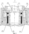
На фиг.1 представлен продольный разрез протектора для гидравлической защиты погружного электродвигателя, на фиг.2 представлено радиальное уплотнение втулки удлинителя вала по фиг.1.Figure 1 shows a longitudinal section of the tread for hydraulic protection of a submersible motor, figure 2 shows the radial seal of the sleeve of the shaft extension of figure 1.
Устройство содержит корпус 1, внутри которого размещена диафрагма 2, закрепленная на опоре 3, первый и второй ниппели 4 и 5, между которыми размещен узел пяты 6, верхнюю и нижнюю головки 7 и 8, вал 9 с верхним и нижним торцовыми уплотнениями 10 и 11 соответственно, клапан 12 с пробкой 13.The device comprises a housing 1, inside which a diaphragm 2 is mounted, mounted on a support 3, the first and second nipples 4 and 5, between which the heel assembly 6, the upper and lower heads 7 and 8, the shaft 9 with the upper and lower mechanical seals 10 and 11 are placed accordingly, valve 12 with plug 13.
Для удаления воздуха при заполнении маслом полостей протектора в ниппелях 4 и 5 имеются отверстия, которые герметично закрыты пробками 14 и 15.To remove air when filling the tread cavities with oil, nipples 4 and 5 have openings that are hermetically sealed with plugs 14 and 15.
Верхние и нижние головки 7 и 8 протектора имеют фланцы 16 и 17 для соединения соответственно с насосом и электродвигателем (на чертежах не показаны).The upper and lower tread heads 7 and 8 have flanges 16 and 17 for connection with a pump and an electric motor, respectively (not shown in the drawings).
Нижняя головка 8 имеет посадочный бурт с резиновыми кольцами для герметизации соединения с электродвигателем.The lower head 8 has a landing collar with rubber rings to seal the connection to the electric motor.
Нижний конец вала 9 соединяется с валом электродвигателя, а верхний конец посредством удлинителя 18 с валом 9 насоса при монтаже на скважине.The lower end of the shaft 9 is connected to the motor shaft, and the upper end by means of an
Кроме того, имеется кожух 19, установленный на верхнем торцовом уплотнении 10, и отбойник 20, выполненный в форме втулки и установленный жестко на удлинителе 18 вала 9 над кожухом 19. Вал 9 соединен с удлинителем 18 посредством шлицевой втулки 21.In addition, there is a casing 19 mounted on the upper mechanical seal 10, and a
Каждый ниппель 4 и 5 содержит отверстие 22 для удаления воздуха при заполнении маслом полости протектора.Each nipple 4 and 5 contains an opening 22 for removing air when filling the tread cavity with oil.
Для опоры вала 9 и его удлинителя 18 вала 9 служат подшипники скольжения 23.To support the shaft 9 and its
В верхней головке 7 в эксцентричных кольцевых канавках стакана 24 установлены резиновые кольца 25 круглого поперечного сечения, внутри которых размещены кольца 26 из антифрикционного материала, контактирующие с наружной боковой поверхностью отбойника 20 и подпружиненных в продольном направлении посредством кольца 27 и резинового кольца 28.In the upper head 7, in the eccentric annular grooves of the
Между головкой 7 и ниппелем 4 закреплена на опоре 29 дополнительная упругая диафрагма 30, внутренняя полость которой заполняется маслом через отверстие, закрытое пробкой 31, а сброс воздуха из ее полости осуществляется через выпускной клапан 32. При этом внутренняя полость над верхним торцевым уплотнением 10 не имеет связи со средой.Between the head 7 and the nipple 4, an additional elastic diaphragm 30 is fixed on the support 29, the internal cavity of which is filled with oil through an opening closed by the plug 31, and air is discharged from its cavity through the exhaust valve 32. In this case, the internal cavity above the upper mechanical seal 10 does not have communication with the environment.
Со стороны наружной поверхности дополнительная упругая диафрагма 30 совместно с защитной обечайкой 33, опорой 29 дополнительной упругой диафрагмы 30 и стаканом 24 радиального уплотнения отбойника 20 образует полость, сообщенную с окружающей протектор средой.On the outer surface side, the additional elastic diaphragm 30 together with the protective shell 33, the support 29 of the additional elastic diaphragm 30 and the
Работа устройства.The operation of the device.
Перед работой внутреннюю полость диафрагм 2 и 30 протектора заполняют маслом (например, типа МА-ПЭД) при монтаже двигателя. Это масло служит запасом для компенсации его естественного расхода через верхнее и нижнее торцевое уплотнение 10 и 11, герметизирующее вращающийся вал 9.Before work, the inner cavity of the diaphragms 2 and 30 of the tread is filled with oil (for example, type MA-PED) when mounting the engine. This oil serves as a reserve to compensate for its natural flow rate through the upper and lower mechanical seal 10 and 11, which seals the rotating shaft 9.
Полость за диафрагмой 2 сообщается с полостью узла пяты 6 и тоже заполняется маслом для компенсации расхода через верхнее торцевое уплотнение 10, расположенное ближе к верху протектора. По мере уменьшения количества масла в процессе работы устройства эта полость заполняется пластовой жидкостью через клапан 12, к которому жидкость поступает через отверстие в нижней головке 8, которое на время хранения и транспортировки закрыто пробкой 13.The cavity behind the diaphragm 2 communicates with the cavity of the heel assembly 6 and is also filled with oil to compensate for the flow through the upper mechanical seal 10 located closer to the top of the tread. As the amount of oil decreases during the operation of the device, this cavity is filled with formation fluid through a valve 12, to which the fluid enters through an opening in the lower head 8, which is closed by a stopper 13 during storage and transportation.
При этом обеспечивается выравнивание давлений в полостях протектора с давлением пластовой жидкости в зоне подвески двигателя.This ensures pressure equalization in the tread cavities with reservoir fluid pressure in the engine mount area.
Наличие уплотнения втулки-отбойника 20 не позволяет механическим примесям и воде непосредственно попадать на кожух 19 верхнего торцевого уплотнения 10, а наличие масла в полости дополнительной диафрагмы 30 повышает долговечность работы верхнего торцевого уплотнения 10 и герметичность протектора.The presence of the seal of the
Таким образом, вышеописанные изменения в конструкции протектора создают надежную защиту от воздействия механических частиц и пластовой жидкости, что значительно удлиняет срок службы устройства.Thus, the above changes in the design of the tread provide reliable protection against mechanical particles and formation fluid, which significantly lengthens the life of the device.
Claims (1)
Priority Applications (1)
| Application Number | Priority Date | Filing Date | Title |
|---|---|---|---|
| RU2003113187/06A RU2238441C1 (en) | 2003-05-07 | 2003-05-07 | Protection device for hydraulic protection of submersible oil-filled electric motor |
Applications Claiming Priority (1)
| Application Number | Priority Date | Filing Date | Title |
|---|---|---|---|
| RU2003113187/06A RU2238441C1 (en) | 2003-05-07 | 2003-05-07 | Protection device for hydraulic protection of submersible oil-filled electric motor |
Publications (2)
| Publication Number | Publication Date |
|---|---|
| RU2238441C1 true RU2238441C1 (en) | 2004-10-20 |
| RU2003113187A RU2003113187A (en) | 2004-11-10 |
Family
ID=33537958
Family Applications (1)
| Application Number | Title | Priority Date | Filing Date |
|---|---|---|---|
| RU2003113187/06A RU2238441C1 (en) | 2003-05-07 | 2003-05-07 | Protection device for hydraulic protection of submersible oil-filled electric motor |
Country Status (1)
| Country | Link |
|---|---|
| RU (1) | RU2238441C1 (en) |
Cited By (5)
| Publication number | Priority date | Publication date | Assignee | Title |
|---|---|---|---|---|
| RU2520128C1 (en) * | 2012-12-03 | 2014-06-20 | Общество с ограниченной ответственностью "Актуальные технологии нефтеотдачи" (ООО "АТН") | Protector for hydraulic protection of submerged oil-filled electromotor |
| RU2549381C1 (en) * | 2014-05-29 | 2015-04-27 | Валерий Алексеевич Калий | Borehole linear motor |
| RU2609899C1 (en) * | 2015-10-08 | 2017-02-07 | Закрытое акционерное общество "РИМЕРА" | Protection of hydraulic submersible motor gages (versions) |
| RU2659604C2 (en) * | 2013-12-20 | 2018-07-03 | ДжиИ ОЙЛ ЭНД ГЭС ЭСП, ИНК. | Electric submersible pumping systems protector design |
| RU2800766C1 (en) * | 2023-01-30 | 2023-07-28 | Акционерное общество "Новомет-Пермь" | Device for hydraulic protection of submersible oil-filled electric motor |
-
2003
- 2003-05-07 RU RU2003113187/06A patent/RU2238441C1/en not_active IP Right Cessation
Cited By (6)
| Publication number | Priority date | Publication date | Assignee | Title |
|---|---|---|---|---|
| RU2520128C1 (en) * | 2012-12-03 | 2014-06-20 | Общество с ограниченной ответственностью "Актуальные технологии нефтеотдачи" (ООО "АТН") | Protector for hydraulic protection of submerged oil-filled electromotor |
| RU2659604C2 (en) * | 2013-12-20 | 2018-07-03 | ДжиИ ОЙЛ ЭНД ГЭС ЭСП, ИНК. | Electric submersible pumping systems protector design |
| US10301915B2 (en) | 2013-12-20 | 2019-05-28 | Ge Oil & Gas Esp, Inc. | Seal configuration for ESP systems |
| RU2549381C1 (en) * | 2014-05-29 | 2015-04-27 | Валерий Алексеевич Калий | Borehole linear motor |
| RU2609899C1 (en) * | 2015-10-08 | 2017-02-07 | Закрытое акционерное общество "РИМЕРА" | Protection of hydraulic submersible motor gages (versions) |
| RU2800766C1 (en) * | 2023-01-30 | 2023-07-28 | Акционерное общество "Новомет-Пермь" | Device for hydraulic protection of submersible oil-filled electric motor |
Similar Documents
| Publication | Publication Date | Title |
|---|---|---|
| RU2423623C2 (en) | Submersible pump plant with oil seal of hydraulic protection (versions) | |
| US8932034B2 (en) | Well pump with seal section having a labyrinth flow path in a metal bellows | |
| RU2609899C1 (en) | Protection of hydraulic submersible motor gages (versions) | |
| KR20170016879A (en) | Supercharging device for a combustion engine | |
| US10519755B2 (en) | Sealed eccentric drive for submersible pump | |
| RU2238441C1 (en) | Protection device for hydraulic protection of submersible oil-filled electric motor | |
| RU2645106C1 (en) | Device for hydraulic protection of submersible oil-filled electric motor | |
| EP2802777B1 (en) | Sealing arrangement for semi-hermetic compressor | |
| US4406462A (en) | Self-aligning mechanical face seal | |
| US9964108B2 (en) | Variable displacement oil pump | |
| US2173192A (en) | Periscope | |
| RU2099604C1 (en) | Protector for hydraulic protection of submersible oil-filled electric motor | |
| RU2646985C1 (en) | Node for hydraulic protection of the submersible oil-completed electric motor (options) | |
| RU2520128C1 (en) | Protector for hydraulic protection of submerged oil-filled electromotor | |
| RU2717474C2 (en) | Piston module of device for hydraulic protection of submersible electric motor (embodiments) | |
| RU71045U1 (en) | PROTECTOR OF SUBMERSIBLE OIL-FILLED ELECTRIC DRIVE OF A Borehole CENTRIFUGAL PUMP | |
| RU2003113187A (en) | PROTECTOR FOR HYDRAULIC PROTECTION OF SUBMERSIBLE OIL-FILLED ELECTRIC MOTOR | |
| RU2670291C2 (en) | Device for hydraulic protection of submersible oil-filled electric motor (options) | |
| RU2800766C1 (en) | Device for hydraulic protection of submersible oil-filled electric motor | |
| RU2688127C9 (en) | Device for submersible electric motor hydraulic protection | |
| RU2790213C1 (en) | Device for hydraulic protection of submersible oil-filled electric motor | |
| RU2645940C1 (en) | Protector for hydraulic protection of electric motor | |
| US20220049698A1 (en) | Vane pump device | |
| KR100634873B1 (en) | Water pump | |
| CN103982662A (en) | Rotary sealing device |
Legal Events
| Date | Code | Title | Description |
|---|---|---|---|
| MM4A | The patent is invalid due to non-payment of fees |
Effective date: 20050508 |
|
| NF4A | Reinstatement of patent | ||
| MM4A | The patent is invalid due to non-payment of fees |
Effective date: 20090508 |