RU2234446C2 - Tank-container - Google Patents
Tank-container Download PDFInfo
- Publication number
- RU2234446C2 RU2234446C2 RU2001136056/13A RU2001136056A RU2234446C2 RU 2234446 C2 RU2234446 C2 RU 2234446C2 RU 2001136056/13 A RU2001136056/13 A RU 2001136056/13A RU 2001136056 A RU2001136056 A RU 2001136056A RU 2234446 C2 RU2234446 C2 RU 2234446C2
- Authority
- RU
- Russia
- Prior art keywords
- tank
- container according
- cocoon
- skirt
- wear
- Prior art date
Links
Images


Landscapes
- Filling Or Discharging Of Gas Storage Vessels (AREA)
Abstract
Description
Изобретение относится к области контейнеризации транспортных перевозок и хранения жидкостей, сжиженных газов и сыпучих неслеживающихся материалов и может быть использовано для перевозки смешанными видами транспорта (железнодорожного, автомобильного, воздушного и водного) углеводородных жидкостей, сжиженных природных газов, кислот и щелочей, жидких и зерновых сельскохозяйственных продуктов, гранулированных химикатов и многих других подобных грузов, в частности, на предприятия и отдаленные поселения, не имеющие обустроенных подъездных путей, а также в труднодоступные районы крайнего Севера, Сибири, в страны ближнего и дальнего зарубежья.The invention relates to the field of containerization of transportation and storage of liquids, liquefied gases and bulk non-caking materials and can be used for transportation by mixed means of transport (railway, automobile, air and water) hydrocarbon liquids, liquefied natural gases, acids and alkalis, agricultural liquid and grain products, granular chemicals and many other similar cargoes, in particular, to enterprises and remote settlements that do not have equipped driveways routes, as well as in remote areas of the far North, Siberia, to the countries of near and far abroad.
Известна конструкция контейнера-цистерны для жидких грузов, содержащая наливную цистерну, заключенную внутри закрытого корпуса-контейнера, выполненного в форме параллелепипеда в габаритах универсальных контейнеров ИСО, длиной 2991, 6058, 9200 и 12192 мм [1], основным достоинством которой является полное соответствие международной транспортной системе контейнерных перевозок серии 1 ИСО крупнотоннажных контейнеров-цистерн.A known design of a container tank for liquid cargo containing a tank enclosed inside a closed container body made in the form of a parallelepiped in the dimensions of universal containers ISO, length 2991, 6058, 9200 and 12192 mm [1], the main advantage of which is full compliance with international ISO 1 Series container transport system for large-capacity tank containers.
К недостаткам известной конструкции относится ее большая масса, сложность устройства и эксплуатации, особенно при отсутствии подъездных путей и специализированной погрузочно-разгрузочной техники, неприспособленность для перевозки и хранения сухогрузов, относительно низкая эффективность использования складских помещений и площадок.The disadvantages of the known design include its large mass, the complexity of the device and operation, especially in the absence of access roads and specialized loading and unloading equipment, inadequacy for transportation and storage of dry cargo, relatively low efficiency in the use of storage facilities and sites.
Известен также контейнер-цистерна, принятый за прототип, включающий резервуар-цистерну, расположенную между двумя торцевыми рамами с основанием для установки на транспортном средстве и при складировании [2].Also known is a container tank adopted for a prototype, including a tank tank located between two end frames with a base for installation on a vehicle and during storage [2].
К недостаткам известного контейнера-цистерны относятся: сложность конструкции, трудоемкость и сложность изготовления, эксплуатации и складирования, значительная масса торцевых рам с основанием, низкая эффективность использования складских помещений и площадок из-за горизонтальной схемы складирования, сложность и высокая трудоемкость погрузочно-разгрузочных работ в пунктах доставки, не оборудованных подъездными путями и не имеющих мощной специализированной погрузочно-разгрузочной техники, узкая специализация на транспортировку только жидких грузов.The disadvantages of the known tank container include: the complexity of the design, the complexity and complexity of manufacturing, operation and storage, a significant mass of end frames with a base, the low efficiency of using storage facilities and sites due to the horizontal storage scheme, the complexity and high complexity of loading and unloading in delivery points that are not equipped with access roads and do not have powerful specialized loading and unloading equipment, a narrow specialization in transportation of t lko liquid cargo.
Изобретение направлено на расширение ассортимента контейнеров-цистерн, на совершенствование их конструкции, снижение трудоемкости и расширение технологических возможностей погрузочно-разгрузочных операций, складирования и транспортирования комбинированными видами транспорта жидких и твердых сыпучих грузов.The invention is aimed at expanding the range of tank containers, improving their design, reducing the complexity and expanding the technological capabilities of loading and unloading operations, storage and transportation of liquid and solid bulk cargoes by combined modes of transport.
Указанные недостатки известной конструкции устраняются тем, что цистерна-контейнер для транспортирования и хранения жидкостей, сжиженных газов и сыпучих материалов содержит резервуар коконообразной формы, располагаемый горизонтально на транспортном средстве, который имеет герметично закрытые крышками два полюсных отверстия и жесткие износостойкие установочные элементы, многократно используемые для установки и крепления на транспортном средстве, при погрузке, разгрузке и складировании цистерны, а также заливочные и сливные устройства и аппаратуру контроля за состоянием груза.These disadvantages of the known design are eliminated by the fact that the tank container for transporting and storing liquids, liquefied gases and bulk materials contains a cocoon-shaped tank located horizontally on the vehicle, which has two pole openings hermetically sealed with covers and rigid wear-resistant mounting elements that are repeatedly used for installation and fastening on a vehicle during loading, unloading and storage of tanks, as well as filling and draining devices Twa and equipment monitoring the condition of the cargo.
Установочные элементы, используемые для установки и крепления на транспортном средстве, для погрузки, разгрузки, складирования и штабелирования цистерны в горизонтальном положении, выполнены в виде по крайней мере двух кольцевых бандажных ободов с ребордами, приспособленных для перекатывания цистерны по лагам, а установочный элемент, используемый для установки на транспортное плавающее средство и для складирования цистерны-контейнера в вертикальном положении, выполнен в виде цилиндрической юбки с опорным износостойким торцевым фланцем, по крайней мере со стороны одного из днищ коконообразного резервуара-цистерны, располагаемого внизу. При этом верхнее полюсное отверстие резервуара задраивается крышкой, на которой смонтирован комплекс заливочных устройств и аппаратуры контроля за состоянием груза, а нижнее полюсное отверстие задраивается крышкой, на которой смонтирован комплекс запорных, сливных устройств и дублирующей аппаратуры контроля за состоянием груза.The installation elements used for mounting and mounting on the vehicle for loading, unloading, storing and stacking the tank in a horizontal position are made in the form of at least two ring retaining rims with flanges adapted for rolling the tank around the logs, and the installation element used for installation on a floating vehicle and for storage of a container tank in a vertical position, made in the form of a cylindrical skirt with a supporting wear-resistant end flange cement, at least from one of the bottoms of the cocoon-shaped tank-tank located below. In this case, the upper pole hole of the tank is closed by a cover on which a set of filling devices and equipment for monitoring the state of the load is mounted, and the lower pole hole is closed by a cover on which a set of shut-off, drain devices and duplicating equipment for monitoring the state of the load is mounted.
Кольцевые бандажные ободы с ребордами расположены на цилиндрической части резервуара симметрично по обе стороны от центра масс загруженной цистерны и прочно скреплены с его силовой оболочкой. В плоскости поперечного сечения резервуара, проходящей через центр масс загруженной цистерны, смонтирован дополнительный кольцевой бандажный обод с ребордами, используемый в качестве шкива, через который перекидывается тянущий гибкий буксир, например канат из высокопрочных арамидных волокон. Резервуар имеет на наружной поверхности по крайней мере два опорных базовых шпангоута, каждый из которых имеет в диаметральной плоскости горизонтального сечения резервуара по два диаметрально противоположных кулачка, используемых для крепления цистерны на транспортном средстве и для кантования ее в вертикальное положение при перегрузке и складировании с помощью кранового оборудования. Цилиндрическая юбка с опорным фланцем опоясывает часть наружной цилиндрической поверхности резервуара и упирается в торец базового шпангоута резервуара. Цилиндрическая юбка может упираться также внутренним кольцевым уступом в овалоидное днище резервуара, опоясывая при этом телескопически часть его наружной цилиндрической поверхности.Ring retaining rims with flanges are located on the cylindrical part of the tank symmetrically on both sides of the center of mass of the loaded tank and are firmly bonded to its power shell. In the plane of the cross section of the tank passing through the center of mass of the loaded tank, an additional annular retaining rim with flanges is mounted, which is used as a pulley through which a pulling tugboat is thrown, for example, a rope made of high-strength aramid fibers. The tank has at least two supporting basic frames on the outer surface, each of which has two diametrically opposite cams in the diametrical plane of the horizontal section of the tank, used to fasten the tank on the vehicle and tilt it into a vertical position when overloaded and stored using a crane equipment. A cylindrical skirt with a supporting flange encircles part of the outer cylindrical surface of the tank and abuts against the end face of the base frame of the tank. The cylindrical skirt can also abut the inner annular ledge in the ovaloid bottom of the tank, while telescoping around part of its outer cylindrical surface.
На втором (верхнем) конце коконообразного резервуара может быть смонтирована цилиндрическая юбка с опорным фланцем для пристыковки другой цистерны-контейнера, штабелируемой вертикально во втором ярусе.At the second (upper) end of the cocoon-shaped tank, a cylindrical skirt with a support flange can be mounted to dock another container tank, stacked vertically in the second tier.
Каждая цилиндрическая юбка с опорным фланцем может быть прочно скреплена с силовой оболочкой резервуара, например, клеевым соединением, или по крайней мере одна из них может быть выполнена съемной, имеющей телескопическое соединение с цилиндрической поверхностью коконообразного резервуара.Each cylindrical skirt with a supporting flange can be firmly bonded to the reservoir shell, for example, by gluing, or at least one of them can be removable, having a telescopic connection to the cylindrical surface of the cocoon-shaped reservoir.
Наружная цилиндрическая поверхность резервуара между базовыми шпангоутами и кольцевыми бандажными ободами с ребордами может быть покрыта теплоизолирующим огнезащитным слоем, поверхность которого не должна выступать за диаметры внешних поверхностей базовых шпангоутов и бандажных ободов.The outer cylindrical surface of the tank between the base frames and the ring retaining rims with flanges can be covered with a heat-insulating fire-retardant layer, the surface of which should not protrude beyond the diameters of the outer surfaces of the base frames and retaining rims.
Цилиндрическая юбка с опорным фланцем может иметь по кольцевому периметру смотровые окна, снижающие ее массу и облегчающие обслуживание заливочных, сливных устройств и аппаратуры контроля за состоянием груза.A cylindrical skirt with a supporting flange can have inspection windows along the annular perimeter, which reduce its weight and facilitate maintenance of filling, drain devices and equipment for monitoring the state of the load.
Внутриюбочная полость может быть заполнена порошковым антипиреном в водонепроницаемой укупорке, например, из термопластичной или эластомерной пленки, а торцевое отверстие юбки может быть задраено непроницаемой крышкой.The intrabuccal cavity can be filled with a powder fire retardant in a waterproof closure, for example, from a thermoplastic or elastomeric film, and the end opening of the skirt can be closed by an impermeable cover.
Коконообразный резервуар и/или цилиндрическая юбка могут быть выполнены из композиционного материала, резервуар - предпочтительно из стеклопластика, а цилиндрическая юбка может быть выполнена из композиционного материала, предпочтительно из стеклотекстолита.The cocoon-shaped reservoir and / or the cylindrical skirt can be made of composite material, the reservoir is preferably of fiberglass, and the cylindrical skirt can be made of composite material, preferably of fiberglass.
Технический результат, получаемый при осуществлении изобретения, выражается в расширении арсенала технических средств контейнеризации, транспортирования и хранения жидких, газообразных и сыпучих материалов, расширении технологических возможностей и способов выполнения погрузочно-разгрузочных операций и складирования цистерн-контейнеров.The technical result obtained by the implementation of the invention is expressed in expanding the arsenal of technical means of containerization, transportation and storage of liquid, gaseous and bulk materials, expanding technological capabilities and methods for performing loading and unloading operations and storage of tank containers.
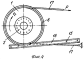
Сущность изобретения поясняется чертежами, где на фиг.1 представлена цистерна-контейнер с демонтированными съемными цилиндрическими юбками, установленная на раме транспортного средства; на фиг.2 изображена концевая часть цистерны-контейнера с установленной на ней цилиндрической юбкой с опорным фланцем; на фиг.3 показана концевая часть цистерны-контейнера с несъемной цилиндрической юбкой, полость которой заполнена порошковым пламегасящим антипиреном; на фиг.4 проиллюстрирован вариант погрузочно-разгрузочной операции цистерны-контейнера посредством перекатывания цистерны по лаговой раме; на фиг.5 показан вариант вертикального складирования цистерны-контейнера.The invention is illustrated by drawings, where figure 1 shows a tank container with dismounted removable cylindrical skirts mounted on the frame of the vehicle; figure 2 shows the end of the tank container with a cylindrical skirt mounted on it with a support flange; figure 3 shows the end of the tank container with a non-removable cylindrical skirt, the cavity of which is filled with a powder flame retardant flame retardant; figure 4 illustrates a variant of the loading and unloading operation of the tank container by rolling the tank along the lag frame; figure 5 shows a variant of the vertical storage of the tank container.
Позиции на чертеже обозначают: 1 - коконообразный резервуар цистерны-контейнера; 2 - запорные крышки, оснащенные заливочными или сливными устройствами и аппаратурой контроля за состоянием груза; 3 - опорные базовые шпангоуты резервуара; 4 - кулачки; 5 - рама транспортного средства; 6 - базирующие ложементы рамы транспортного средства; 7 - скобы; 8 - кольцевые бандажные ободы с ребордами; 9 - замковые ложементы рамы транспортного средства; 10 - цилиндрическая юбка с опорным фланцем; 11 - упругий стакан-амортизатор; 12 - пламегасящая порошковая набивка; 13 - влагозащитная упаковка; 14 - крышка; 15 - лаговая рама; 16 - двутавровые лаги; 17 - буксирный канат.The positions in the drawing indicate: 1 - cocoon-shaped tank of the tank container; 2 - locking caps, equipped with filling or drain devices and equipment for monitoring the state of the load; 3 - supporting basic frames of the tank; 4 - cams; 5 - vehicle frame; 6 - based lodgment of the frame of the vehicle; 7 - staples; 8 - ring retaining rims with flanges; 9 - locking lodgements of the vehicle frame; 10 - a cylindrical skirt with a support flange; 11 - elastic glass shock absorber; 12 - flame retardant powder packing; 13 - moisture-proof packaging; 14 - a cover; 15 - lag frame; 16 - I-beams; 17 - towing rope.
Цистерна-контейнер для транспортирования и хранения жидкостей, сжиженных газов и сыпучих материалов (фиг.1, фиг.2 и фиг.3) содержит высокопрочный жесткий резервуар 1 коконообразной формы, имеющий два полюсных отверстия, задраенные крышками 2, на одной из которых смонтированы заливочные устройства и аппаратура контроля за состоянием груза, а на другой - запорно-сливные устройства и аппаратура дублирующего контроля за состоянием груза. Силовая оболочка резервуара 1 имеет на цилиндрическом участке два опорных базовых шпангоута 3, симметрично расположенных относительно центра масс резервуара. На каждом шпангоуте имеется по два кулачка 4, предназначенных для крепления резервуара на раме 5 транспортного средства, а также для транспортировки грузоподъемными кранами и для кантования цистерны из горизонтального в вертикальное положение. Резервуар 1 своими опорными базовыми шпангоутами 3 укладывается на базирующие ложементы 6 рамы 5 транспортного средства и прикрепляется за кулачки 4 к ней скобами 7. На цилиндрической части резервуара 1 симметрично относительно центра масс загруженной цистерны смонтированы два кольцевых бандажных обода 8 с ребордами, прочно скрепленные с силовой стенкой резервуара, выполненные из твердого износостойкого материала, в частности из стали. Эти бандажные ободы обеспечивают требуемую диаметральную жесткость резервуара и используются в качестве катков при перекатывании цистерны по лагам (фиг.4). Кольцевые бандажные ободы 8 размещаются в пазах замковых элементов 9 рамы транспортного средства и жестко фиксируют ее положение на раме 5, предотвращая ее продольное смещение при транспортировке цистерны-контейнера.The tank container for transporting and storing liquids, liquefied gases and bulk materials (FIG. 1, FIG. 2 and FIG. 3) contains a high-strength rigid cocoon-
Хотя бы на одном конце резервуара 1, по крайней мере со стороны сливного отверстия смонтирована телескопически съемная цилиндрическая юбка 10 с опорным фланцем (фиг.2), используемая для вертикального складирования цистерны-контейнера (фиг.5), которая может иметь смотровые и/или облегчающие окна по круговому периметру юбки. Юбка 10 упирается своим торцевым срезом в торец шпангоута 3 и фиксируется на резервуаре с помощью специальных накидных петель или скоб, накладываемых на кулачки 4.A telescopically removable
Цилиндрическая юбка 10 может быть прочно скреплена с силовой оболочкой резервуара 1 клеевым соединением или сваркой. Для амортизации продольных динамических нагрузок, действующих на цистерну-контейнер при транспортировке, а также для компенсации термоупругих, действующих на днище резервуара со стороны, скрепленной с ним цилиндрической юбкой, между опорным фланцем юбки и днищем резервуара предусмотрен амортизирующий компенсационный упругий стакан 11, например из резины, приклеенный к стенке опорной юбки 10 (фиг.3).The
Внутренняя полость цилиндрической юбки 10 может быть заполнена пламегасящим порошковым веществом 12, расфасованным во влагонепроницаемые, например, пленочные пакеты, или тороидальную оболочку 13 из термопластичного полимера или эластомерного материала. Для защиты аппаратуры контроля за состоянием груза, а также пламегасящей порошковой набивки от атмосферной влаги и других негативных воздействий может быть использована водонепроницаемая крышка 14 (фиг.3).The inner cavity of the
Для снижения сухой массы конструкции цистерны-контейнера, повышения технологичности ее изготовления и эксплуатации, а также увеличения ее долговечности резервуар 1 и/или цилиндрические юбки 10 могут быть выполнены из композиционных материалов. В частности, резервуар цистерны для транспортирования сжиженных газов и нефти наиболее рационально выполнять из высокопрочных намоточных стеклопластиков. Резервуары цистерн, предназначенных для транспортирования и хранения сжиженных газов, скоропортящихся сельскохозяйственных продуктов, а также жидкостей в условиях низких зимних или высоких летних температур должен иметь наружную или/и внутреннюю теплоизоляцию. При этом наружное теплоизоляцинное покрытие наносится на цилиндрические участки внешней поверхности резервуара цистерны-контейнера, расположенные между опорными базовыми шпангоутами 3 и кольцевыми бандажными ободами 8, и оно не должно выступать за внешние диаметральные обводы шпангоутов и бандажных ободов.To reduce the dry weight of the design of the tank container, increase the manufacturability of its manufacture and operation, as well as increase its durability, the
Варианты эксплуатации цистерны-контейнера, характеризующие ее технологические возможности, следующие.Options for the operation of the container tank, characterizing its technological capabilities, are as follows.
Эксплуатация цистерны-контейнера предполагает ее заполнение транспортируемым грузом (жидкостью или сыпучим неслеживающимся материалом); перемещение и установку на транспортное средство (автомобильное, железнодорожное, авиационное или плавающее водное); транспортирование до пункта назначения (на предприятие-потребитель либо на площадку временного складирования: железнодорожную станцию, речной или морской порт); разгрузку цистерны-контейнера и временное складирование: перегрузку на другой вид транспорта и доставку потребителю груза; опорожнение цистерны-контейнера (экстракция груза) или использование ее для хранения доставленного груза до полной его реализации потребителем.The operation of the container tank involves filling it with transported cargo (liquid or loose non-caking material); moving and installing on a vehicle (automobile, railway, aviation or floating water); transportation to the destination (to the consumer enterprise or to the temporary storage site: railway station, river or sea port); unloading of the container tank and temporary storage: reloading to another type of transport and delivery of cargo to the consumer; emptying the container tank (cargo extraction) or using it to store the delivered cargo until it is fully sold by the consumer.
Заполнение цистерны-контейнера может производиться на специализированных эстакадах герметичным или открытым способом при вертикальном положении резервуара (фиг.5). Заполненную цистерну с помощью кранового оборудования или специального приспособления - кантователя кантуют в горизонтальное положение, укладывая на ложементы или лаги кольцевыми бандажными ободами, а затем переносят ее с помощью специальных погрузчиков или перекатыванием по лагам на транспортное средство, устанавливают и закрепляют на нем в горизонтальном положении и затем транспортируют к пункту назначения. При транспортировании крупнотоннажных цистерн-контейнеров воздушным или автомобильным транспортом рационально использовать съемные цилиндрические юбки, которые можно демонтировать и не транспортировать их на место доставки груза, где можно иметь при необходимости местный комплект таких опорных юбок. В пунктах назначения доставленная цистерна-контейнер снимается с транспортного средства с помощью специализированной погрузочно-разгрузочной техники и складируется в складском помещении или на открытой площадке в вертикальном положении (фиг.5) или в горизонтальном. При отсутствии подъездных путей или специализированной погрузочно-разгрузочной техники разгрузка цистерны-контейнера, доставка на площадку временного хранения или перегрузка на другой вид транспорта может осуществляться путем перекатывания цистерн по лаговым рамам 15, состоящим, например, из двух параллельных двутавровых лаг 16, скрепленных между собой поперечными шпалами (фиг.4). При этом используется гибкий буксир 17 в виде каната или резинокордной ленты, один конец которого закрепляют, а второй тянут с помощью лебедки, трактора, автомобиля или гужевой упряжки. Кантование цистерны-контейнера может быть выполнено с помощью подъемного крана, тали или лебедки.Filling the tank container can be done on specialized racks hermetically or openly with the vertical position of the tank (figure 5). The filled tank with the help of crane equipment or a special device - the tilter is turned over horizontally, laid on lodgements or logs with ring retaining rims, and then transferred with special loaders or rolled over the lags onto the vehicle, installed and fixed on it in a horizontal position and then transported to the destination. When transporting large-capacity tank containers by air or by road, it is rational to use removable cylindrical skirts that can be dismantled and not transported to the place of cargo delivery, where you can have a local set of such supporting skirts if necessary. At the destination, the delivered tank container is removed from the vehicle using specialized loading and unloading equipment and stored in a storage room or in an open area in a vertical position (figure 5) or in a horizontal position. In the absence of access roads or specialized loading and unloading equipment, the unloading of the tank container, delivery to the temporary storage site or reloading to another type of transport can be carried out by rolling the tanks along
Вертикальное складирование цистерн-контейнеров на площадках временного хранения, в складских помещениях и в трюмах транспортных плавсредств позволяет более эффективно использовать их площади и объемы. Вертикальное положение цистерны на эстакаде предприятия-потребителя позволяет существенно упростить и сократить время слива жидких грузов и разгрузки сыпучих грузов, используя наименее энергозатратный способ открытого бункерного способа опорожнения резервуара цистерны-контейнера.Vertical storage of tank containers at temporary storage sites, in storage rooms and in the holds of transport vehicles allows more efficient use of their areas and volumes. The vertical position of the tank on the flyover of the consumer enterprise can significantly simplify and reduce the time of liquid cargo discharge and unloading of bulk cargo using the least energy-intensive method of open bunker method of emptying the tank-container tank.
Источники информацииSources of information
1. Контейнерная транспортная система. Л.А.Коган, Ю.Т.Козлов, М.Д.Ситник и др. Под ред. Л.А.Когана. 2-ое издание, перераб. и доп. - М.: Транспорт, 1991. - 254 с. (см. с. 92).1. Container transport system. L.A. Kogan, Yu.T. Kozlov, M.D. Sitnik and others. Ed. L.A. Kogan. 2nd edition, revised. and add. - M.: Transport, 1991 .-- 254 p. (see p. 92).
2. SU, патент 2036121, B 65 D 88/12. Контейнер-цистерна (прототип).2. SU, patent 2036121, B 65 D 88/12. Tank container (prototype).
Claims (14)
Priority Applications (1)
| Application Number | Priority Date | Filing Date | Title |
|---|---|---|---|
| RU2001136056/13A RU2234446C2 (en) | 2001-12-26 | 2001-12-26 | Tank-container |
Applications Claiming Priority (1)
| Application Number | Priority Date | Filing Date | Title |
|---|---|---|---|
| RU2001136056/13A RU2234446C2 (en) | 2001-12-26 | 2001-12-26 | Tank-container |
Publications (2)
| Publication Number | Publication Date |
|---|---|
| RU2001136056A RU2001136056A (en) | 2004-02-27 |
| RU2234446C2 true RU2234446C2 (en) | 2004-08-20 |
Family
ID=33412222
Family Applications (1)
| Application Number | Title | Priority Date | Filing Date |
|---|---|---|---|
| RU2001136056/13A RU2234446C2 (en) | 2001-12-26 | 2001-12-26 | Tank-container |
Country Status (1)
| Country | Link |
|---|---|
| RU (1) | RU2234446C2 (en) |
-
2001
- 2001-12-26 RU RU2001136056/13A patent/RU2234446C2/en not_active IP Right Cessation
Non-Patent Citations (1)
| Title |
|---|
| КОГАН Л.А. и др. Контейнерная транспортная система. - М.: Транспорт, 1991, с.92. АБИБОВ А.Л. и др. Применение конструкционных пластмасс в производстве летательных аппаратов. - М.: Машиностроение, 1971, с.148. * |
Also Published As
| Publication number | Publication date |
|---|---|
| RU2001136056A (en) | 2004-02-27 |
Similar Documents
| Publication | Publication Date | Title |
|---|---|---|
| US3951284A (en) | Device for transporting bulk materials and methods | |
| US3044515A (en) | Self-erecting collapsible containers | |
| US20090134171A1 (en) | Modular tank unit for ship, barge and rail transportation | |
| US20150122821A1 (en) | Iso modal container | |
| US20130001224A1 (en) | Storage tank | |
| WO2016009427A1 (en) | Containers shelter | |
| US10486579B2 (en) | Lightweight transport, storage and delivery system | |
| WO2011048427A2 (en) | Containerisation module for elongate load | |
| US4132310A (en) | Shipping system for liquids and powders | |
| CA2714329C (en) | Storage tank containment apparatus | |
| US9821954B2 (en) | Box for reinforcing a shipping container | |
| WO2013083159A1 (en) | Iso modal container and anchorage structure therefor | |
| RU2234446C2 (en) | Tank-container | |
| US3114384A (en) | Underwater storage system | |
| US5823225A (en) | Collapsible container for hauling bulk materials | |
| US20070089656A1 (en) | Device and a method for stabilizing and controlling the lowering or raising of a structure between the surface and the bed of the sea | |
| EP0013591A1 (en) | Bulk liquid container | |
| US11104510B2 (en) | Lightweight transport, storage, and delivery system | |
| CA2762244A1 (en) | Mobile storage tank with fluid containment | |
| US5950557A (en) | Installation for offshore storage of hazardous waste | |
| AU2007101010A4 (en) | Water storage tank in shipping container | |
| RU108028U1 (en) | SOFT DEPOSIT IN THE CAR | |
| RU2705628C1 (en) | Large-capacity garbage container with end vertical loading and unloading | |
| US3187793A (en) | Amphibious underwater storage system | |
| Olsen et al. | Container Design |
Legal Events
| Date | Code | Title | Description |
|---|---|---|---|
| MM4A | The patent is invalid due to non-payment of fees |
Effective date: 20040713 |
|
| TK4A | Correction to the publication in the bulletin (patent) |
Free format text: AMENDMENT TO CHAPTER -MM4A- IN JOURNAL: 26-2006 |