RU2231663C2 - Actuating mechanism of diesel engine electronic speed control system - Google Patents
Actuating mechanism of diesel engine electronic speed control system Download PDFInfo
- Publication number
- RU2231663C2 RU2231663C2 RU2002122449/06A RU2002122449A RU2231663C2 RU 2231663 C2 RU2231663 C2 RU 2231663C2 RU 2002122449/06 A RU2002122449/06 A RU 2002122449/06A RU 2002122449 A RU2002122449 A RU 2002122449A RU 2231663 C2 RU2231663 C2 RU 2231663C2
- Authority
- RU
- Russia
- Prior art keywords
- electromagnetic
- pressure fuel
- actuating mechanism
- diesel engine
- injection pump
- Prior art date
Links
Images
Landscapes
- High-Pressure Fuel Injection Pump Control (AREA)
- Fuel-Injection Apparatus (AREA)
Abstract
Description
Изобретение относится к двигателям внутреннего сгорания, а более конкретно - к устройствам для автоматического регулирования частоты вращения коленчатого вала дизеля.The invention relates to internal combustion engines, and more particularly to a device for automatically controlling the speed of a diesel engine crankshaft.
Известны электронно-управляемые исполнительные механизмы, применяемые в системах автоматического регулирования частоты вращения дизелей, в которых в качестве электромагнитных исполнительных органов, воздействующих на рейки топливных насосов высокого давления (ТНВД), применяются пропорциональные электромагниты, моментные, линейные или шаговые двигатели, которые могут служить как в качестве непосредственного привода реек ТНВД с небольшими перестановочными усилиями [1] (стр.186), [2, 3], так и в совокупности с механизмами непрямого действия [1] (стр.188), [2] в ТНВД с большими перестановочными усилиями. Кроме того, для привода реек ТНВД с большими перестановочными усилиями используются кинематические цепи, позволяющие получить выигрыш в усилии на рейках или в поворотном моменте на рычагах [4, 5]. Если в качестве электромагнитного исполнительного органа используется электродвигатель, то применение различного вида кинематических цепей обусловлено необходимостью уменьшения угловых перемещений, т.к. перемещения реек обычно незначительны.Known electronically-controlled actuators used in automatic control systems of diesel engine speed, in which proportional electromagnets, torque, linear or stepper motors are used as electromagnetic actuators acting on the racks of high-pressure fuel pumps (TNVD), which can serve as as a direct drive of the injection pump rails with small permutation forces [1] (p. 186), [2, 3], and in conjunction with mechanisms of indirect action [1] (p. 188), [2] in the high-pressure fuel pump with large permutation forces. In addition, kinematic chains are used to drive the high-pressure fuel pump rails with large permutation forces, which allow gaining in effort on the rails or in the turning moment on the levers [4, 5]. If an electric motor is used as an electromagnetic actuator, then the use of various types of kinematic chains is due to the need to reduce angular displacements, because the movements of the rails are usually insignificant.
Линейные электромагнитные исполнительные органы, непосредственно связанные с рейками топливных насосов высокого давления, например [1], (стр.186) и [3], обладают достаточной точностью и быстродействием, однако использование их для привода реек топливных насосов высокого давления ограничивается габаритными размерами электромагнитов.Linear electromagnetic actuators directly connected to the racks of high-pressure fuel pumps, for example [1], (p. 186) and [3], have sufficient accuracy and speed, but their use for driving the racks of high-pressure fuel pumps is limited by the overall dimensions of the electromagnets.
Таким образом, очевидно, что с целью обеспечения необходимых точности и быстродействия рассматриваемый привод должен быть приводом непосредственного воздействия электромагнитного исполнительного органа на рейку ТНВД. При использовании V-образного ТНВД, имеющего две рейки, лучше всего использовать поворотный электромагнитный исполнительный орган, установив его с возможностью одинакового воздействия сразу на обе рейки [4] (прототип).Thus, it is obvious that in order to ensure the necessary accuracy and speed, the drive in question should be the drive of the direct impact of the electromagnetic actuator on the injection pump rail. When using a V-shaped injection pump having two rails, it is best to use a rotary electromagnetic actuator, setting it with the possibility of the same effect on both rails at once [4] (prototype).
Однако указанный прототип обладает рядом недостатков, препятствующих достижению требуемой точности позиционирования реек ТНВД и скорости их установки в нужное положение, поскольку кинематическая цепь получается чересчур длинной, имеющей много зазоров в сопряжениях пар трения. Электромагнитный исполнительный механизм для обеспечения нормальной работы дизеля должен работать в условиях частого реверса, при котором неизбежна "перекладка" зазоров и износ в парах трения. Другим условием обеспечения необходимой точности позиционирования реек ТНВД является наличие обратной связи с электронным блоком управления, что в конструкции прототипа не проработано совсем. Кроме того, конструкция прототипа имеет чрезмерные вертикальные габаритные размеры, что усложняет компоновку дизеля с кабиной, расположенной над ним, поэтому возникает необходимость уменьшения вертикальных габаритных размеров и расположения корпуса электромагнитного исполнительного органа в развале ТНВД.However, this prototype has a number of disadvantages that impede the achievement of the required accuracy of positioning the high pressure fuel rail and the speed of their installation in the desired position, since the kinematic chain is too long, with many gaps in the mating friction pairs. The electromagnetic actuator to ensure the normal operation of the diesel engine must work under conditions of frequent reverse, in which the "shifting" of gaps and wear in friction pairs is inevitable. Another condition for ensuring the necessary accuracy of the positioning of the injection pump rails is the presence of feedback with the electronic control unit, which is not worked out at all in the prototype design. In addition, the design of the prototype has excessive vertical overall dimensions, which complicates the layout of the diesel engine with a cabin located above it, so there is a need to reduce the vertical overall dimensions and the location of the body of the electromagnetic actuating body in the collapse of the injection pump.
В качестве исполнительного органа могут применяться многополярные нейтральные или поляризованные поворотные электромагниты с диапазоном перемещения выходного вала, соответствующим полному ходу реек топливного насоса высокого давления. На валу поляризованных электромагнитов устанавливается многополярно намагниченный постоянный магнит, а на корпусе установлены электромагниты, соответствующие полюсам постоянного магнита. Точность позиционирования, быстродействие и развиваемый поворотный момент таких устройств значительно выше, чем поворотных позиционных нейтральных электромагнитов.As an executive body, multipolar neutral or polarized rotary electromagnets with a range of movement of the output shaft corresponding to the full travel of the racks of the high-pressure fuel pump can be used. A multipolarized permanent magnet is mounted on the shaft of polarized electromagnets, and electromagnets corresponding to the poles of the permanent magnet are mounted on the housing. The positioning accuracy, speed and the developed turning moment of such devices are much higher than rotary positional neutral electromagnets.
Поэтому предлагаемая конструкция исполнительного механизма электронной системы регулирования частоты вращения дизеля дополнительно оснащена бесконтактным датчиком положения выходного вала электромагнитного исполнительного органа, непосредственно и жестко связанного с двуплечим рычагом, причем корпус электромагнитного исполнительного органа размещен под крышкой в развале V-образного топливного насоса высокого давления.Therefore, the proposed design of the actuator of the electronic diesel engine speed control system is additionally equipped with a non-contact position sensor for the output shaft of the electromagnetic actuator, which is directly and rigidly connected to the two-arm lever, the housing of the electromagnetic actuator located under the lid in the collapse of the V-shaped high-pressure fuel pump.
Кроме того, в качестве электромагнитного исполнительного органа используется многополярный поляризованный поворотный электромагнит.In addition, a multipolar polarized rotary electromagnet is used as the electromagnetic actuator.
В этом заключается сущность изобретения.This is the essence of the invention.
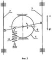
Наличие датчика положения выходного вала электромагнитного исполнительного органа, непосредственной жесткой связи его с двуплечим рычагом реек ТНВД и размещение корпуса электромагнитного исполнительного органа в развале V-образного ТНВД представляют собой признаки существенного отличия предлагаемого изобретения от прототипа. На фиг.1 изображена общая компоновка исполнительного механизма электронной системы регулирования частоты вращения дизеля, на фиг.2 - его кинематическая схема.The presence of the position sensor of the output shaft of the electromagnetic actuator, its direct rigid connection with the two-arm lever of the high-pressure fuel rail rods and the placement of the electromagnetic actuator body in the collapse of the V-shaped high-pressure fuel pump are signs of a significant difference between the present invention and the prototype. In Fig.1 shows the General layout of the actuator of the electronic system for controlling the speed of a diesel engine, Fig.2 - its kinematic diagram.
Устройство состоит из следующих элементов. Корпус 1 электромагнитного исполнительного органа помещен в развал V-образного ТНВД 2 и жестко закреплен на его крышке 3. На выходной вал 4 электромагнитного исполнительного органа с одной стороны установлен бесконтактный датчик 5 его положения, электрически связанный с электронным блоком управления ЭБУ, двуплечий рычаг 6 реек 7 ТНВД 2. На кулачковом валу 8 ТНВД 2 жестко установлено зубчатое колесо 9 датчика 10 частоты вращения, электрически связанного с электронным блоком управления ЭБУ; возвратная пружина 11 исполнительного органа одним концом соединена с двуплечим рычагом 6, а другим с корпусом ТНВД 2.The device consists of the following elements. The
Устройство работает следующим образом. Электронный блок управления ЭБУ на основании информации с датчиков 5 и 10 вырабатывает управляющий сигнал для привода в действие электромагнитного исполнительного органа 1. В результате поворота выходного вала 4 двуплечий рычаг 6 поворачивается совместно с ним, причем при повороте по часовой стрелке он перемещает рейки 7 на увеличение подачи топлива, а при повороте против часовой стрелки - на уменьшение. Гарантированное отключение подачи топлива при выключении из работы исполнительного механизма электронной системы регулирования частоты вращения дизеля осуществляется посредством возвратной пружины 11.The device operates as follows. Based on information from sensors 5 and 10, the ECU electronic control unit generates a control signal for driving the
Экономический эффект от внедрения исполнительного механизма следует ожидать от улучшения качества работы дизеля на переходных процессах, обеспечивающего уменьшение путевого расхода топлива и вредных выбросов в атмосферу.The economic effect of the introduction of the actuator should be expected from an improvement in the quality of diesel engine operation in transients, which ensures a decrease in travel fuel consumption and harmful emissions into the atmosphere.
Источники информацииSources of information
1. Фанлейб Б.Н. Топливная аппаратура автотракторных дизелей: Справочник. - 2-е изд., перераб. и доп. - Л.: Машиностроение. Ленингр. отд-е, 1990. - 352 с.1. Fanleib B.N. Fuel equipment of automotive diesel engines: Reference book. - 2nd ed., Revised. and add. - L .: Mechanical engineering. Leningra. Dep., 1990. - 352 p.
2. Schartz R. High - Pressure injection pumps with electronic control for heavy-duty diesel engines // SAE Technical Paper. - 1985. - №850170. - 13 р.2. Schartz R. High - Pressure injection pumps with electronic control for heavy-duty diesel engines // SAE Technical Paper. - 1985. - No. 850170. - 13 p.
3. Пат. 2066386 РФ, 6 F 02 D 1/08, 1/18. Электронный регулятор частоты вращения для управления подачей топлива топливным наосом высокого давления. / С.П.Гладышев, В.М.Бунов, А.В.Лосев и др. - 1996.3. Pat. 2066386 RF, 6 F 02
4. А.С. 1318706 СССР, F 02 D 1/08. Исполнительный механизм электронного регулятора частоты вращения дизеля. / В.В.Курманов, Е.В.Пугин, Н.Ф.Лимаров и др. // Открытия. Изобретения. - 1987, №23 (прототип).4. A.S. 1318706 USSR, F 02
5. Diesel Engine Management Systems. - Autodata. - 2000. - Vol. 5, P. 35.5. Diesel Engine Management Systems. - Autodata. - 2000. - Vol. 5, p. 35.
Claims (2)
Priority Applications (1)
| Application Number | Priority Date | Filing Date | Title |
|---|---|---|---|
| RU2002122449/06A RU2231663C2 (en) | 2002-08-19 | 2002-08-19 | Actuating mechanism of diesel engine electronic speed control system |
Applications Claiming Priority (1)
| Application Number | Priority Date | Filing Date | Title |
|---|---|---|---|
| RU2002122449/06A RU2231663C2 (en) | 2002-08-19 | 2002-08-19 | Actuating mechanism of diesel engine electronic speed control system |
Publications (2)
| Publication Number | Publication Date |
|---|---|
| RU2002122449A RU2002122449A (en) | 2004-02-20 |
| RU2231663C2 true RU2231663C2 (en) | 2004-06-27 |
Family
ID=32845995
Family Applications (1)
| Application Number | Title | Priority Date | Filing Date |
|---|---|---|---|
| RU2002122449/06A RU2231663C2 (en) | 2002-08-19 | 2002-08-19 | Actuating mechanism of diesel engine electronic speed control system |
Country Status (1)
| Country | Link |
|---|---|
| RU (1) | RU2231663C2 (en) |
Cited By (4)
| Publication number | Priority date | Publication date | Assignee | Title |
|---|---|---|---|---|
| RU2299342C1 (en) * | 2006-01-10 | 2007-05-20 | Государственное образовательное учреждение высшего профессионального образования "Южно-Уральский государственный университет" | Diesel engine fuel supply control electronic regulator |
| RU2363854C2 (en) * | 2007-06-06 | 2009-08-10 | ОАО "Ярославский завод дизельной аппаратуры" | Actuating mechanism of electronic system of in-line diesel engine control in high-pressure fuel pump |
| RU2502884C1 (en) * | 2012-08-13 | 2013-12-27 | Федеральное государственное бюджетное образовательное учреждение высшего профессионального образования "Брянский государственный технический университет" | Automatic self-adjusting microprocessor-based system for thermal machine shaft rpm control |
| RU2518725C1 (en) * | 2013-01-29 | 2014-06-10 | Федеральное государственное унитарное предприятие "Научно-производственное объединение автоматики имени академика Н.А. Семихатова" | Diesel in-line high-pressure fuel pump electronic control system actuator |
Citations (5)
| Publication number | Priority date | Publication date | Assignee | Title |
|---|---|---|---|---|
| GB1462871A (en) * | 1973-04-14 | 1977-01-26 | Cav Ltd | Actuator mechanism for a fuel injection pump control member |
| FR2451462A1 (en) * | 1979-03-10 | 1980-10-10 | Bosch Gmbh Robert | FUEL INJECTION PUMP FOR INTERNAL COMBUSTION ENGINE |
| SU1318706A1 (en) * | 1986-01-07 | 1987-06-23 | Ярославский завод дизельной аппаратуры | Actuating mechanism of diesel engine rotational speed electronic governor |
| DE4117267A1 (en) * | 1991-05-27 | 1992-12-03 | Bosch Gmbh Robert | FUEL INJECTION PUMP FOR INTERNAL COMBUSTION ENGINES |
| RU2066386C1 (en) * | 1993-12-10 | 1996-09-10 | Челябинский государственный технический университет | Electronic speed governor to control fuel delivery by high-pressure fuel injection pump |
-
2002
- 2002-08-19 RU RU2002122449/06A patent/RU2231663C2/en not_active IP Right Cessation
Patent Citations (5)
| Publication number | Priority date | Publication date | Assignee | Title |
|---|---|---|---|---|
| GB1462871A (en) * | 1973-04-14 | 1977-01-26 | Cav Ltd | Actuator mechanism for a fuel injection pump control member |
| FR2451462A1 (en) * | 1979-03-10 | 1980-10-10 | Bosch Gmbh Robert | FUEL INJECTION PUMP FOR INTERNAL COMBUSTION ENGINE |
| SU1318706A1 (en) * | 1986-01-07 | 1987-06-23 | Ярославский завод дизельной аппаратуры | Actuating mechanism of diesel engine rotational speed electronic governor |
| DE4117267A1 (en) * | 1991-05-27 | 1992-12-03 | Bosch Gmbh Robert | FUEL INJECTION PUMP FOR INTERNAL COMBUSTION ENGINES |
| RU2066386C1 (en) * | 1993-12-10 | 1996-09-10 | Челябинский государственный технический университет | Electronic speed governor to control fuel delivery by high-pressure fuel injection pump |
Cited By (4)
| Publication number | Priority date | Publication date | Assignee | Title |
|---|---|---|---|---|
| RU2299342C1 (en) * | 2006-01-10 | 2007-05-20 | Государственное образовательное учреждение высшего профессионального образования "Южно-Уральский государственный университет" | Diesel engine fuel supply control electronic regulator |
| RU2363854C2 (en) * | 2007-06-06 | 2009-08-10 | ОАО "Ярославский завод дизельной аппаратуры" | Actuating mechanism of electronic system of in-line diesel engine control in high-pressure fuel pump |
| RU2502884C1 (en) * | 2012-08-13 | 2013-12-27 | Федеральное государственное бюджетное образовательное учреждение высшего профессионального образования "Брянский государственный технический университет" | Automatic self-adjusting microprocessor-based system for thermal machine shaft rpm control |
| RU2518725C1 (en) * | 2013-01-29 | 2014-06-10 | Федеральное государственное унитарное предприятие "Научно-производственное объединение автоматики имени академика Н.А. Семихатова" | Diesel in-line high-pressure fuel pump electronic control system actuator |
Also Published As
| Publication number | Publication date |
|---|---|
| RU2002122449A (en) | 2004-02-20 |
Similar Documents
| Publication | Publication Date | Title |
|---|---|---|
| US6792903B2 (en) | Mechanical control of the intake valve lift adjustment in an internal combustion engine | |
| JP4962370B2 (en) | Variable valve mechanism for internal combustion engine | |
| KR960702883A (en) | A LARGE TWO-STROKE INTERNAL COMBUSTION ENGINE | |
| KR960702882A (en) | A SLIDE VALVE AND A LARGE TWO-STROKE INTERNAL COMBUSTION ENGINE | |
| US4791895A (en) | Electro-magnetic-hydraulic valve drive for internal combustion engines | |
| SE0301714L (en) | Ways to control the conversion of the valves in an internal combustion engine with variable valve timing and vehicles with such an engine with electronic control means for valve control | |
| US20140102389A1 (en) | Internal combustion engine valve drive device for a motor vehicle | |
| RU2231663C2 (en) | Actuating mechanism of diesel engine electronic speed control system | |
| US5144920A (en) | Automatic timing governor between crankshaft and camshafts, operating by means of actuators on the shaft connecting chain | |
| AU3461393A (en) | Variable timing gear device | |
| WO2005026519A3 (en) | Electronic fuel regulation system for small engines | |
| EP2837804A1 (en) | Operating internal combustion engines | |
| US20180320561A1 (en) | Valve Train Device | |
| CN105074144B (en) | Valve device for internal combustion engine | |
| US1201055A (en) | Multiple-cylinder motor. | |
| KR100932676B1 (en) | Arrangement method of incremental position sensor | |
| CN112189081B (en) | Valve drive device with switching device | |
| RU2198313C2 (en) | Device for and method of control of transport diesel engine fuel injection moment | |
| SE455520B (en) | DEVICE FOR THE OPERATION OF THE FUEL LENGTH OF A INJECTION PUMP TO A DIESEL TYPE COMBUSTION ENGINE | |
| KR100622761B1 (en) | Variable balance shaft using electromagnet clutch | |
| SE9603641L (en) | Rocker arm for propelling fuel injectors | |
| CN200978728Y (en) | Electronic speed-regulator for diesel engine | |
| EP2826964A1 (en) | Variable actuation timing device | |
| RU2390817C2 (en) | Electromagnetic actuator with x-shaped spring hinge | |
| JPH03512Y2 (en) |
Legal Events
| Date | Code | Title | Description |
|---|---|---|---|
| MM4A | The patent is invalid due to non-payment of fees |
Effective date: 20100820 |