RU2230697C2 - Device for and method of checking containers on conveyor line - Google Patents
Device for and method of checking containers on conveyor line Download PDFInfo
- Publication number
- RU2230697C2 RU2230697C2 RU99121409/03A RU99121409A RU2230697C2 RU 2230697 C2 RU2230697 C2 RU 2230697C2 RU 99121409/03 A RU99121409/03 A RU 99121409/03A RU 99121409 A RU99121409 A RU 99121409A RU 2230697 C2 RU2230697 C2 RU 2230697C2
- Authority
- RU
- Russia
- Prior art keywords
- belt
- conveyor
- container
- guide
- speed
- Prior art date
Links
- 0 C1CC*CC1 Chemical compound C1CC*CC1 0.000 description 1
Images


Classifications
-
- G—PHYSICS
- G01—MEASURING; TESTING
- G01N—INVESTIGATING OR ANALYSING MATERIALS BY DETERMINING THEIR CHEMICAL OR PHYSICAL PROPERTIES
- G01N21/00—Investigating or analysing materials by the use of optical means, i.e. using sub-millimetre waves, infrared, visible or ultraviolet light
- G01N21/84—Systems specially adapted for particular applications
- G01N21/88—Investigating the presence of flaws or contamination
- G01N21/90—Investigating the presence of flaws or contamination in a container or its contents
- G01N21/9009—Non-optical constructional details affecting optical inspection, e.g. cleaning mechanisms for optical parts, vibration reduction
-
- B—PERFORMING OPERATIONS; TRANSPORTING
- B65—CONVEYING; PACKING; STORING; HANDLING THIN OR FILAMENTARY MATERIAL
- B65G—TRANSPORT OR STORAGE DEVICES, e.g. CONVEYORS FOR LOADING OR TIPPING, SHOP CONVEYOR SYSTEMS OR PNEUMATIC TUBE CONVEYORS
- B65G47/00—Article or material-handling devices associated with conveyors; Methods employing such devices
- B65G47/22—Devices influencing the relative position or the attitude of articles during transit by conveyors
- B65G47/24—Devices influencing the relative position or the attitude of articles during transit by conveyors orientating the articles
- B65G47/244—Devices influencing the relative position or the attitude of articles during transit by conveyors orientating the articles by turning them about an axis substantially perpendicular to the conveying plane
-
- Y—GENERAL TAGGING OF NEW TECHNOLOGICAL DEVELOPMENTS; GENERAL TAGGING OF CROSS-SECTIONAL TECHNOLOGIES SPANNING OVER SEVERAL SECTIONS OF THE IPC; TECHNICAL SUBJECTS COVERED BY FORMER USPC CROSS-REFERENCE ART COLLECTIONS [XRACs] AND DIGESTS
- Y10—TECHNICAL SUBJECTS COVERED BY FORMER USPC
- Y10S—TECHNICAL SUBJECTS COVERED BY FORMER USPC CROSS-REFERENCE ART COLLECTIONS [XRACs] AND DIGESTS
- Y10S209/00—Classifying, separating, and assorting solids
- Y10S209/917—Endless belt pusher feeding item
Abstract
Description
Данное изобретение касается электрооптического контроля тары, а именно способа и устройства для проверки коммерческих изменений тары во время ее транспортировки по линейному конвейеру.This invention relates to electro-optical control of containers, namely, a method and device for checking commercial changes in containers during transportation along a linear conveyor.
К настоящему времени предложено применение электрооптических методов обнаружения коммерческих изменений в таре из стекла или пластмассы. Термин “коммерческие изменения” относится к изменениям с точки зрения нормативной конструкции и касается тех изменений, которые могут отрицательно сказаться на коммерческой приемлемости тары. К коммерческим изменениям можно отнести, например, изменения в цвете или размерах по сравнению с теми, которые желательны для изготовителя или потребителя; поверхностные изменения, особенно вокруг запечатанной поверхности тары; или аномалии в стенке тары, возникающие при изготовлении, например трещины.To date, the use of electro-optical methods for detecting commercial changes in containers made of glass or plastic has been proposed. The term “commercial changes” refers to changes in terms of regulatory design and refers to those changes that could adversely affect the commercial acceptability of containers. Commercial changes include, for example, changes in color or size compared to those that are desirable to the manufacturer or consumer; surface changes, especially around the sealed container surface; or anomalies in the packaging wall that occur during manufacture, such as cracks.
Патент США № 4874940 раскрывает способ и устройство для проверки тары во время ее транспортирования по линейному конвейеру. Это устройство содержит манипулятор, расположенный под углом над конвейером, для зацепления и поперечного отвода тары, когда конвейер придвигает ее встык к манипулятору. (Определяющие направление прилагательные, такие как “поперечный” и “продольный”, следует понимать относительно направления движения линейного конвейера, если нет иных оговорок.) Отведенную тару приводят в зацепление с приводным ремнем, который отделен поперечным зазором от конвейера и взаимодействует с параллельной секцией манипулятора, чтобы продвигать тару продольно по компенсирующей износ пластине, при этом поворачивая каждую единицу тары вокруг ее центральной оси. Источник света, установленный под компенсирующей износ пластиной, направляет линейный луч света через прорезь в пластине и через тару во время ее поворачивания и транспортирования по компенсирующей износ пластине в камеру, установленную над пластиной. Камера связана с соответствующими электронными средствами для обнаружения коммерческих изменений в таре в зависимости от световой энергии, попадающей на камеру. При транспортировании вдоль прорези компенсирующей износ пластины тару приводят в зацепление вторым приводным ремнем, который расположен под некоторым углом к продольному направлению конвейера для отклонения тары последовательно назад на конвейер.US patent No. 4874940 discloses a method and apparatus for checking containers during transportation along a linear conveyor. This device contains a manipulator, located at an angle above the conveyor, for engaging and lateral removal of the container when the conveyor moves it end-to-end to the manipulator. (Directional adjectives, such as “transverse” and “longitudinal”, should be understood with respect to the direction of movement of the linear conveyor, unless otherwise stated.) The withdrawn packaging is engaged with the drive belt, which is separated by a transverse clearance from the conveyor and interacts with the parallel section of the manipulator to advance the container longitudinally along the wear-compensating plate, while turning each unit of the container around its central axis. A light source mounted under the wear-compensating plate directs a linear beam of light through a slot in the plate and through the container during rotation and transportation through the wear-compensating plate to a chamber mounted above the plate. The camera is connected to appropriate electronic means for detecting commercial changes in the container depending on the light energy incident on the camera. During transportation along the slot of the wear-compensating plate, the container is brought into engagement by a second drive belt, which is located at an angle to the longitudinal direction of the conveyor to deflect the container sequentially back to the conveyor.
Хотя раскрываемые в указанном патенте способ и устройство направлены на решение проблем, имевшихся к тому времени в данной области техники, все же остаются желательными дальнейшие усовершенствования. В частности, задача данного изобретения заключается в обеспечении способа и устройства для проверки тары на линии, в общем являющихся способом и устройством, раскрытыми в указанном патенте, но при которых снижают неустойчивость тары на входном и/или выходном концах устройства. Неустойчивость тары может привести к неровному ходу, сталкиванию друг с другом, падению тары, что, в свою очередь, потребует ручного вмешательства со стороны оператора для восстановления необходимого порядка работы станции проверки. Другая задача данного изобретения заключается в обеспечении способа и устройства описываемого выше типа, которые отличаются удобством удаления тары в случае затора или по другим причинам и прекращают работу станции проверки в случае такого затора. Еще одна задача данного изобретения заключается в обеспечении способа и устройства описываемого выше типа, отличающихся пониженными требованиями технического обслуживания и повышенным сроком службы. Еще одна задача данного изобретения заключается в обеспечении способа и устройства описываемого выше типа, которые можно удобно адаптировать для применения с объемной тарой, т.е. такой, как сосуды с большим сравнительно с длиной оси диаметром. Еще одна задача изобретения заключается в обеспечении способа и устройства описываемого выше типа, которые отличаются удобством регулировки и возможностью регулировки во время работы. Еще одна задача изобретения заключается в обеспечении способа и устройства, которые реализуют одну или более указанных задач и которые можно удобным образом адаптировать для имеющихся проверочных установок вместо устройства, раскрываемого в вышеуказанном патенте.Although the method and device disclosed in the aforementioned patent are aimed at solving the problems that existed by that time in the art, further improvements remain desirable. In particular, the object of the present invention is to provide a method and apparatus for checking containers on a line, generally being the method and device disclosed in said patent, but which reduce the instability of the containers at the input and / or output ends of the device. The instability of the container can lead to uneven running, collision with each other, falling containers, which, in turn, will require manual intervention on the part of the operator to restore the necessary operation of the inspection station. Another objective of the present invention is to provide a method and device of the type described above, which are distinguished by the convenience of removing containers in the event of congestion or for other reasons, and stop the operation of the inspection station in the event of such congestion. Another objective of the present invention is to provide a method and device of the type described above, characterized by reduced maintenance requirements and increased service life. Another objective of this invention is to provide a method and device of the type described above, which can be conveniently adapted for use with bulk containers, i.e. such as vessels with a large diameter compared with the axis length. Another objective of the invention is to provide a method and device of the type described above, which are distinguished by ease of adjustment and the ability to adjust during operation. Another objective of the invention is to provide a method and device that implement one or more of these tasks and which can be conveniently adapted for existing test installations instead of the device disclosed in the above patent.
Перечисленные выше задачи решаются тем, что в устройстве для последовательной проверки тары, проходящей по линейному конвейеру, содержащем подающее средство, нависающее над конвейером для отвода тары в поперечном направлении по меньшей мере частично с конвейера, средство упора, оптические средства для проверки тары при ее повороте во время хода вдоль указанного средства упора и разгрузочное средство для возврата тары назад на конвейер, согласно изобретению подающее средство содержит первый бесконечный приводной ремень, имеющий продольный участок, параллельный конвейеру, и нависающую над конвейером подающую часть, расположенную под острым углом в направлении движения конвейера, для зацепления встык с тарой, установленной с возможностью последовательного прохождения по конвейеру, первый двигатель для привода в движение первого ремня для по меньшей мере частичного отвода тары с конвейера в поперечном направлении, при этом средство упора расположено напротив первого ремня для зацепления встык с тарой, установленной с возможностью отвода от конвейера подающим средством во время движения вдоль средства упора и ее поворота при зацеплении между первым ремнем и средством упора тары, а разгрузочное средство расположено рядом со средством упора для последовательного зацепления и возврата тары назад на конвейер.The above problems are solved by the fact that in the device for sequentially checking containers passing through a linear conveyor containing a supply means hanging over the conveyor to discharge containers in the transverse direction at least partially from the conveyor, stop means, optical means for checking containers when turning during a run along said stop means and unloading means for returning containers back to the conveyor, according to the invention, the supply means comprises a first endless drive belt having a longitudinal the first section parallel to the conveyor, and the feeding part hanging over the conveyor, located at an acute angle in the direction of movement of the conveyor, to engage end-to-end with a container installed with the possibility of sequential passage along the conveyor, the first engine to drive the first belt for at least partial retraction containers from the conveyor in the transverse direction, while the stop means is located opposite the first belt to engage end-to-end with a container installed with the possibility of withdrawing feeding means from the conveyor ohm while moving along the stop means and its rotation when engaged between the first belt and the container stop means, and the unloading means is located next to the stop means for sequential engagement and returning the container back to the conveyor.
В предпочтительном варианте устройство содержит второй приводной ремень, связанный с первым приводным ремнем и первым двигателем и расположенный напротив разгрузочного средства для отвода тары назад на конвейер.In a preferred embodiment, the device comprises a second drive belt connected to the first drive belt and the first engine and located opposite the unloading means for taking the container back to the conveyor.
При этом желательно, чтобы разгрузочное средство содержало третий бесконечный ремень, имеющий средство для приведения его в движение, расположенный с возможностью зацепления тары между вторым и третьим ремнями для отвода тары последовательно назад на конвейер с пониженной скоростью, согласованной со скоростью конвейера.In this case, it is desirable that the unloading means comprise a third endless belt having means for driving it, arranged to engage the containers between the second and third belts for withdrawing the containers sequentially back to the conveyor at a reduced speed consistent with the speed of the conveyor.
Целесообразно, чтобы устройство содержало средство, связывающее второй ремень с первым ремнем, для приведения в движение второго ремня со скоростью меньшей, чем скорость первого ремня, а средство для приведения в движение третьего ремня имело второй двигатель.It is advisable that the device contains means connecting the second belt to the first belt for driving the second belt at a speed lower than the speed of the first belt, and the means for driving the third belt had a second engine.
Возможно также, чтобы первый и третий ремни, первый двигатель и средство, связывающее второй ремень с первым ремнем, были установлены на каретке, выполненной с возможностью регулируемого позиционирования относительно конвейера.It is also possible that the first and third belts, the first engine and the means connecting the second belt to the first belt, are mounted on the carriage, which is made with the possibility of adjustable positioning relative to the conveyor.
В еще одном предпочтительном варианте выполнения средство упора содержит направляющую, расположенную с возможностью поперечного перемещения в направлении по отношению к первому ремню, и средство для упругого приближения направляющей к первому ремню.In yet another preferred embodiment, the abutment means comprises a guide arranged for lateral movement in a direction with respect to the first belt, and means for resiliently approaching the guide to the first belt.
При этом целесообразно, чтобы средство упора содержало средство, ориентирующее направляющую для поворотного движения в сторону от первого ремня.In this case, it is advisable that the stop means comprise means orienting the guide for pivoting movement away from the first belt.
Средство, ориентирующее направляющую, может содержать пару стоек, расположенных с интервалом между ними в продольном направлении направляющей, а средство упругого приближения направляющей к первому ремню может содержать пружину, расположенную в зацеплении с каждой из указанных стоек.The tool orienting the guide may contain a pair of struts located at intervals between them in the longitudinal direction of the guide, and the means of resilient approximation of the guide to the first belt may contain a spring located in engagement with each of these racks.
Желательно оснастить устройство средством для регулирования усилия пружины, расположенной с возможностью приближения направляющей к первому ремню, а также средством для реагирования на отклонение направляющей в сторону от первого ремня и индикации при заторе тары в устройстве.It is advisable to equip the device with means for regulating the force of the spring, which is positioned to approximate the guide to the first belt, as well as means for responding to the deviation of the guide away from the first belt and indication when the container is jammed in the device.
При этом желательно, чтобы реагирующее на отклонение средство имело концевой выключатель.In this case, it is desirable that the deviation responsive means has a limit switch.
В другом предпочтительном варианте устройство содержит средство, связывающее концевой выключатель с первым двигателем, для остановки первого двигателя при срабатывании концевого выключателя.In another preferred embodiment, the device comprises means for connecting the limit switch to the first motor to stop the first motor when the limit switch is activated.
Желательно, кроме того, оснастить устройство первой и второй направляющими, расположенными относительно друг от друга с вертикальным интервалом.It is also desirable to equip the device with first and second guides located relative to each other with vertical spacing.
При этом возможно каждую направляющую снабдить эластомерным средством для упругого зацепления с тарой.In this case, it is possible to provide each guide with elastomeric means for resilient engagement with the container.
Целесообразно, чтобы расположенная под углом в направлении движения конвейера нависающая над конвейером подающая часть первого ремня была установлена с возможностью захвата тары на конвейере, а направляющая имела подающую часть, расположенную под углом и напротив подающей части первого ремня.It is advisable that the feed portion of the first belt, which is located at an angle in the direction of movement of the conveyor, hanging over the conveyor, is mounted with the possibility of picking up containers on the conveyor, and the guide has a feed portion that is located at an angle and opposite the feed portion of the first belt.
Желательно также, чтобы направляющая содержала средство для регулирования положения подающей части направляющей относительно подающей части первого ремня в направлении движения конвейера для перемещения тары разного диаметра.It is also desirable that the guide contains means for adjusting the position of the feed part of the guide relative to the feed part of the first belt in the direction of movement of the conveyor to move containers of different diameters.
Возможно, чтобы средство для регулирования положения подающей части направляющей содержало первую и вторую пластины для обеспечения фиксированного положения направляющей, причем одна из пластин имела бы резьбу, а другая из указанных пластин имела карман напротив указанной резьбы, в котором было бы расположено средство резьбового регулирования в зацеплении с резьбой.It is possible that the means for adjusting the position of the feed portion of the guide comprises first and second plates to ensure a fixed position of the guide, one of the plates having a thread and the other of these plates having a pocket opposite the specified thread, in which the means for adjusting the threaded engagement would be located threaded.
Предпочтительно, чтобы средство для регулирования положения подающей части направляющей содержало также средство для фиксирования пластин в отрегулированном положении.Preferably, the means for adjusting the position of the feed portion of the guide also comprises means for fixing the plates in the adjusted position.
При этом целесообразно, чтобы средство для регулирования положения подающей части направляющей было расположено у конца подающей части направляющей и было бы предусмотрено опорное средство для скольжения разгрузочного конца направляющей и продольного регулирования направляющей.In this case, it is advisable that the means for adjusting the position of the feeding part of the guide be located at the end of the feeding part of the guide and supporting means for sliding the unloading end of the guide and the longitudinal regulation of the guide would be provided.
В еще одном предпочтительном варианте выполнения средство упора выполнено в виде четвертого приводного ремня, имеющего двигатель для его привода в направлении, противоположном направлению первого ремня, для повышения скорости поворачивания тары во время ее прохождения через средства для проверки тары.In another preferred embodiment, the stop means is made in the form of a fourth drive belt having a motor for driving it in the opposite direction to the first belt to increase the speed of rotation of the container during its passage through the means for checking the container.
При этом целесообразно, чтобы четвертый приводной ремень и двигатель были установлены на каретке с возможностью регулирования положения относительно конвейера.It is advisable that the fourth drive belt and engine are mounted on the carriage with the possibility of adjusting the position relative to the conveyor.
Способ проверки тары, идущей на линейном конвейере на первой скорости, согласно изобретению состоит в том, что позиционируют первый приводимый в движение двигателем ремень, нависающий над конвейером, для отвода тары с конвейера в поперечном направлении с упором в средство упора, транспортируют тару между первым ремнем и средством упора на второй скорости, превышающей первую скорость, при одновременном поворачивании тары, осуществляют оптическую проверку тары при ее поворачивании на повышенной скорости и затем отводят тару последовательно между вторым и третьим приводимыми в движение двигателем ремнями назад на конвейер на скорости, соответствующей первой скорости.A method of checking containers running on a linear conveyor at a first speed according to the invention consists in positioning a first engine-driven belt hanging over the conveyor to move the containers from the conveyor in the transverse direction with an emphasis into the stop means, transport the container between the first belt and means of emphasis at a second speed exceeding the first speed, while rotating the container, carry out an optical check of the container when it is rotated at an increased speed, and then the follower packaging is retracted Between the second and third engine-driven belts, back to the conveyor at a speed corresponding to the first speed.
В предпочтительном варианте упор осуществляют направляющей, которую упруго придвигают к первому ремню, и контролируют потенциальный затор тары между направляющей и первым ремнем, при этом передвигают направляющую в сторону от первого ремня.In a preferred embodiment, the stop is carried out by a guide, which is elastically pushed to the first belt, and the potential jam of the container between the guide and the first belt is controlled, while the guide is moved away from the first belt.
Целесообразно прекращать работу первого ремня при обнаружении потенциального затора тары между направляющей и первым ремнем.It is advisable to stop the operation of the first belt when a potential jam of the container between the guide and the first belt is detected.
Желательно также упор осуществлять направляющей в виде четвертого ремня, который приводят в движение двигателем в направлении, противоположном направлению первого ремня, для повышения скорости поворачивания тары при транспортировании ее между первым ремнем и средством упора на второй скорости, превышающей первую скорость, при одновременном поворачивании тары.It is also advisable to emphasize the guide in the form of a fourth belt, which is driven by the engine in the opposite direction to the first belt, in order to increase the speed of rotation of the container when transporting it between the first belt and the stop means at a second speed exceeding the first speed while turning the container.
Данное изобретение будет более понятным из следующего ниже описания прилагаемой формулы изобретения и сопровождающих чертежей, на которых:The invention will be better understood from the following description of the attached claims and the accompanying drawings, in which:
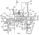
фиг.1 - вид сверху устройства для проверки тары согласно одному из предпочтительных вариантов осуществления данного изобретения;figure 1 is a top view of a device for checking containers according to one of the preferred embodiments of the present invention;
фиг.2 - вид с торца вертикальной проекции в направлении 2 на фиг.1;figure 2 is an end view of a vertical projection in
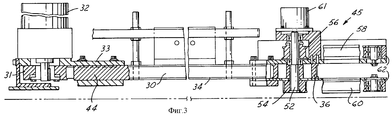
фиг.3 - сечение по линии З-З на фиг.2;figure 3 is a section along the line ZZ in figure 2;
фиг.4 и 5 - сечения по линиям 4-4 и 5-5 на фиг.1;4 and 5 are sections along lines 4-4 and 5-5 in figure 1;
фиг.6 - боковая вертикальная проекция в направлении 6 на фиг.1;FIG. 6 is a side elevational view in the direction 6 of FIG. 1;
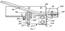
фиг.7 - фрагмент вида сверху в направлении 7 на фиг.6;Fig.7 is a fragment of a top view in
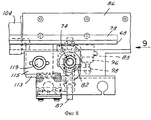
фиг.8 - фрагмент вида сверху в направлении 8 на фиг.6;Fig.8 is a fragment of a top view in
фиг.9 - вертикальная проекция с торца в направлении 9 на фиг.8;Fig.9 is a vertical projection from the end in the
фиг.10 и 10А - принципиальные схемы, иллюстрирующие примеры расположения проверочных оптических устройств относительно конвейера проверки;10 and 10A are schematic diagrams illustrating examples of the location of optical inspection devices relative to the verification pipeline;
фиг.11 - вид сверху устройства согласно второму варианту осуществления данного изобретения;11 is a top view of a device according to a second embodiment of the present invention;
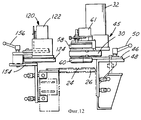
фиг.12 - вертикальная проекция с торца в направлении 12 на фиг.11;Fig.12 is a vertical projection from the end in the
фиг.13 - боковая вертикальная проекция в направлении 13 на фиг.11;Fig.13 is a side elevational view in the
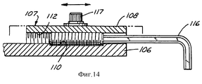
фиг.14 - фрагмент вертикальной проекции в направлении 14 на фиг.7;Fig.14 is a fragment of a vertical projection in the
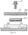
фиг.15 - перспективное изображение с пространственным разделением деталей механизма регулировки направляющей, изображаемой на фиг.14;Fig is a perspective image with a spatial separation of the parts of the adjustment mechanism of the guide depicted in Fig;
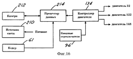
фиг.16 - функциональная блок-схема электронных устройств для работы проверочного устройства согласно данному изобретению; иFIG. 16 is a functional block diagram of electronic devices for operating a test device according to the present invention; FIG. and
фиг.17А, 17В и 17С - принципиальные схемы положений приводных ремней относительно тары разных размеров, данных в качестве примера.figa, 17B and 17C are schematic diagrams of the positions of the drive belts relative to containers of different sizes, given as an example.
фиг.1-10 и 14-16 изображают устройство 20 для проверки тары 22, перемещающейся на линейном конвейере 24, в соответствии с одним предпочтительным вариантом осуществления данного изобретения. Конвейер 24 может содержать сегментированный конвейер или бесконечный конвейерный ремень, например, расположенный с возможностью скольжения на конвейерной опоре 26, на которой установлено с возможностью съема и регулирования устройство 20. Конвейер 24 перемещает тару 22 последовательно в продольном направлении 28 на первой скорости конвейера. Устройство 20: 1) отклоняет тару 22 одну за другой с конвейера 24; 2) транспортирует тару с повышенной скоростью рядом с конвейером для увеличения интервала между тарой, при этом поворачивая тару вокруг ее оси; 3) во время транспортировки и поворачивания проверяет тару на наличие коммерческих изменений; и 4) отводит тару назад на конвейер 24, при этом прекращая поворачивание и уменьшая скорость, чтобы по существу согласовать ее со скоростью конвейера.1-10 and 14-16 depict a device 20 for checking
Устройство 20 содержит первый бесконечный приводной ремень 30, связанный с приводным двигателем 32 посредством звездочки 31 (фиг.3). Двигатель 32 устанавливают на опорной каретке 44 с помощью кронштейна 33. От звездочки 31 ремень 30 проходит вдоль каретки 44, вокруг компенсирующей износ пластины и шкива 36 и назад к звездочке 31. Впускной вылет 38 приводного ремня 30 расположен над конвейером 24 и находится относительно него под острым углом в направлении 28 движения конвейера, в результате чего тара 22 наталкивается на вылет ремня 38 последовательно при ее перемещении конвейером. Каретка имеет рычаги 46 кронштейна (фиг.1 и 2), посредством которых весь узел каретки 45 устанавливают на кронштейнах 48, прикрепляемых к опоре 26 конвейера (см. фиг.2). Рукоятки 50 устанавливают с возможностью съема, рычаги кронштейна каретки - на кронштейнах 48. Кронштейны 48 устанавливают вертикально относительно опоры 26 конвейера посредством вертикальных нажимных винтов 51, изображаемых на фиг.1. Прорези 49 в рычагах кронштейна 46 предусматривают поперечное регулирование узла каретки 45 относительно конвейера 24. Поэтому узел каретки 45 регулируется вертикально посредством нажимных винтов 51 и в поперечном направлении посредством рукояток 50 и прорезей 49. Натяжение в ремне 30 регулируют посредством прорезей 40 в кронштейне 42 двигателя. В том месте, где ремень 30 изменяет направление вдоль каретки, устанавливают компенсирующую износ пластину.The device 20 comprises a first
Как видно из фиг.1 и 3-5: первый приводной ремень 30 зацепляет шкив 36, который прикреплен к валу 52, вращающемуся в узле 45 каретки. Пара шкивов 54, 55 прикреплена к валу 52 на противоположных сторонах шкива 36. Пара расположенных через вертикальный интервал бесконечных разгрузочных приводных ремней 58, 60 соответственно связана со шкивами 56, 54 и проходит вокруг холостых шкивов 62, 64 и 35 в узле 45 каретки. Поэтому двигатель 32 приводит в движение ремень 30, который в свою очередь приводит в движение ремни 58, 60 через шкивы 36, 54 и 56. Передаточные отношения шкивов предпочтительно таковы, что ремни 58, 60 двигаются со скоростью, приближающейся к скорости конвейера 24, при этом ремень 30 идет со скоростью, которая более чем в два раза превышает скорость конвейера. Узел разгрузочного ремня вместе с двигателем 32 и ремнем 30 опирается на каретку 44 и таким образом составляет часть узла 45 каретки. Вал 52 связан с кодером 61, который в свою очередь соединен с электронными средствами управления (фиг.16), обеспечивающими индикацию работы и скорости ремня. Шкивы 35, 64 коаксиально установлены на валу 59 (фиг.4) посредством соответствующих подшипников. Вал 59 установлен на узле 45 каретки.As can be seen from figures 1 and 3-5: the
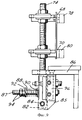
Напротив приводного ремня 30, содержащего подающий вылет 38, в варианте осуществления согласно фиг.1-10 находится узел 66 направляющей упора. Обращаясь к фиг.1 и 6-9: узел 66 направляющей упора содержит пару удлиненных направляющих 68, 70, установленных с вертикальным интервалом между ними на паре имеющих между собой продольный интервал установочных стоек 72, 74 направляющей. Каждая направляющая 68, 70 имеет расположенный под углом подающий вылет 76, который приблизительно параллелен в сборе с подающим вылетом 38 ремня 30 (фиг.1). В предпочтительном варианте осуществления данного изобретения подающий вылет каждой направляющей 68, 70 отклонен приблизительно на один градус от противолежащего подающего вылета 38 ремня 30 для улучшения захвата двигающейся к сужению тары. Удлиненный корпус каждой направляющей 68, 70 является линейным и параллельным противоположному удлиненному вылету ремня 30. Каждая направляющая 68, 70 имеет облицовочный слой 18, 80 из эластомерного материала, такого как пенорезина, для зацепления тарой 22. Стойки 72, 74 имеют резьбу, а направляющие 68, 70 устанавливаются на них вертикально с возможностью регулирования согласно фиг.9. Нижний конец каждой стойки 72, 74 прикреплен к колодке 82, которая выполнена с возможностью поворота на горизонтальном штифте 84, находящемся на колодке 85, расположенной под кареткой 86. Палец 87 проходит горизонтально от каждой колодки 85 через соответствующую колодку 82, а спиральная пружина 88 захватывается в сжатом состоянии между прокладкой 90, примыкающей к каждой колодке 82, и прокладкой 92 и парой гаек 94 на каждом пальце 87. Пружины 88 таким образом придвигают колодки 82, стойки 72, 74 и направляющие 68, 70 вправо на фиг.9, и в сторону ремня 30 на фиг.1. Направляющие 68, 70 и стойки 72, 74 выполнены с возможностью поворота вокруг шпилек 84 в сторону от ремня 30, преодолевая усилие пружин 88. Усилие пружин 88, сопротивляющееся таковому поворотному движению, можно отрегулировать посредством гаек 94. Концевой выключатель 96 находится на каждой колодке 85 в прилегании к каждой стойке 72, 74 направляющей. Каждый концевой выключатель 96 связан с прилегающей поворотной колодкой 82 посредством поперечины 98. Поперечины 98 обычно контактируют и нажимают на исполнительный механизм каждого выключателя 96. В том случае, если направляющие и установочные стойки поворачиваются в сторону от приводного ремня 30, преодолевая усилия пружин 88, на достаточное расстояние, тогда исполнительные механизмы переключателей 96 высвобождаются, и переключатели соответственно изменяют свое состояние.Opposite the
Весь узел направляющей 66 устанавливают на каретке 86. Компенсирующую износ пластину 104 также устанавливают на каретке 86 в положении под направляющими 68, 70. Удлиненная прорезь 105 (фиг.1 и 10) образована краями компенсирующей износ пластины 104 и конвейером 24 согласно фиг.1. Направляющие 68, 70 отдельно вертикально регулируются на стойках 72, 74 и отдельно устанавливаются горизонтально с возможностью регулирования на каретке 86 посредством механизма 107 согласно фиг.1, 6, 7, 14 и 15. В прилегании к подающему вылету каждой направляющей 68, 70 нижнюю пластину 106 прикрепляют к каждой направляющей, и она проходит в поперечном направлении в сторону от конвейера 24. На каждой нижней пластине 106 устанавливается с возможностью скольжения верхняя пластина 108, которая проходит в продольном направлении от нижней пластины 106 к установочной стойке 72. Противоположные гайки устанавливают с возможностью регулирования, верхние пластины 108 на установочной стойке 72. Каждая нижняя пластина 106 имеет карман 110, и каждая верхняя пластина 108 имеет частично цилиндрическое отверстие со сформированной в ней резьбой 112. Установочный винт 114 расположен в кармане 110 каждой пластины 106 в резьбовом зацеплении с резьбой 112 на соответствующей пластине 108. Поэтому гаечный ключ 116 (фиг.14) или другой соответствующий инструмент может быть зацеплен с винтом 114 для регулирования положения пластины 106 и тем самым находящейся на ней направляющей относительно пластины 108 и установочной стойки 72. Пара винтов 117 проходит через пластину 108 в пластину 106 для фиксирования пластин и направляющих в отрегулированном положении. Конечные по ходу движения концы направляющих 68, 70 устанавливают продольно с возможностью регулирования относительно стойки 74 посредством пластин 113, 115 и винта 119 (фиг.1 и 8). Поэтому находящиеся под углом подающие вылеты 76 направляющих 68, 70 можно регулировать в продольном направлении относительно подающего вылета 38 ремня 30, при этом основные части ремня 30 и направляющих 68, 70 остаются параллельными друг другу на конвейере 24 и компенсирующей износ пластине 104. Такое регулирование направляющих допускает работу с тарой разного диаметра, с разным фрикционным зацеплением между подающим вылетом 38 ремня 30 и противоположными эластомерными поверхностями направляющих. Поперечное положение направляющих можно регулировать посредством прорезей в пластинах 108, 115 вокруг стоек 72, 74, а вертикальное положение направляющих можно регулировать посредством резьбовых стоек 72, 74 в соответствии с изложенным выше (см. фиг.9).The
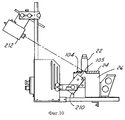
Фиг.10 иллюстрирует расположение источника 210 света проверки и камеры проверки 212 относительно друг друга и относительно компенсирующей износ пластины 104 и конвейера 24. При отводе тары 22 вылетом 38 подающего ремня и подающими вылетами 76 направляющей в поперечном направлении от конвейера 24, чтобы ее затем транспортировать конвейером 24 и компенсирующей износ пластиной 104, скорость продольного движения тары увеличивают. Предпочтительно, чтобы скорость ремня 30 приблизительно превышала в 2,2 раза скорость конвейера 24, что увеличивает скорость тары, которая проходит через станцию проверки со скоростью, превышающей скорость конвейера приблизительно в 1,1 раза. Это небольшое повышение скорости тары обеспечивает создание небольшого разделяющего промежутка между тарой, предпочтительно порядка половины дюйма (около 1,2 см), даже если она тесно составлена на входе в станцию проверки. При этом зацепление вращением между тарой 22 и направляющими 68, 70 вместе с приводным движением ремня 30 поворачивает тару вокруг ее оси при продвижении тары последовательно через прорезь 105. Источник света 210 размещен под некоторым углом, чтобы проецировать линейный луч света через прорезь 105 на дно следующей идущей последовательно тары во время ее прохождения над прорезью. Камера 212 установлена над и сбоку от конвейера 24 и компенсирующей износ пластины 104 и имеет поле обзора, проходящее вдоль прорези 105 между компенсирующей износ пластиной и конвейером. Таким образом энергия света преломляется и/или отражается от каждой единицы тары 22 последовательно в камеру 212. Источник света 210 соединен с источником электропитания. Камера 212 содержит процессор обработки данных 214 (фиг.16) для анализа световой энергии, принимаемой камерой 212, и получения соответствующей информации, указывающей на коммерческие изменения в таре. В этом отношении действие источника света 210, камеры 212 и процессора данных 214 предпочтительно соответствует патенту США № 4874940.Figure 10 illustrates the location of the
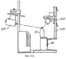
Фиг.10А изображает другой вариант проверочной конфигурации камеры 212 и источника света 210. В фиг.10А источник света 210 установлен на кронштейне 216 над опорой конвейера 26 и под углом в направлении вниз, чтобы направлять световую энергию на поверхность тары 22 по мере ее прохождения через станцию проверки. Отраженная световая энергия падает на камеру 212 для обнаружения коммерческих изменений. Для проверки тары при разных типах коммерческих изменений при прохождении тары через станцию проверки посредством устройства данного изобретения могут быть осуществлены разнообразные другие ориентации и конфигурации источника света/камеры.Fig. 10A depicts another embodiment of the test configuration of the
Узел привода разгрузки 120 (фиг.1, 2 и 6) установлен в прилегании к конечному по ходу движения концу направляющих 68, 70 (относительно направления движения конвейера 24). Узел привода разгрузки 120 содержит двигатель привода 122, связанный с бесконечным приводным ремнем 124. Приводной ремень 124 проходит вокруг находящихся друг от друга на некотором интервале шкивов, установленных на каретке 126 таким образом, что один удлиненный вылет ремня 124 параллелен находящимся под углом вылетам разгрузочных приводных ремней 58, 60. Каретка 126 установлена с возможностью съема на кронштейне 130 и выполнена с возможностью поперечного позиционирования относительно него посредством регулирующих рукояток 131. Вертикальная часть кронштейна 130 имеет вертикально ориентированные прорези-отверстия, с помощью которых кронштейн вертикально монтируется с возможностью регулирования рукоятками 132 на опоре конвейера 26. Таким образом разгрузочный привод 120 выполнен с возможностью регулирования вертикально и поперечно относительно опоры конвейера и также выполнен с возможностью продольного регулирования посредством прорезей-отверстий в узле каретки. Двигатель 122 имеет такую скорость, что скорость ремня 124 согласуется со скоростью ремней 58, 60 и по существу согласуется со скоростью конвейера 24. Управление двигателями 32, 122 осуществляется контроллером двигателя 134 (фиг.16), которым управляют с помощью концевых выключателей 96 направляющей. То есть если концевые выключатели 96 направляющей указывают поворотное движение направляющих в сторону от приводного ремня 30, то контроллер 134 выключает двигатели 32, 122, по существу останавливая станцию проверки. Поэтому станция проверки останавливается в случае поворота направляющих по причине затора тары между направляющими и приводным ремнем, или если направляющие поворачиваются относительно нормального положения вручную оператором для осмотра или для других целей.The unloading drive unit 120 (FIGS. 1, 2, and 6) is mounted adjacent to the end along the direction of the end of the
В работе: тара 22 направляется последовательно и вводится конвейером 24 в непосредственный контакт с подающим вылетом 38 приводного ремня 30. Приводной ремень немного увеличивает продольную скорость тары, при этом отводя тару последовательно в поперечном направлении частично с конвейера. Тару упруго захватывают между приводным ремнем 30 и направляющими 68, 70 перед тем, как тара частично покидает конвейер 24 благодаря находящемуся под углом вылету 76 каждой направляющей 68, 70. Опорная каретка 44 предотвращает отклонение ремня 30 в сторону от направляющих 68, 70. Когда тара захвачена таким образом, все еще находясь на конвейере, неустойчивость тары из-за неровного движения, столкновений или падения значительно снижается. Тару, захваченную между ремнем 30 и направляющими 68, 70, продвигают в продольном направлении на увеличенной скорости через станцию проверки, и при этом она поворачивается вокруг своей оси при прохождении через прорезь проверки 105. Узел каретки 45 и узел направляющей 66 регулируют в поперечном направлении относительно конвейера 24, в результате чего тара 22 находится в отцентрованном положении над прорезью 105. После транспортирования тары над прорезью проверки ее вводят в положение между разгрузочными ремнями 58, 60 на узле 45 и ремнем 124 на разгрузочном приводе 120. Эти ремни предпочтительно приводят в действие по существу на одинаковой скорости, которая по существу та же, что и продольная скорость конвейера 24, в результате чего тара уже не поворачивается вокруг своей оси, а отводится последовательно назад на конвейер 24. Этот захват тары между противоположными разгрузочными приводными ремнями сводит к минимуму неустойчивость тары во время обратного переноса ее на конвейер 24.In the work: the
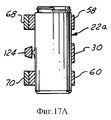
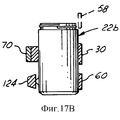
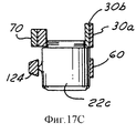
Фиг.17А иллюстрирует отрегулированные положения для направляющих 68, 70, разгрузочных ремней 58, 60, 124 и приводного ремня 30 относительно корпуса типов тары 22а, такой, как длинный сосуд или бутылка с длинным горлышком, имеющие удлиненный по оси корпус. Направляющие 68, 70 регулируют для зацепления отличающихся друг от друга по вертикали частей корпуса тары, при этом приводной ремень 30 зацепляет центральную часть корпуса тары. Усилия уравновешивают, чтобы не опрокинуть тару. Разгрузочный ремень 124 позиционируют таким образом, чтобы зацепить центральную часть корпуса; при этом противоположные разгрузочные ремни 58, 60 зацепляют верхнюю и нижнюю части корпуса тары, чтобы предотвратить опрокидывание тары. Таким образом, усилия, прилагаемые к таре 22а во время подачи, при продольном движении для проверки и подачи, уравновешиваются относительно корпуса тары. Фиг.17В иллюстрирует положение ремня и направляющей для более короткой тары 226. Напротив приводного ремня 30 применяют единую направляющую 70, а разгрузочный ремень 124 противоположен ремню 60 в поперечном направлении. Фиг.17С иллюстрирует компоновку для работы, например, с тарой детского питания 22с. В этом случае также разгрузочные ремни 124, 60 противоположны друг другу в нижней части тары. Направляющая 70 и подающий приводной ремень 30а зацепляют поверхность тары 22с. Приводной ремень 30а имеет амортизирующий слой 306 для улучшения зацепления с поверхностью тары. Например, узел разгрузочного привода 122 иллюстрирован на фиг.2 в положении, соответствующем фиг.17В и 17С, и на фиг.6 - в положении, соответствующем фиг.17А.FIG. 17A illustrates adjusted positions for
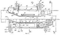
Фиг.11-13 иллюстрируют модифицированное устройство 140 в соответствии с осуществлением данного изобретения, которое особо целесообразно для применения с такой крупной тарой, как сосуды. Ссылочные номера, идентичные номерам в фиг.1-10, обозначают те же детали или компоненты. Узел каретки 45, включая приводной ремень 30 и двигатель 32 на каретке 44, тот же, что и в предыдущем осуществлении, но установлен с возможностью регулирования относительно конвейера 24 дальше от прорези проверки 105 согласно фиг.11. В этом случае также цель этого регулирования заключается в том, чтобы поместить диаметр тары 142 над прорезью 105. Противолежащий узел упора 144 содержит приводной ремень 146, который проходит вокруг пары отделяемых друг от друга некоторым интервалом шкивов 145, один из которых связан с приводным двигателем 148 (фиг.11-13 и 16). Ремень 146 имеет продольный вылет напротив продольного вылета ремня 30 и отделен от него интервалом на противоположной стороне прорези проверки 105. Ремень 146 приводят в действие двигателем 148 в направлении, противоположном направлению ремня 30. Расположенная под углом направляющая 150 проходит против хода движения от ремня 146 под некоторым углом, противоположным подающему вылету 38 ремня 30. На конечном по ходу движения конце узла упора 144 находится узел 120 разгрузочного привода, идентичный описываемому выше. Весь узел упора 144, включая приводной ремень 146 с соответствующим двигателем 148, находящуюся под углом направляющую 150 и подающий привод 120, установлен на каретке 152, которая установлена на опоре конвейера 26 посредством кронштейнов 154 и рукояток 100. Более крупная тара 142 из-за своего большего диаметра относительно осевой длины имеет меньшую устойчивость во время подачи и разгрузки с конвейера 24. Но для тары с большим диаметром скорость поворачивания должна быть увеличена во время прохождения через отверстие проверки 105, чтобы во время проверки тара поворачивалась по меньшей мере на 360°. Скорости ремней 30 и 146 регулируют для увеличения скорости поворачивания тары и для небольшого увеличения скорости движения в продольном направлении, чтобы обеспечить разрыв (предпочтительно по меньшей мере в половину дюйма (около 1,2 см)) между тарой при пересечении ею станции проверки.11-13 illustrate a modified
Выше раскрыты два осуществления данного изобретения, которые полностью соответствуют сформулированным выше задачам и целям. Подача и разгрузка тары с и на линейный конвейер осуществляются с помощью двигателей привода; при этом тару захватывают между противоположными элементами, что намного уменьшает неустойчивость тары при переходе с и на конвейер и в свою очередь уменьшает вероятность того, что тара опрокинется на конвейере или в устройстве проверки. В осуществлении согласно фиг.1-10 подпружиненные направляющие с концевыми выключателями образуют средство для быстрого выборочного удаления изделия из устройства проверки в случае затора или по какой-либо другой причине и автоматического прекращения работы устройства проверки в случае неправильной подачи тары. Направляющие выполнены с возможностью регулирования во время работы в продольном направлении конвейера для вмещения тары разного размера и в разных состояниях. Двойной ременной привод предусматривают для использования с изделиями крупного диаметра без какого-либо ущерба устойчивости или другими преимуществами данного изобретения.The above disclosed two implementations of the present invention, which are fully consistent with the above objectives and objectives. The supply and unloading of containers from and to the linear conveyor is carried out using drive motors; in this case, the container is seized between opposite elements, which greatly reduces the instability of the container during the transition from and to the conveyor and, in turn, reduces the likelihood that the container will tip over on the conveyor or in the checking device. In the embodiment of FIGS. 1-10, spring-loaded rails with limit switches form a means for quickly selectively removing an article from the inspection device in the event of a jam or for some other reason and automatically stopping the operation of the inspection device in the event of improper supply of containers. The guides are made with the possibility of regulation during operation in the longitudinal direction of the conveyor to accommodate containers of different sizes and in different conditions. A dual belt drive is provided for use with large diameter products without any damage to stability or other advantages of the present invention.
Для удобства сборки на соответствующие каретки устанавливают разные приводы тары и механизмы упора, которые можно удобно адаптировать для имеющихся конвейерных систем.For ease of assembly, different tare drives and stop mechanisms are installed on the respective carriages, which can be conveniently adapted for existing conveyor systems.
Claims (26)
Applications Claiming Priority (2)
| Application Number | Priority Date | Filing Date | Title |
|---|---|---|---|
| US09/170,709 | 1998-10-13 | ||
| US09/170,709 US6172355B1 (en) | 1998-10-13 | 1998-10-13 | In-line inspection of containers |
Publications (2)
| Publication Number | Publication Date |
|---|---|
| RU99121409A RU99121409A (en) | 2001-07-27 |
| RU2230697C2 true RU2230697C2 (en) | 2004-06-20 |
Family
ID=22620947
Family Applications (1)
| Application Number | Title | Priority Date | Filing Date |
|---|---|---|---|
| RU99121409/03A RU2230697C2 (en) | 1998-10-13 | 1999-10-12 | Device for and method of checking containers on conveyor line |
Country Status (22)
| Country | Link |
|---|---|
| US (1) | US6172355B1 (en) |
| EP (1) | EP0994344B9 (en) |
| JP (1) | JP3585787B2 (en) |
| CN (1) | CN1183383C (en) |
| AR (1) | AR018963A1 (en) |
| AT (1) | ATE406570T1 (en) |
| AU (1) | AU752455C (en) |
| BR (1) | BR9904717B1 (en) |
| CA (1) | CA2284347C (en) |
| CO (1) | CO5021145A1 (en) |
| CZ (1) | CZ298841B6 (en) |
| DE (1) | DE69939417D1 (en) |
| DK (1) | DK0994344T3 (en) |
| EE (1) | EE04715B1 (en) |
| ES (1) | ES2313764T3 (en) |
| HU (1) | HU228729B1 (en) |
| PE (1) | PE20001206A1 (en) |
| PL (1) | PL189620B1 (en) |
| PT (1) | PT994344E (en) |
| RU (1) | RU2230697C2 (en) |
| UA (1) | UA61945C2 (en) |
| ZA (1) | ZA996378B (en) |
Families Citing this family (20)
| Publication number | Priority date | Publication date | Assignee | Title |
|---|---|---|---|---|
| US6172355B1 (en) * | 1998-10-13 | 2001-01-09 | Owens-Brockway Glass Container Inc. | In-line inspection of containers |
| US6693275B1 (en) * | 2000-03-23 | 2004-02-17 | Plastipak Packaging, Inc. | Method and apparatus for inspecting blow molded containers |
| FR2816296B1 (en) * | 2000-11-09 | 2002-12-20 | Commissariat Energie Atomique | CONTINUOUSLY SCROLLING OBJECT DEVICE WITH REVOLUTION SYMMETRY - APPLICATION TO VISUAL INSPECTION AND INSPECTION |
| US6806459B1 (en) | 2001-08-30 | 2004-10-19 | Owens-Brockway Glass Container Inc. | Measurement of transparent container sidewall thickness |
| US20050077217A1 (en) * | 2003-03-28 | 2005-04-14 | Hillerich Thomas A. | Carrier for mail and/or the like thin objects |
| US20060000752A1 (en) * | 2003-03-28 | 2006-01-05 | Northrop Grumman Corporation | Stack correction system and method |
| US7195236B2 (en) * | 2003-03-28 | 2007-03-27 | Northrop Grumman Corporation | Automated induction systems and methods for mail and/or other objects |
| WO2004101401A2 (en) * | 2003-05-13 | 2004-11-25 | Northrop Grumman Corporation | Enhanced object-feeder pre-processing system |
| US7010863B1 (en) * | 2004-01-26 | 2006-03-14 | Owens-Brockway Glass Container Inc. | Optical inspection apparatus and method for inspecting container lean |
| US7438192B1 (en) | 2004-05-28 | 2008-10-21 | Owens-Brockway Glass Container Inc. | Electronic control system for container indexing and inspection apparatus |
| US20060099065A1 (en) * | 2004-08-27 | 2006-05-11 | Northrop Grumman Corporation | Preparation operator flex-station for carrier preparation |
| EP1794073B1 (en) * | 2004-09-24 | 2014-03-05 | Northrop Grumman Systems Corporation | Anti-toppling device for mail and/or the like |
| DE102007025524B4 (en) * | 2007-05-31 | 2010-07-29 | Khs Ag | Opto-electrical detection system |
| US7766171B2 (en) * | 2008-02-28 | 2010-08-03 | Northrop Grumman Systems Corporation | Rigid storage tray for flat and letter mail |
| US8429989B2 (en) * | 2008-10-18 | 2013-04-30 | Emhart Glass S.A. | Modular apparatus and method for rotating glass containers and the like |
| CN101793842B (en) * | 2010-03-09 | 2012-06-06 | 长沙图创机电科技有限公司 | Intelligent on-line visual detection robot for visible foreign matters in bottled liquid |
| CN101852743A (en) * | 2010-06-07 | 2010-10-06 | 湖南大学 | Bottle-rubbing device used for visual inspection of visible foreign substances in bottled liquid |
| CN104698006B (en) * | 2015-02-11 | 2017-05-10 | 湖南正中制药机械有限公司 | Machine for automatically checking foreign bodies in soft bag preparation drugs |
| US10099862B2 (en) | 2017-03-15 | 2018-10-16 | Owens-Brockway Glass Container Inc. | Container conveyor apparatus with an adjustable railing |
| CN113682779A (en) * | 2021-08-25 | 2021-11-23 | 合肥友高物联网标识设备有限公司 | Be used for high-speed collection system of bottled product two-dimensional code |
Family Cites Families (21)
| Publication number | Priority date | Publication date | Assignee | Title |
|---|---|---|---|---|
| US2446377A (en) | 1944-08-29 | 1948-08-03 | Pabst Brewing Co | Apparatus for inspecting moving transparent objects |
| US2825442A (en) | 1955-03-16 | 1958-03-04 | Meyer Geo J Mfg Co | Article orienting mechanism for conveyors |
| US2863355A (en) | 1955-03-29 | 1958-12-09 | Harold A Ledingham | Optical inspection units for bottled goods |
| US3101848A (en) * | 1961-03-15 | 1963-08-27 | Owens Illinois Glass Co | Container handling apparatus |
| US3428174A (en) | 1966-09-26 | 1969-02-18 | Emhart Corp | Apparatus and method for handling glassware for inspection or the like |
| US3415350A (en) | 1966-10-24 | 1968-12-10 | Fmc Corp | Article orienting apparatus |
| CH548599A (en) * | 1972-01-19 | 1974-04-30 | Emhart Zuerich Sa | Crack testing station for the sorting line of a plant for the production of glass containers. |
| US4021122A (en) | 1973-01-02 | 1977-05-03 | Emhart Zurich S.A. | Glass container inspection machine |
| US3866739A (en) | 1973-02-28 | 1975-02-18 | Standard Metal Products | Free flow device for container unscramblers |
| US3901381A (en) * | 1973-10-10 | 1975-08-26 | Ball Brothers Service Corp | Automatic ware handler |
| US4378495A (en) * | 1980-11-07 | 1983-03-29 | Owens-Illinois, Inc. | Method and apparatus for setup of inspection devices for glass bottles |
| US4378494A (en) * | 1980-11-07 | 1983-03-29 | Owens-Illinois, Inc. | Apparatus and method for detecting defects in glass bottles using event proximity |
| US4464884A (en) | 1981-06-19 | 1984-08-14 | Owens-Illinois, Inc. | Adjustable bottle conveying apparatus |
| US4601395A (en) * | 1984-04-23 | 1986-07-22 | Owens-Illinois, Inc. | Inspecting and sorting of glass containers |
| US4874940A (en) | 1988-01-11 | 1989-10-17 | Brockway, Inc. (N.Y.) | Method and apparatus for inspection of a transparent container |
| US4914289A (en) | 1988-10-26 | 1990-04-03 | Inex-Vistech Technologies Incorporated | Article inspection system for analyzing end and adjacent sides |
| FR2642164B1 (en) | 1989-01-26 | 1991-04-12 | Saint Gobain Cinematique Contr | CHECKING HIGH-RATE OBJECTS |
| US5097216A (en) | 1990-10-09 | 1992-03-17 | Agr International, Inc. | Apparatus for inspecting the wall thickness of a container and corresponding method |
| US5422476A (en) | 1993-09-15 | 1995-06-06 | Emhart Glass Machinery Investments Inc. | Glass container inspection machine |
| US5573103A (en) | 1994-10-24 | 1996-11-12 | Agr International, Inc. | Speed adjusting apparatus for containers |
| US6172355B1 (en) * | 1998-10-13 | 2001-01-09 | Owens-Brockway Glass Container Inc. | In-line inspection of containers |
-
1998
- 1998-10-13 US US09/170,709 patent/US6172355B1/en not_active Expired - Lifetime
-
1999
- 1999-10-01 CA CA002284347A patent/CA2284347C/en not_active Expired - Fee Related
- 1999-10-01 HU HU9903326A patent/HU228729B1/en not_active IP Right Cessation
- 1999-10-06 AU AU53488/99A patent/AU752455C/en not_active Ceased
- 1999-10-08 ZA ZA9906378A patent/ZA996378B/en unknown
- 1999-10-09 DE DE69939417T patent/DE69939417D1/en not_active Expired - Fee Related
- 1999-10-09 PT PT99120223T patent/PT994344E/en unknown
- 1999-10-09 DK DK99120223T patent/DK0994344T3/en active
- 1999-10-09 EP EP99120223A patent/EP0994344B9/en not_active Expired - Lifetime
- 1999-10-09 ES ES99120223T patent/ES2313764T3/en not_active Expired - Lifetime
- 1999-10-09 AT AT99120223T patent/ATE406570T1/en not_active IP Right Cessation
- 1999-10-11 CO CO99064470A patent/CO5021145A1/en unknown
- 1999-10-11 PE PE1999001024A patent/PE20001206A1/en not_active Application Discontinuation
- 1999-10-11 CZ CZ0359099A patent/CZ298841B6/en not_active IP Right Cessation
- 1999-10-12 EE EEP199900366A patent/EE04715B1/en unknown
- 1999-10-12 RU RU99121409/03A patent/RU2230697C2/en not_active IP Right Cessation
- 1999-10-12 PL PL99335955A patent/PL189620B1/en unknown
- 1999-10-12 UA UA99105576A patent/UA61945C2/en unknown
- 1999-10-12 AR ARP990105148A patent/AR018963A1/en active IP Right Grant
- 1999-10-13 CN CNB991252292A patent/CN1183383C/en not_active Expired - Fee Related
- 1999-10-13 JP JP29087699A patent/JP3585787B2/en not_active Expired - Fee Related
- 1999-10-13 BR BRPI9904717-9A patent/BR9904717B1/en not_active IP Right Cessation
Also Published As
| Publication number | Publication date |
|---|---|
| DK0994344T3 (en) | 2009-01-12 |
| BR9904717B1 (en) | 2012-07-10 |
| US6172355B1 (en) | 2001-01-09 |
| CA2284347A1 (en) | 2000-04-13 |
| HU9903326D0 (en) | 1999-12-28 |
| AU752455B2 (en) | 2002-09-19 |
| CZ359099A3 (en) | 2000-06-14 |
| PL335955A1 (en) | 2000-04-25 |
| EP0994344B9 (en) | 2009-04-01 |
| PT994344E (en) | 2008-12-05 |
| AR018963A1 (en) | 2001-12-12 |
| HUP9903326A3 (en) | 2002-10-28 |
| PE20001206A1 (en) | 2000-11-07 |
| CN1183383C (en) | 2005-01-05 |
| ZA996378B (en) | 2000-04-12 |
| EE9900366A (en) | 2000-06-15 |
| CO5021145A1 (en) | 2001-03-27 |
| AU5348899A (en) | 2000-04-20 |
| PL189620B1 (en) | 2005-08-31 |
| EP0994344B1 (en) | 2008-08-27 |
| HUP9903326A2 (en) | 2000-06-28 |
| EP0994344A1 (en) | 2000-04-19 |
| CN1257200A (en) | 2000-06-21 |
| CZ298841B6 (en) | 2008-02-20 |
| JP2000121575A (en) | 2000-04-28 |
| AU752455C (en) | 2003-06-12 |
| ES2313764T3 (en) | 2009-03-01 |
| BR9904717A (en) | 2000-10-17 |
| ATE406570T1 (en) | 2008-09-15 |
| JP3585787B2 (en) | 2004-11-04 |
| DE69939417D1 (en) | 2008-10-09 |
| UA61945C2 (en) | 2003-12-15 |
| HU228729B1 (en) | 2013-05-28 |
| CA2284347C (en) | 2005-12-13 |
| EE04715B1 (en) | 2006-10-16 |
Similar Documents
| Publication | Publication Date | Title |
|---|---|---|
| RU2230697C2 (en) | Device for and method of checking containers on conveyor line | |
| US4676361A (en) | Troughing conveyors for carton or bag orienting and conveying | |
| JP6916237B2 (en) | Sorting conveyor with article removal device | |
| KR960704697A (en) | CARTON FEEDER ASSEMBLY | |
| AU2006330088A1 (en) | Automatic carton magazine loading system | |
| US5348139A (en) | Counter-balanced pressure sensor for conveyor accumulation zone | |
| US4850470A (en) | Apparatus for transferring elongated sample tube holders to and from workstations | |
| US5211529A (en) | Horizontal staging hopper | |
| US2858929A (en) | Bottle discharger | |
| US4760909A (en) | Suction diverter | |
| CN113060499A (en) | But height-adjusting's goods conveyor | |
| US3831737A (en) | Decorator loading apparatus | |
| CN113911727B (en) | PCB (printed circuit board) developing processing system | |
| US4928453A (en) | Apparatus for transferring elongated sample tube holders to and from workstations | |
| CN212354667U (en) | Self-rotating bottle rotating machine | |
| JPH0741980B2 (en) | Goods delivery device | |
| US6039169A (en) | Multilevel storage device for containers, in particular CD cases | |
| JPH11199040A (en) | Container conveying device | |
| CN115420751B (en) | Automatic inspection device for foreign matters in oral solution and production process | |
| US20070102262A1 (en) | Continuous motion article diverting system | |
| CN114161619B (en) | Feeding control system for waste plastic bucket treatment line | |
| JP4367680B2 (en) | Cutting device | |
| KR20020075023A (en) | Apparatus for collecting transporting goods on belt conveyor | |
| JPH02270716A (en) | Method of holding article to be conveyed and device therefor | |
| CN115608628A (en) | Screen detection system |
Legal Events
| Date | Code | Title | Description |
|---|---|---|---|
| MM4A | The patent is invalid due to non-payment of fees |
Effective date: 20091013 |