RU2229338C2 - Scouring machine - Google Patents
Scouring machine Download PDFInfo
- Publication number
- RU2229338C2 RU2229338C2 RU2001112753/12A RU2001112753A RU2229338C2 RU 2229338 C2 RU2229338 C2 RU 2229338C2 RU 2001112753/12 A RU2001112753/12 A RU 2001112753/12A RU 2001112753 A RU2001112753 A RU 2001112753A RU 2229338 C2 RU2229338 C2 RU 2229338C2
- Authority
- RU
- Russia
- Prior art keywords
- abrasive
- cylinder
- bars
- working
- friction
- Prior art date
Links
Images
Abstract
Description
Изобретение относится к технике мукомольно-крупяного производства, в частности к устройствам для шелушения сырья при изготовлении круп из ячменя, проса, гороха, кукурузы, сои, сорго, и предназначено для использования на крупозаводах и в подготовительных отделениях мельниц.The invention relates to techniques for flour and cereal production, in particular to devices for peeling raw materials in the manufacture of cereals from barley, millet, peas, corn, soybeans, sorghum, and is intended for use in cereals and in the preparatory departments of mills.
Известно устройство для шелушения пленчатого крупяного зерна, содержащее корпус, размещенный в нем и соединенный с приводом вертикальный вал с жестко закрепленными на нем абразивными дисками, перфорированный цилиндр, размещенный в корпусе концентрично валу с дисками, приемное и выпускное приспособления, размещенные соответственно в верхней и нижней частях корпуса. Зерно поступает в пространство между абразивными дисками и перфорированным цилиндром, где подвергается продолжительному трению о диски и перфорированный цилиндр, [М.Е.Гинзбург “Технология крупяного производства”, 1969, с.64] [1].A device for peeling of film-like cereal grain is known, comprising a housing located therein and connected to a drive with a vertical shaft with abrasive disks rigidly fixed thereon, a perforated cylinder placed concentrically in the housing with a shaft with disks, intake and exhaust devices located respectively in the upper and lower parts of the body. The grain enters the space between the abrasive disks and the perforated cylinder, where it undergoes continuous friction against the disks and the perforated cylinder, [M.E. Ginzburg “Technology of cereal production”, 1969, p.64] [1].
Недостатком этого устройства является низкая эффективность шелушения, обусловленная недостаточно интенсивным воздействием абразивных дисков на зерно, невозможность компенсации износа дисков, приводящая к дополнительному ухудшению качества готовой продукции.The disadvantage of this device is the low efficiency of peeling, due to the insufficiently intense impact of abrasive discs on grain, the inability to compensate for wear of the discs, leading to an additional deterioration in the quality of the finished product.
Наиболее близкой к предлагаемому по технической сущности является шелушильная машина, снабженная механизмом регулирования зазора между абразивной поверхностью и перфорированным цилиндром, абразивные органы выполнены в виде брусков трапецеидальной формы с большим основанием, обращенным к оси вала, и меньшим основанием, выполненным криволинейным. [СССР, а.с. 1329817, В 02 В 3/00] [2].Closest to the proposed technical essence is a peeling machine equipped with a mechanism for regulating the gap between the abrasive surface and the perforated cylinder, the abrasive bodies are made in the form of trapezoidal bars with a large base facing the axis of the shaft and a smaller base made curved. [USSR, A.S. 1329817, 02 V 3/00] [2].
Недостатком такого устройства является сравнительно низкая эффективность шелушения сырья.The disadvantage of this device is the relatively low efficiency of peeling of raw materials.
Целью изобретения является повышение эффективности работы шелушильной машины.The aim of the invention is to increase the efficiency of the peeling machine.
Цель достигается следующим образом: в машине, содержащей корпус, приемный патрубок, вертикально расположенный вал с радиально установленными на нем абразивными рабочими органами, выполненными в виде брусков, расположенных равномерно вокруг вала с возможностью радиального перемещения, закрепленный на корпусе и охватывающий рабочие органы цилиндр, отводящий и выходной патрубки, механизм регулирования зазора между абразивной поверхностью и цилиндром, рабочие органы повернуты на острый угол α1, образованный касательной линией и рабочей стороной абразивного органа, а цилиндр снабжен чередующимися фрикционными брусками и перфорированными вставками, при этом фрикционные бруски установлены под тупым углом α2, образованным касательной линией и рабочей стороной фрикционного бруска с возможностью его радиального перемещения.The goal is achieved as follows: in a machine containing a housing, a receiving pipe, a vertically arranged shaft with abrasive working bodies radially mounted on it, made in the form of bars arranged uniformly around the shaft with the possibility of radial movement, mounted on the housing and covering the working bodies of the cylinder, and outlet pipe, a mechanism for adjusting the gap between the abrasive surface and the cylinder, the working bodies are turned through an acute angle α1 formed by the tangent line and the working thoron abrasive body and the cylinder is provided with a friction alternating bars and perforated inserts, with friction bars set at an obtuse angle α2, formed by the tangent line and the working side of the friction bar with the possibility of radial displacement.
Технический результат достигается путем интенсификации воздействия абразивных брусков на зерно за счет образующихся сжимающе-истирающих усилий в клиновидном зазоре. Клиновидный зазор формируется рабочими поверхностями фрикционного бруска и абразивного рабочего органа в момент их встречного относительного движения. Переменные по величине воздействия, многократно прикладываемые к зерну, приводят к разрушению оболочки, что облегчает ее последующее отделение от ядра.The technical result is achieved by intensifying the effect of abrasive bars on the grain due to the resulting compressive-abrasive forces in the wedge-shaped gap. The wedge-shaped gap is formed by the working surfaces of the friction bar and the abrasive working body at the moment of their oncoming relative motion. Variables in magnitude of exposure, repeatedly applied to the grain, lead to the destruction of the shell, which facilitates its subsequent separation from the core.
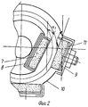
Сущность изобретения поясняется чертежами, где на фиг.1 показан общий вид шелушильной машины, на фиг.2 - вид сверху рабочей камеры машины.The invention is illustrated by drawings, where figure 1 shows a General view of a peeling machine, figure 2 is a top view of the working chamber of the machine.
Шелушильная машина содержит корпус 1, приемный патрубок 2, вертикальный вал 3, охватывающий его неподвижный перфорированный цилиндр 4, выходной патрубок 5 для продуктов шелушения, отводящий патрубок 6 для отсоса воздуха с мелкими продуктами шелушения и привод вала 3. На валу 3 радиально установлены абразивные рабочие органы 1, которые равномерно расположены по валу и жестко закреплены в пазах 8 с возможностью радиального перемещения и регулирования прокладками зазора между абразивной поверхностью и цилиндром 4, собранным из чередующихся фрикционных брусков 9 и перфорированных вставок 10. Фрикционные бруски 9 установлены под тупым α2 углом, образованным касательной линией и рабочей стороной фрикционного бруска с возможностью его радиального перемещения установкой прокладок 11.The desquamation machine contains a housing 1, a
Шелушильная машина работает следующим образом.The peeling machine operates as follows.
Зерно поступает внутрь машины через приемный патрубок 2 и под действием центробежных сил инерции, возникающих при вращении вала 3, поступает на внутреннюю поверхность комбинированного сетчато-фрикционного цилиндра 4, по которой скользит, описывая спиральную траекторию, постепенно приближаясь к выходному патрубку 5 в нижней части машины. При этом зерно, попадая в клиновидные зазоры, испытывает многократные сжимающе-истирающие переменные воздействия, приводящие к надкалыванию оболочки. Далее, за счет трения о поверхности абразивных органов 7, брусков 9, перфорированных вставок 10 цилиндра 4 и между собой в рабочем зазоре происходит интенсивное шелушение зерновок. Мелкие частицы, образующиеся в процессе шелушения зерна, проходят через отверстия перфорированных вставок и вместе с воздухом отсасываются из машины через отводящий патрубок 6. Ошелушенное зерно в смеси с другими продуктами шелушения выходит из машины через выходной патрубок 5. Отбирая пробы продуктов шелушения, определяют эффективность шелушения.The grain enters the machine through the
При снижении качества шелушения корректируют рабочий зазор между абразивными поверхностями рабочих органов и фрикционными брусками цилиндра.With a decrease in the quality of peeling, the working gap between the abrasive surfaces of the working bodies and the friction bars of the cylinder are adjusted.
Регулирование зазора осуществляется при полной остановке машины. Для этого прекращают подачу исходного материала и после его удаления из цилиндра останавливают привод. С помощью прокладок определенной толщины, устанавливаемых между основанием вала или цилиндра и фрикционными элементами, компенсируется износ абразивных элементов или фрикционных брусков.The clearance is adjusted when the machine stops completely. To do this, stop supplying the source material and after removing it from the cylinder, the drive is stopped. By means of gaskets of a certain thickness, installed between the base of the shaft or cylinder and the friction elements, the wear of the abrasive elements or friction bars is compensated.
В отличие от прототипа, разворот абразивных рабочих органов в сочетании с добавленными чередующимися фрикционными брусками обеспечивает формирование клиновидных зазоров, в которых зерно получает дополнительное сжимающе-истирающее воздействие, приводящее к интенсификации процесса шелушения интенсификации процесса шелушения.Unlike the prototype, the spread of the abrasive working bodies in combination with the added alternating friction bars provides the formation of wedge-shaped gaps in which the grain receives an additional compressive-abrasive effect, leading to an intensification of the peeling process, intensification of the peeling process.
Использование предлагаемой шелушильной машины обеспечивает по сравнению с прототипом повышение качества готовой крупы за счет интенсификации процесса шелушения, приводит к снижению затрат на ремонт оборудования.The use of the proposed peeling machine provides, in comparison with the prototype, an increase in the quality of the finished cereal due to the intensification of the peeling process, which reduces the cost of repairing equipment.
Claims (1)
Priority Applications (1)
| Application Number | Priority Date | Filing Date | Title |
|---|---|---|---|
| RU2001112753/12A RU2229338C2 (en) | 2001-05-14 | 2001-05-14 | Scouring machine |
Applications Claiming Priority (1)
| Application Number | Priority Date | Filing Date | Title |
|---|---|---|---|
| RU2001112753/12A RU2229338C2 (en) | 2001-05-14 | 2001-05-14 | Scouring machine |
Publications (2)
| Publication Number | Publication Date |
|---|---|
| RU2001112753A RU2001112753A (en) | 2003-07-20 |
| RU2229338C2 true RU2229338C2 (en) | 2004-05-27 |
Family
ID=32678200
Family Applications (1)
| Application Number | Title | Priority Date | Filing Date |
|---|---|---|---|
| RU2001112753/12A RU2229338C2 (en) | 2001-05-14 | 2001-05-14 | Scouring machine |
Country Status (1)
| Country | Link |
|---|---|
| RU (1) | RU2229338C2 (en) |
Cited By (1)
| Publication number | Priority date | Publication date | Assignee | Title |
|---|---|---|---|---|
| RU2652796C1 (en) * | 2015-04-13 | 2018-05-03 | Федеральное государственное бюджетное образовательное учреждение высшего профессионального образования "Красноярский государственный аграрный университет" | Peeler |
-
2001
- 2001-05-14 RU RU2001112753/12A patent/RU2229338C2/en not_active IP Right Cessation
Cited By (1)
| Publication number | Priority date | Publication date | Assignee | Title |
|---|---|---|---|---|
| RU2652796C1 (en) * | 2015-04-13 | 2018-05-03 | Федеральное государственное бюджетное образовательное учреждение высшего профессионального образования "Красноярский государственный аграрный университет" | Peeler |
Similar Documents
| Publication | Publication Date | Title |
|---|---|---|
| US5048407A (en) | Grain husking and polishing machine | |
| US4292890A (en) | Grain polishing and whitening machine | |
| US4637561A (en) | Beater mill having at least one vertically or obliquely extending cylindrical milling chamber | |
| CN86104448A (en) | Pretreatment of wheat milling plant and wheat Flour milling method and device | |
| JPH0775741A (en) | Perforated cylindrical body for bran removal of grinding type vertical grain milling machine | |
| EP0131728B2 (en) | Rice polishing machine | |
| NO820197L (en) | PROCEDURE AND APPARATUS FOR TREATMENT OF CEREALS FROM CEREAL GROWTH | |
| JPH11138024A (en) | Grain polisher | |
| RU2229338C2 (en) | Scouring machine | |
| WO2005046871A1 (en) | Grain-cleaning apparatus | |
| US4017034A (en) | Art of dry milling sorghum and other cereal grains | |
| JPS6164348A (en) | Milling method and device thereof | |
| US5667150A (en) | Pulverizing, filtering, and transporting apparatus | |
| RU2063807C1 (en) | Centrifugal multistage crusher | |
| US5830042A (en) | Surface abrasive treatment of small objects | |
| RU2396122C1 (en) | Device for grinding and separation of feed grains | |
| RU2414303C1 (en) | Apparatus for grinding of loose materials | |
| US2499590A (en) | Grain hulling machine | |
| RU2447942C2 (en) | Centrifugal multistage grain crusher | |
| JP3790864B2 (en) | Grinding / friction type rice milling machine | |
| US10625267B2 (en) | Device and grinding tool for comminuting feed material | |
| JP4572855B2 (en) | Vertical rice milling equipment | |
| KR100501712B1 (en) | Method and device for crushing of bulk materials | |
| RU2077384C1 (en) | Device for individual scouring of grains | |
| RU2138330C1 (en) | Hulling and milling machine |
Legal Events
| Date | Code | Title | Description |
|---|---|---|---|
| MM4A | The patent is invalid due to non-payment of fees |
Effective date: 20040515 |