RU2224924C2 - Device for control of tension of band-and-shoe brake - Google Patents
Device for control of tension of band-and-shoe brake Download PDFInfo
- Publication number
- RU2224924C2 RU2224924C2 RU2002106491/11A RU2002106491A RU2224924C2 RU 2224924 C2 RU2224924 C2 RU 2224924C2 RU 2002106491/11 A RU2002106491/11 A RU 2002106491/11A RU 2002106491 A RU2002106491 A RU 2002106491A RU 2224924 C2 RU2224924 C2 RU 2224924C2
- Authority
- RU
- Russia
- Prior art keywords
- brake
- gear
- band
- tension
- tape
- Prior art date
Links
- 230000007246 mechanism Effects 0.000 claims abstract description 8
- 230000005540 biological transmission Effects 0.000 claims description 4
- 230000003071 parasitic effect Effects 0.000 claims 1
- 238000011089 mechanical engineering Methods 0.000 abstract description 2
- 239000000126 substance Substances 0.000 abstract 1
- 239000010754 BS 2869 Class F Substances 0.000 description 2
- 230000008719 thickening Effects 0.000 description 2
- 241000282320 Panthera leo Species 0.000 description 1
- 230000000712 assembly Effects 0.000 description 1
- 238000000429 assembly Methods 0.000 description 1
- 230000003111 delayed effect Effects 0.000 description 1
Images
Landscapes
- Braking Arrangements (AREA)
Abstract
Description
Изобретение относится к устройствам для затяжки ленточно-колодочного тормоза и может быть использовано в тормозных устройствах, применяемых в машиностроении. The invention relates to devices for tightening the tape-shoe brake and can be used in braking devices used in mechanical engineering.
Известно устройство затяжки ленточного тормоза, содержащее раму, представляющую собой неподвижный корпус тормоза, тормозной цилиндр с толкателями, установленный на раме, тормозную ленту, ползунный механизм, образованный за счет соединения ленты с толкателем с помощью оси, расположенной с возможностью осевого перемещения в пазу, выполняющем роль направляющей, и соединенного с обеих сторон с концами ленты [аналог, а.с. СССР 1030597, кл. F 16 D 65/52 за 1981 г.]. A device for tightening a belt brake comprising a frame, which is a stationary brake housing, a brake cylinder with pushers mounted on a frame, a brake band, a slider mechanism formed by connecting the belt to the pusher using an axis located with the possibility of axial movement in the groove, performing the role of the guide, and connected on both sides with the ends of the tape [analogue, a.s. USSR 1030597, class F 16 D 65/52 for 1981].
Данное устройство имеет тот недостаток, что не осуществляется перераспределение усилий натяжений ветвей тормозной ленты в зависимости от изменения направления вращения шкива. This device has the disadvantage that the redistribution of the efforts of the tension of the branches of the brake tape is not carried out depending on the change in the direction of rotation of the pulley.
Известно применение в приводе ленточно-колодочного тормоза зубчатой передачи типа "зубчатое колесо - рейка", являющейся частным случаем передачи "зубчатое колесо - сектор", когда радиус сектора равен бесконечности (прототип, а.с. СССР 496399, кл. F 16 D 49/08 за 1974 г.). It is known to use a gear-type gear-rack gear in a tape-shoe brake drive, which is a special case of a gear-sector gear when the radius of the sector is infinity (prototype, AS USSR 496399, class F 16 D 49 / 08 for 1974).
Применение в приводе только передачи типа "зубчатое колесо - рейка" не позволяет эффективно управлять затяжкой лентой тормоза. The use in the drive of only gears of the type "gear wheel - rack" does not allow you to effectively control the tightening of the brake band.
Предложенное техническое решение по сравнению с аналогом и прототипом имеет следующие отличительные признаки:
- реализуется управление затяжкой ветвей тормозной ленты;
- обеспечивается перераспределение усилий натяжений ветвей тормозной лентой в зависимости от изменения направления вращения шкива;
- сокращается время на замену изношенных фрикционных накладок на новые;
- наличие на наружной поверхности тормозной ленты фрикционных накладок позволяет использовать данный тормоз как двухступенчатый, обхватив дополнительной тормозной лентой накладки основной ленты.The proposed technical solution in comparison with the analogue and prototype has the following distinctive features:
- the tightening of the brake tape branches is implemented;
- provides redistribution of the efforts of the tension of the branches of the brake tape, depending on the change in the direction of rotation of the pulley;
- reduced time to replace worn friction linings with new ones;
- the presence on the outer surface of the brake band of friction linings allows you to use this brake as a two-stage, wrapping an additional brake band around the lining of the main belt.
Целью настоящего изобретения является повышение эксплуатационных параметров ленточно-колодочного тормоза путем управления затяжкой его тормозной лентой. The aim of the present invention is to increase the operational parameters of the tape brake shoe by controlling the tightening of its brake band.
Поставленная цель достигается тем, что устройство натяжения тормозной лентой содержит перекрещивающиеся тяги, находящиеся в одной плоскости и присоединенные с одной стороны к обоим концам ветвей нерегулируемыми вилками, а с другой они соединены шарнирно с регулируемыми вилками с ползунами кривошипно-ползунного механизма, взаимодействующего с одной стороны через передачу "сектор - зубчатое колесо", а с другой - через передачу "паразитное зубчатое колесо - сектор", т.е. с двух сторон с зубчатым колесом рычага управления, обеспечивающим перераспределение натяжения ветвей с фрикционными накладками вне зависимости от направления вращения тормозного шкива. This goal is achieved by the fact that the brake belt tension device contains crossing rods located in the same plane and connected on one side to both ends of the branches by unregulated forks, and on the other they are pivotally connected to adjustable forks with sliders of a crank-slide mechanism interacting on one side through the transmission "sector - gear", and on the other - through the transmission "spurious gear - sector", i.e. on both sides with a gear wheel of the control lever, providing redistribution of the tension of the branches with friction linings, regardless of the direction of rotation of the brake pulley.
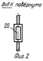
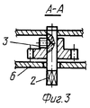
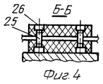
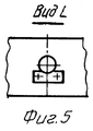
Устройство для управления затяжкой ленточно-колодочного тормоза показано на фиг. 1, общий вид; на фиг.2 - вид по стрелке К фиг. 1 (утолщение с прямоугольным вырезом; на фиг. 3 - разрез А - А на фиг.1; на фиг.4 - разрез Б-Б на фиг1; на фиг. 5 - вид по стрелке L фиг.1 (стопорение оси планкой). A device for controlling the tightening of the band brake is shown in FIG. 1, general view; FIG. 2 is a view along arrow K of FIG. 1 (a thickening with a rectangular cut; in Fig. 3, a section A - A in Fig. 1; in Fig. 4, a section B-B in Fig. 1; in Fig. 5, a view along arrow L of Fig. 1 (locking the axis with a bar) .
Устройство для управления затяжкой ленточно-колодочного тормоза состоит из зубчатой передачи, содержащей шестерню 1, закрепленную на валу 2 винтом 3, и зубчатый сектор 4, который свободно сидит на поперечной оси 5. Вал 2 и ось 5 установлены в ребордах 6 продольной оси 7, стопорящейся в раме 16 планками 17, которые крепятся к ней с помощью винтов 18. The device for controlling the tightening of the tape-shoe brake consists of a gear train comprising a gear 1 fixed to the shaft 2 by a screw 3, and a gear sector 4, which sits freely on the transverse axis 5. The shaft 2 and the axis 5 are mounted in
Зубчатый сектор 4 имеет кривошип 8, шарнирно соединенный с шатуном 9. Последний шарнирно связан с правым ползуном 10, который может перемещаться по цилиндрической направляющей оси 7. Тяга 11 одним концом соединена шарнирно с ползуном 10, а другим - с нерегулируемой вилкой 12, прикрепленной к тормозной ленте 13, с двух сторон которой установлены податливые фрикционные накладки 24, крепящиеся к ней с помощью шпилек 25 и специальных вставок 26. The gear sector 4 has a crank 8 pivotally connected to the connecting rod 9. The latter is pivotally connected to the right slider 10, which can move along the cylindrical guide axis 7. The rod 11 is pivotally connected to the slider 10 at one end and the unregulated fork 12 attached to the other a brake tape 13, on both sides of which compliant friction linings 24 are mounted, fastened to it by means of
Такая конструкция крепления податливых фрикционных накладок 24 на тормозной ленте 13 с помощью шпилек 25 и специальных вставок 26 позволяет существенно уменьшить время на замену сношенных на новые накладки. Это достигается путем отсоединения нерегулируемых вилок 12 от концов ветвей (а, б) тормозной ленты 13 ее переворотом, т.е. противоположного подсоединения. Таким образом, изношенные фрикционные накладки 24 окажутся сверху на тормозной ленте 13, что и даст возможность произвести их замену. This design of mounting compliant friction linings 24 on the brake belt 13 using the
Наличие на наружной поверхности тормозной ленты 13 фрикционных накладок 24 позволяет использовать данный ленточно-колодочный тормоз как двухступенчатый, обхватив второй тормозной лентой накладки 24 первой лентой 13. The presence on the outer surface of the brake tape 13 of the friction linings 24 allows you to use this tape-shoe brake as a two-stage, grasping the second brake tape of the lining 24 with the first tape 13.
Для регулирования зазора между тормозной лентой 13 и шкивом 22 по мере износа слабого элемента фрикционных узлов, т.е. фрикционных накладок 24, тяги 11 и 23 имеют регулируемые вилки 14, которые навинчиваются на них и стопорятся гайками 15. To regulate the gap between the brake band 13 and the pulley 22 as the weak element of the friction assemblies wear out, i.e. friction linings 24, rods 11 and 23 have adjustable forks 14, which are screwed onto them and locked with nuts 15.
Управление затяжкой тормозной лентой 13 достигается рычагом 19, который устанавливается на квадратный конец вала 2. В нижней части правая тяга 11 имеет утолщения с прямоугольным вырезом 20, через который проходит левая тяга 23, что позволяет им находиться в одной плоскости. Паразитная шестерня 21 обеспечивает движение ползуна 10 влево. The control of the tightening of the brake tape 13 is achieved by a lever 19, which is mounted on the square end of the shaft 2. In the lower part, the right link 11 has thickenings with a
Устройство для управления затяжкой ленточно-колодочного тормоза работает следующим образом. A device for controlling the tightening of the tape-shoe brake operates as follows.
При повороте рычага управления 19 против часовой стрелки поварачивается в этом же направлении шестерня 1, приводя при этом во вращение зубчатый сектор 4. В то же время кривошип 8 движется по часовой стрелке и через шатун 9 передает движение ползуну 10, который смещается по продольной оси 7 вправо, способствуя при этом через правую тягу 11 затягиванию набегающей ветви (а) тормозной ленты 13 с фрикционными накладками 24 на тормозном шкиве 22. Одновременно от шестерни 1 через паразитное зубчатое колесо 21, через левый кривошипно-ползунный механизм и левую тягу 23 затягивается сбегающая ветвь (б) тормозной ленты 13. При повороте рычага управления 19 по часовой стрелке затягивание ветвей (а, б) тормозной ленты 13 с фрикционными накладками 24 на тормозном шкиве 22 производится в противоположном порядке. Кроме того, усилие затяжки на рычаге управления можно существенно уменьшить, исходя из условия, что Fп = S/u•η, где S - усилие натяжения одной из ветвей тормозной ленты, u - передаточное отношение механизма между концами ветвей тормозной ленты и рычагом управления; η - общий коэффициент полезного действия механизма. При этом невилируется понятие набегающая (а) и сбегающая (б) ветвь тормозной ленты при любом направлении вращения тормозного шкива 22, что ведет к выравниванию удельных нагрузок на поверхностях фрикционных узлов ленточно-колодочного тормоза, и, как следствие, к их почти равномерному износу.When the control lever 19 is rotated counterclockwise, gear 1 rotates in the same direction, causing the gear sector 4 to rotate. At the same time, the crank 8 moves clockwise and transmits the movement to the slider 10 through the connecting rod 9, which moves along the longitudinal axis 7 to the right, while facilitating through the right link 11 to tighten the oncoming branch (a) of the brake band 13 with friction linings 24 on the brake pulley 22. Simultaneously from gear 1 through the spurious gear wheel 21, through the left crank-slide mechanism and the lion w rod 23 escapes delayed branch (b) of the brake band 13. When the control lever 19 is rotated clockwise tightening the branches (a, b) of the brake band 13 with friction linings 24 on the brake pulley 22 is made in the opposite order. In addition, the tightening force on the control lever can be significantly reduced, based on the condition that F p = S / u • η, where S is the tension force of one of the branches of the brake belt, u is the gear ratio between the ends of the branches of the brake belt and the control lever ; η is the overall efficiency of the mechanism. At the same time, the concept of running (a) and running (b) branch of the brake belt for any direction of rotation of the brake pulley 22 is not ignored, which leads to the equalization of specific loads on the surfaces of the friction units of the tape-shoe brake, and, as a result, to their almost uniform wear.
Claims (1)
Priority Applications (1)
| Application Number | Priority Date | Filing Date | Title |
|---|---|---|---|
| RU2002106491/11A RU2224924C2 (en) | 2002-03-13 | 2002-03-13 | Device for control of tension of band-and-shoe brake |
Applications Claiming Priority (1)
| Application Number | Priority Date | Filing Date | Title |
|---|---|---|---|
| RU2002106491/11A RU2224924C2 (en) | 2002-03-13 | 2002-03-13 | Device for control of tension of band-and-shoe brake |
Publications (2)
| Publication Number | Publication Date |
|---|---|
| RU2224924C2 true RU2224924C2 (en) | 2004-02-27 |
| RU2002106491A RU2002106491A (en) | 2004-03-27 |
Family
ID=32172427
Family Applications (1)
| Application Number | Title | Priority Date | Filing Date |
|---|---|---|---|
| RU2002106491/11A RU2224924C2 (en) | 2002-03-13 | 2002-03-13 | Device for control of tension of band-and-shoe brake |
Country Status (1)
| Country | Link |
|---|---|
| RU (1) | RU2224924C2 (en) |
Cited By (3)
| Publication number | Priority date | Publication date | Assignee | Title |
|---|---|---|---|---|
| RU2382252C1 (en) * | 2008-12-03 | 2010-02-20 | Государственное образовательное учреждение высшего профессионального образования "Санкт-Петербургский государственный горный институт имени Г.В. Плеханова (технический университет)" | Differential band brake |
| RU2382251C1 (en) * | 2008-12-03 | 2010-02-20 | Государственное образовательное учреждение высшего профессионального образования "Санкт-Петербургский государственный горный институт имени Г.В. Плеханова (технический университет)" | Differential band brake for irreversible mechanisms |
| RU2383794C1 (en) * | 2008-12-03 | 2010-03-10 | Государственное образовательное учреждение высшего профессионального образования "Санкт-Петербургский государственный горный институт имени Г.В. Плеханова (технический университет)" | Band brake |
Citations (5)
| Publication number | Priority date | Publication date | Assignee | Title |
|---|---|---|---|---|
| SU496399A1 (en) * | 1974-06-10 | 1975-12-25 | Челябинский Политехнический Институт | Band brake tightening device |
| SU765554A1 (en) * | 1975-03-07 | 1980-09-23 | Предприятие П/Я В-2302 | Belt brake |
| US4241813A (en) * | 1979-06-29 | 1980-12-30 | The Bendix Corporation | Band brake parking lever |
| SU1030597A1 (en) * | 1981-06-17 | 1983-07-23 | Предприятие П/Я А-3681 | Device for automatic control of clearance in slider-type brake |
| US6068092A (en) * | 1995-02-21 | 2000-05-30 | Nsk-Warner K.K. | Brake band |
-
2002
- 2002-03-13 RU RU2002106491/11A patent/RU2224924C2/en not_active IP Right Cessation
Patent Citations (5)
| Publication number | Priority date | Publication date | Assignee | Title |
|---|---|---|---|---|
| SU496399A1 (en) * | 1974-06-10 | 1975-12-25 | Челябинский Политехнический Институт | Band brake tightening device |
| SU765554A1 (en) * | 1975-03-07 | 1980-09-23 | Предприятие П/Я В-2302 | Belt brake |
| US4241813A (en) * | 1979-06-29 | 1980-12-30 | The Bendix Corporation | Band brake parking lever |
| SU1030597A1 (en) * | 1981-06-17 | 1983-07-23 | Предприятие П/Я А-3681 | Device for automatic control of clearance in slider-type brake |
| US6068092A (en) * | 1995-02-21 | 2000-05-30 | Nsk-Warner K.K. | Brake band |
Non-Patent Citations (1)
| Title |
|---|
| Александров М.П., Лысяков А.Г. и др. Тормозные устройства (справочник). - М.: Машиностроение, 1985. Алексеевский Г.В. Буровые установки Уралмашзавода. - М.: Недра, 1981. * |
Cited By (3)
| Publication number | Priority date | Publication date | Assignee | Title |
|---|---|---|---|---|
| RU2382252C1 (en) * | 2008-12-03 | 2010-02-20 | Государственное образовательное учреждение высшего профессионального образования "Санкт-Петербургский государственный горный институт имени Г.В. Плеханова (технический университет)" | Differential band brake |
| RU2382251C1 (en) * | 2008-12-03 | 2010-02-20 | Государственное образовательное учреждение высшего профессионального образования "Санкт-Петербургский государственный горный институт имени Г.В. Плеханова (технический университет)" | Differential band brake for irreversible mechanisms |
| RU2383794C1 (en) * | 2008-12-03 | 2010-03-10 | Государственное образовательное учреждение высшего профессионального образования "Санкт-Петербургский государственный горный институт имени Г.В. Плеханова (технический университет)" | Band brake |
Also Published As
| Publication number | Publication date |
|---|---|
| RU2002106491A (en) | 2004-03-27 |
Similar Documents
| Publication | Publication Date | Title |
|---|---|---|
| US4030373A (en) | Variable speed drive for a bicycle | |
| JP4741047B2 (en) | Drive device for advancing elongate elements | |
| RU2224924C2 (en) | Device for control of tension of band-and-shoe brake | |
| RU2005123384A (en) | BRAKING MECHANISM FOR DISK BRAKE | |
| CA2101393A1 (en) | Braking system for in-line roller skates | |
| US4800768A (en) | Power transmission apparatus | |
| US6129646A (en) | Apparatus for propelling a cycle | |
| FR2367946A1 (en) | SELF-LOADING BRAKE LINKAGE | |
| US7632200B2 (en) | Common link dual arm tensioning device | |
| US6123635A (en) | Propulsion apparatus for a cycle | |
| FI79937C (en) | DRAGANORDNING FOER GARDIN. | |
| RU2263832C2 (en) | Belt-block brake | |
| CA2633831A1 (en) | Motor brake | |
| RU2382251C1 (en) | Differential band brake for irreversible mechanisms | |
| CA1148879A (en) | Braking device for rail vehicles | |
| CN110883765A (en) | A dexterous hand tensioner for wire drives that can automatically adjust the tightness | |
| SU879105A1 (en) | Tensioning apparatus for flexible-link transmissions | |
| CN206246621U (en) | Stretcher | |
| RU2383794C1 (en) | Band brake | |
| RU2432509C2 (en) | Belt-shoe brake with fixed and moving friction linings on brake belt | |
| RU2382252C1 (en) | Differential band brake | |
| RU2159205C1 (en) | Inclined belt conveyor | |
| RU2002106490A (en) | Tape-brake brake with controlled mechanical drive | |
| RU2224925C2 (en) | Device for tightening brake band on pulley | |
| RU2780637C2 (en) | Brake unit of disc brake of railway vehicle |
Legal Events
| Date | Code | Title | Description |
|---|---|---|---|
| MM4A | The patent is invalid due to non-payment of fees |
Effective date: 20070314 |