RU2222862C2 - Method for electric power supply under starting and steady state conditions to permanent-magnet synchronous motor including that designed to set in motion hydraulic pump - Google Patents
Method for electric power supply under starting and steady state conditions to permanent-magnet synchronous motor including that designed to set in motion hydraulic pump Download PDFInfo
- Publication number
- RU2222862C2 RU2222862C2 RU2000111468/09A RU2000111468A RU2222862C2 RU 2222862 C2 RU2222862 C2 RU 2222862C2 RU 2000111468/09 A RU2000111468/09 A RU 2000111468/09A RU 2000111468 A RU2000111468 A RU 2000111468A RU 2222862 C2 RU2222862 C2 RU 2222862C2
- Authority
- RU
- Russia
- Prior art keywords
- rotor
- current
- stage
- starting
- steady state
- Prior art date
Links
Images


Classifications
-
- H—ELECTRICITY
- H02—GENERATION; CONVERSION OR DISTRIBUTION OF ELECTRIC POWER
- H02P—CONTROL OR REGULATION OF ELECTRIC MOTORS, ELECTRIC GENERATORS OR DYNAMO-ELECTRIC CONVERTERS; CONTROLLING TRANSFORMERS, REACTORS OR CHOKE COILS
- H02P6/00—Arrangements for controlling synchronous motors or other dynamo-electric motors using electronic commutation dependent on the rotor position; Electronic commutators therefor
- H02P6/20—Arrangements for starting
- H02P6/22—Arrangements for starting in a selected direction of rotation
Abstract
Description
Область технического применения
Изобретение относится к способу электропитания в пусковом и установившемся режимах синхронного двигателя с постоянными магнитами, в частности, предназначенного для приведения в движение гидравлического насоса центробежного типа.Scope of technical application
The invention relates to a method of power supply in the starting and steady-state modes of a permanent magnet synchronous motor, in particular, intended for driving a centrifugal type hydraulic pump.
Предпосылки для создания изобретения
Синхронные двигатели с постоянными магнитами весьма предпочтительны, поскольку они высокоэффективны в работе.Background to the invention
Permanent magnet synchronous motors are highly preferred as they are highly efficient in operation.
Однако проблемой, которая, в частности, возникает в отношении двигателей высокой мощности, приводящих в движение нагрузки, имеющие значительную инерцию, является пусковая стадия. However, the problem, which, in particular, arises in relation to high-power engines driving loads with significant inertia, is the starting stage.
Согласно известному уровню техники для решения этой проблемы используют механические средства или процессы электронного управления. According to the prior art, mechanical means or electronic control processes are used to solve this problem.
Механические средства, в частности, предполагают отсоединение рабочих колес насосов, приводимых в движение, так что ротор может свободно начать движение на протяжении угла, составляющего менее 360o, а затем войти в зацепление с рабочим колесом и продолжить свое движение.Mechanical means, in particular, involve disconnecting the impellers of the pumps driven, so that the rotor can freely begin to move over an angle of less than 360 o , and then engage with the impeller and continue its movement.
Очевидно, что это решение может быть использовано, когда ротор обладает невысокой механической инерцией, которая в любом случае позволяет ему достичь установившегося режима за полупериод, если, что обычно имеет место, ротор имеет два полюса. Obviously, this solution can be used when the rotor has a low mechanical inertia, which in any case allows it to reach the steady state in a half period, if, as is usually the case, the rotor has two poles.
На практике это означает, что невозможно использовать эти механические устройства, чтобы иметь насос средней и высокой мощности, включающий в себя ротор, размеры, а следовательно и инерция которого, являются функцией упомянутой мощности. In practice, this means that it is impossible to use these mechanical devices to have a medium and high power pump, which includes a rotor, the dimensions, and therefore the inertia of which, are a function of the mentioned power.
Также известны процессы электронного пуска, при которых управление ротором осуществляют по его положению и синусоидальный ток сети "усекают" статическими переключателями, так что он находится в фазе, которая не противоположна перемещению ротора. Electronic start-up processes are also known in which the rotor is controlled by its position and the sinusoidal current of the network is "truncated" by static switches, so that it is in a phase that is not opposite to the movement of the rotor.
Такое решение, при котором используют ток без модификации частоты сети, не позволяет достичь высоких статических крутящих моментов, а следовательно не позволяет обеспечить электропитание двигателей средней и высокой мощности. Such a solution, in which current is used without modifying the network frequency, does not allow to achieve high static torques, and therefore does not allow to provide power to medium and high power motors.
При других способах используют инвертор, генерирующий форму волны, частота которой постепенно повышается, причем режим этой частоты заблаговременно запоминается в цепи электропитания. Other methods use an inverter that generates a waveform whose frequency is gradually increasing, and the mode of this frequency is stored in advance in the power circuit.
Это решение также приводит к значительным проблемам, поскольку все электромоторы с постоянными магнитами отличаются друг от друга, в частности, в отношении магнитных характеристик ротора, несмотря на изготовление с идентичными размерами. This solution also leads to significant problems, since all permanent magnet electric motors differ from each other, in particular with respect to the magnetic characteristics of the rotor, despite the manufacture with identical dimensions.
Двигатели этого типа также отличаются в отношении пакета статора. Motors of this type also differ with respect to the stator package.
В отношении статора проблему можно считать умеренной, поскольку различия могут иметь место только из-за пластинчатого пакета и обмоток катушки. With respect to the stator, the problem can be considered moderate, since differences can only occur due to the plate package and the coil windings.
Однако эти различия не имеют особого значения и не важны в смысле влияния на магнитную цепь. However, these differences are not of particular importance and are not important in the sense of influencing the magnetic circuit.
Наибольшие различия встречаются в роторах, поскольку они не идентичны и, в частности, никогда не имеют одинаковое и постоянное направление северного и южного полей. The greatest differences are found in rotors, since they are not identical and, in particular, never have the same and constant direction of the northern and southern fields.
Всегда имеется север и юг, но в отношении геометрии ротора, формы полей обычно представляют собой формы, обозначенные на фиг.2 позициями 10 и 11 применительно к цилиндрическому ротору с постоянными магнитами, обозначенному позицией 12. There is always north and south, but with respect to rotor geometry, field shapes are usually the shapes indicated in FIG. 2 by 10 and 11 with respect to a cylindrical permanent magnet rotor indicated by 12.
Это прежде всего влечет за собой асимметрию движения ротора, так что двигатель работает неравномерно. This primarily entails the asymmetry of the rotor, so that the engine runs unevenly.
Типичный двигатель, имеющий ротор с постоянными магнитами, на фиг.1 в общем обозначен позицией 13, при этом ротор обозначен позицией 14 и наводится между двумя полюсами, изготовленными из пластин 15 и 16, представляющими собой концы статорного пакета 17, на которых установлены две катушки 18 и 19, возбуждающие поле статора. A typical motor having a rotor with permanent magnets, in figure 1 is generally indicated by 13, while the rotor is indicated by 14 and is induced between two poles made of plates 15 and 16, representing the ends of the stator pack 17 on which two coils are mounted 18 and 19, exciting the stator field.
Чтобы обеспечить преимущество для одного направления вращения ротора, полюсы имеют углубления 20 и 21, которые определяют ось симметрии 22 ротора 14 под углом по отношению к срединной оси полюсов 15 и 16. To provide an advantage for one direction of rotation of the rotor, the poles have recesses 20 and 21, which define the axis of symmetry 22 of the rotor 14 at an angle with respect to the median axis of the poles 15 and 16.
Также имеется датчик 23 положения, который установлен в промежуточной зоне между полюсами 15 и 16. There is also a position sensor 23, which is installed in the intermediate zone between the poles 15 and 16.
Эта обычная конструкция создает дополнительную проблему вследствие смещения нейтральной оси ротора по отношению к положению датчика 23. This conventional design creates an additional problem due to the displacement of the neutral axis of the rotor relative to the position of the sensor 23.
Все эти проблемы препятствуют получению точных сведений о магнитной структуре двигателя и о его действительных характеристиках. All these problems impede obtaining accurate information about the magnetic structure of the engine and its actual characteristics.
Другая проблема возникает вследствие того, что предлагаемый способ пуска связан с сочетанием синхронного двигателя с постоянными магнитами и центробежного гидравлического насоса. Another problem arises because the proposed starting method is associated with a combination of a permanent magnet synchronous motor and a centrifugal hydraulic pump.
Механические-гидравлические характеристики насоса также составляют проблему пуска, поскольку они тоже неизвестны и не могут быть точно предсказаны. The mechanical-hydraulic characteristics of the pump also constitute a start-up problem, since they are also unknown and cannot be accurately predicted.
В пуск гидравлического насоса по существу вовлечены многие факторы. Many factors are involved in starting up a hydraulic pump.
Например, если насос длительное время находится в неподвижном состоянии, могут возникнуть проблемы в отношении осаждения продуктов, транспортируемых водой, которые создают неизвестные начальные нагрузки. For example, if the pump is stationary for a long time, problems may arise regarding the deposition of products transported by water, which create unknown initial loads.
Эта проблема также может иметь место в течение вращения, когда транспортируемые объекты располагаются в камере рабочего колеса, а иногда в месте заклинивания и стопорения вращения насоса. This problem can also occur during rotation, when the transported objects are located in the chamber of the impeller, and sometimes in the place of jamming and stopping the rotation of the pump.
Сущность изобретения
Цель настоящего изобретения заключается в создании способа электропитания при пусковом и установившемся режимах синхронного двигателя с постоянными магнитами, в частности предназначенного для приведения в движение центробежного гидравлического насоса, который позволяет устранить все упомянутые проблемы и, в частности, пригоден для решения проблем каждого отдельного двигателя.SUMMARY OF THE INVENTION
The purpose of the present invention is to provide a method of power supply during starting and steady state conditions of a permanent magnet synchronous motor, in particular intended for driving a centrifugal hydraulic pump, which eliminates all of the above problems and, in particular, is suitable for solving the problems of each individual motor.
Следующая основная цель заключается в создании способа, который обеспечивает пуск синхронных электродвигателей с постоянными магнитами даже средней мощности и от средней до высокой мощности и в заданном направлении. The next main goal is to create a method that enables the launch of synchronous permanent magnet motors even of medium power and medium to high power in a given direction.
Следующая основная цель заключается в создании способа пускового и последующего электропитания синхронных двигателей с постоянными магнитами, который сводит к минимуму поглощение энергии в течение пуска и в установившемся режиме. The next main goal is to create a method of starting and subsequent power supply of permanent magnet synchronous motors, which minimizes energy absorption during start-up and in steady state.
Другая важная цель заключается в создании способа электропитания в установившемся режиме синхронного двигателя с постоянными магнитами, при котором соsФ практически равен 1. Another important goal is to create a method of power supply in the steady state of a permanent magnet synchronous motor, at which the cosf is practically equal to 1.
Эти и другие цели, которые будут очевидны из нижеуказанного, достигаются способом электропитания в пусковом и установившемся режимах синхронного двигателя с постоянными магнитами, в частности предназначенного для приведения в движение центробежного гидравлического насоса, отличающимся тем, что он содержит следующие стадии:
1) стадию изучения, в течение которой ротор совершает два последовательных оборота, охватывающих 180o, с подачей к статору постоянного пускового тока для первых 180o, его преобразованием для вторых 180o после того, как ротор достиг первые 180o, и запоминанием посредством памяти, которая находится в цепи электропитания, в сочетании с линейным магнитным датчиком положения рабочих характеристик в определенном количестве отдельных точек, которые соответствуют заданным угловым положениям ротора, и определением в течение этой стадии пускового тока и реального нулевого положения ротора;
2) пусковую стадию, в течение которой более сильный ток, чем пусковой ток, определенный в течение первой стадии, подают с первоначально низкой частотой, которая затем постепенно увеличивается, при этом обеспечиваются ожидание и проверка посредством линейного датчика прохождения ротора 80 и 100o и далее 260 и 280o;
3) стадию установившегося режима, в течение которой как только достигается частота установившегося режима, а следовательно и скорость установившегося режима, подаваемый ток практически представляет собой синусоидальный ток и ротор ожидается у перехода через нулевые точки перед инвертированием направления тока;
обеспечиваются функции управления, которые, если ротор замедляется в течение стадии установившегося режима, возвращают процесс к пусковой стадии, и которые в случае стопорения ротора, изменения направления вращения на обратное, отказа линейного датчика или непоследовательностей, возвращают процесс к стадии изучения.These and other goals, which will be obvious from the following, are achieved by the method of power supply in the starting and steady state modes of a permanent magnet synchronous motor, in particular intended for driving a centrifugal hydraulic pump, characterized in that it comprises the following stages:
1) the study stage, during which the rotor makes two consecutive turns, covering 180 o , applying a constant inrush current to the stator for the first 180 o , converting it to the second 180 o after the rotor reaches the first 180 o , and memorizing through memory , which is located in the power supply circuit, in combination with a linear magnetic sensor of the position of the operating characteristics in a certain number of individual points that correspond to the given angular positions of the rotor, and the determination of the starting current during this stage and the real zero position of the rotor;
2) the starting stage, during which a stronger current than the starting current determined during the first stage is supplied with an initially low frequency, which then gradually increases, while waiting and checking by means of a linear rotor passage sensor of 80 and 100 o and further 260 and 280 o ;
3) the stage of the steady state, during which as soon as the frequency of the steady state, and therefore the speed of the steady state, is reached, the supplied current is practically a sinusoidal current and the rotor is expected at the transition through zero points before inverting the current direction;
control functions are provided that, if the rotor slows down during the steady state stage, returns the process to the starting stage, and which, if the rotor stops, reverses the rotation direction, the linear sensor fails or inconsistencies, returns the process to the study stage.
Краткое описание фигур
Другие характеристики и преимущества настоящего изобретения будут более очевидны из приведенного ниже подробного описания предпочтительного варианта осуществления способа, представленного на прилагаемых фигурах, на которых:
на фиг. 1, которая уже описана, представлено примерное схематическое изображение конструкции синхронного двигателя с постоянными магнитами, к которому применен способ;
на фиг. 2, которая уже описана, представлено неправильное расположение магнитного поля ротора с постоянными магнитами;
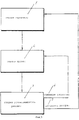
на фиг. 3 представлена схема прохождения трех стадий способа и их взаимосвязь;
на фиг.4 представлена схема прохождения стадии изучения;
на фиг.5 представлена схема прохождения пусковой стадии;
на фиг.6 представлена схема прохождения стадии установившегося режима;
на фиг. 7 представлена кривая тока в течение стадии изучения, пока не произойдет первое перемещение ротора;
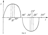
на фиг.8 представлена кривая тока при первых двух поворотах на 180o;
на фиг.9 представлена кривая тока от стадии изучения до пусковой стадии и далее до стадии установившегося режима.Brief Description of the Figures
Other characteristics and advantages of the present invention will be more apparent from the following detailed description of a preferred embodiment of the method presented in the accompanying figures, in which:
in FIG. 1, which has already been described, an exemplary schematic illustration of the construction of a permanent magnet synchronous motor to which the method is applied;
in FIG. 2, which has already been described, presents the incorrect location of the magnetic field of the rotor with permanent magnets;
in FIG. 3 shows a diagram of the passage of the three stages of the method and their relationship;
figure 4 presents a diagram of the passage of the study stage;
figure 5 presents a diagram of the passage of the launch stage;
figure 6 presents a diagram of the passage of the stage of steady state;
in FIG. 7 shows a current curve during the study phase until the first rotor movement occurs;
on Fig presents a current curve during the first two turns of 180 o ;
figure 9 presents the current curve from the study stage to the start-up stage and then to the stage of steady state.
Варианты осуществления изобретения
Способ согласно изобретению состоит из трех стадий, что схематически представлено на фиг.3:
1) стадии изучения;
2) пусковой стадии;
3) стадии установившегося режима.Embodiments of the invention
The method according to the invention consists of three stages, which is schematically represented in figure 3:
1) stages of study;
2) starting stage;
3) stages of the steady state.
Схема согласно фиг.3 иллюстрирует прохождение обратной связи, более подробно описанной ниже, при этом на ней показано, что если ротор замедляется в течение стадии установившегося режима, процесс возвращается к пусковой стадии, при этом, если ротор останавливается или в течение стадии установившегося режима происходят другие аномалии, процесс возвращается к стадии изучения. The diagram according to Fig. 3 illustrates the passage of feedback, described in more detail below, while it shows that if the rotor slows down during the steady state stage, the process returns to the starting stage, while if the rotor stops or during the steady state stage other anomalies, the process returns to the study stage.
В течение стадии изучения (фиг. 4) ротор поворачивается на 180o посредством подачи к полю статора постоянного тока малой величины.During the study stage (Fig. 4), the rotor rotates 180 ° by supplying a small amount of direct current to the stator field.
Эта стадия более четко представлена на фиг.1, где показано, что производится подача постоянного тока, при этом он изменяется с постепенным повышением сил, которые в интервалах 24 и 25 не обеспечивают движение ротора, в то время как интервал 26 характеризует ток, при котором ротор поворачивается так, чтобы после вращения на 180o достичь положения, которое соответствует положению, определяемому магнитным полем полюсов 15 и 16, при этом дальнейшее вращение на 180o происходит в последующем интервале, поскольку поле меняется на обратное.This stage is more clearly presented in Fig. 1, where it is shown that direct current is supplied, while it changes with a gradual increase in forces that in the
Причина изменения тока за периоды, которые могут составлять порядка 200 мс, состоит в том, что даже если ротор находился в положении согласования с магнитным полем, в последующем интервале он подвергается вращению на 180o.The reason for the change in current over periods that can be of the order of 200 ms is that even if the rotor was in alignment with the magnetic field, in the subsequent interval it undergoes 180 ° rotation.
Таким образом прежде всего процесс определяет, какой минимальный ток перемещает ротор в течение первых 180o и какой ток перемещает его в течение вторых 180o.Thus, first of all, the process determines what minimum current moves the rotor during the first 180 o and what current moves it during the second 180 o .
Эти две величины как правило фактически неодинаковы из-за неоднообразия и асимметрии ротора и статора. These two values are usually virtually different due to the heterogeneity and asymmetry of the rotor and stator.
Эти две величины тока считаются пусковыми величинами: наивысшая из этих двух величин запоминается в памяти, находящейся в процессоре, который входит в состав устройства, обеспечивающего электропитание, причем такая наивысшая величина при всех предназначениях считается величиной пускового тока двигателя. These two current values are considered starting values: the highest of these two values is stored in the memory located in the processor, which is part of the device that provides power, and this highest value for all purposes is considered the value of the starting current of the motor.
При подаче тока такой величины можно быть уверенным, что при указанных условиях двигатель, подсоединенный к гидравлическому насосу, в любом случае будет приведен в движение. When applying a current of this magnitude, you can be sure that under these conditions, the engine connected to the hydraulic pump will in any case be set in motion.
В течение стадий вращения линейный магнитный датчик 23 положения обеспечивает запоминание, причем вновь в процессоре, ряда величин, которые соответствуют угловому положению ротора и относятся к первым 180o вращения и к последующим 180o вращения, которые в целом формируют полный поворот.During the stages of rotation, the linear magnetic position sensor 23 provides storage, again in the processor, of a number of values that correspond to the angular position of the rotor and relate to the first 180 o rotation and the subsequent 180 o rotation, which generally form a complete rotation.
Поскольку линейный датчик 23 расположен в промежуточной зоне между полюсами статора, величина магнитного поля, которую он выявляет, не равна нулю, как должно быть теоретически, когда ротор не движется, поскольку, как упомянуто, для пуска ротора в заданном направлении полюсы 15 и 16 статора асимметричны и им придана такая форма, что ротор сам по себе расположен с углом осевого смещения, приблизительно равным 5o, а это обеспечивает при пуске уже заданное отсутствие равновесия, которое помимо возможности более легкого пуска ротора также определяет направление его вращения.Since the linear sensor 23 is located in the intermediate zone between the poles of the stator, the magnitude of the magnetic field that it detects is not zero, as it should be theoretically when the rotor does not move, since, as mentioned, for starting the rotor in the given direction, the stator poles 15 and 16 they are asymmetric and shaped in such a way that the rotor itself is located with an axial displacement angle of approximately 5 ° , and this ensures at start-up a predetermined lack of equilibrium, which, in addition to the possibility of easier starting of the rotor, also determines is the direction of its rotation.
Вследствие запоминания линейным датчиком двух значений поля, которые имеют место при 180 и 360o, можно определить точное положение ротора, причем эти данные хранятся в процессоре.Due to the storage by the linear sensor of two field values that occur at 180 and 360 o , it is possible to determine the exact position of the rotor, and these data are stored in the processor.
Следовательно, в течение стадии изучения определяется не только пусковой ток, но и реальная нулевая точка ротора, а также параметры при 90 и 270o, причем это выполняется путем экстраполяции величин, выявленных в течение движения.Therefore, during the study stage, not only the starting current is determined, but also the real zero point of the rotor, as well as the parameters at 90 and 270 o , and this is done by extrapolating the values revealed during the movement.
Стадия самоизучения происходит за весьма короткое время, которое может составлять приблизительно 400 мс. The self-learning phase takes place in a very short time, which can be approximately 400 ms.
Эта стадия самоизучения выполняется каждый раз при повторном пуске двигателя, так что обеспечивается компенсация, взаимосвязанная с какими-либо изменениями или новыми ситуациями, касающимися двигателя. This self-learning step is performed each time the engine is restarted, so that compensation is provided that is interconnected with any changes or new situations regarding the engine.
Новые ситуации, например, нагрузка на рабочее колесо, которая отличается от обычной, могут приводить к подаче при каждом пуске разного пускового тока; вот почему стадия изучения выполняется каждый раз. New situations, for example, the load on the impeller, which differs from the usual one, can lead to the supply at each start of a different starting current; this is why the learning phase is performed every time.
Кроме того следует заметить, что каждый раз электропитание двигателя осуществляется минимальным током, который согласуется с его движением, что позволяет понизить затраты и избежать ненужных напряжений на статоре. In addition, it should be noted that each time the power supply of the motor is carried out by the minimum current, which is consistent with its movement, which allows to reduce costs and avoid unnecessary voltage on the stator.
Как упомянуто, изученные данные содержат значения, имеющие место при 90o; путем вычитания из них примерно 20-25% получают величину, касающуюся охвата ротором при его вращении первых 80o, причем эта величина повторяется приблизительно при 100o вращения.As mentioned, the data studied contain values that occur at 90 ° ; by subtracting from them about 20-25%, a value is obtained regarding the rotor coverage during its rotation of the first 80 ° , and this value is repeated at approximately 100 ° rotation.
Когда ротор совершает поворот на первые 100o, он больше не может двигаться в обратном направлении и поэтому поворачивается до тех пор, пока не достигнет 180o (фиг.8).When the rotor rotates the first 100 ° , it can no longer move in the opposite direction and therefore rotates until it reaches 180 ° (Fig. 8).
Оба этих данных - для поворота на 80 и 100o, также выявляются микропроцессором, который позже использует их для проверки функций.Both of these data - for rotation at 80 and 100 o , are also detected by the microprocessor, which later uses them to test functions.
Как только эти данные накоплены, стадия изучения завершается и процесс перемещается к пусковой стадии (фиг.5). As soon as these data are accumulated, the study stage is completed and the process moves to the starting stage (Fig. 5).
Пусковая стадия начинается тогда, когда ротор приходит в нулевую точку второго полуповорота, с подачи тока, который равен пусковому току, определенному в течение стадии изучения, с увеличением приблизительно на 25%, причем он подается синусоидально с модернизацией посредством цепи электропитания, управляемой микропроцессором. The start-up stage begins when the rotor arrives at the zero point of the second half-turn, by supplying a current that is equal to the starting current determined during the study stage, with an increase of approximately 25%, and it is supplied sinusoidally with modernization by means of a microprocessor-controlled power supply circuit.
Этот ток подают и сохраняют до тех пор, пока ротор не достигнет первых 180o, где процесс обеспечивает его ожидание, если он задерживается по отношению к заданному теоретическому времени.This current is supplied and stored until the rotor reaches the first 180 o , where the process provides its expectation, if it is delayed in relation to a given theoretical time.
Ожидание сверх теоретического времени обычно может составлять приблизительно 1,5 с. Waiting beyond theoretical time can usually be approximately 1.5 s.
Если ротор в течение этого времени не достиг 80o, это означает, что по некоторой причине он или блокирован, или самоизучение не было проведено надлежащим образом, и поэтому пусковая стадия автоматически прерывается и возобновляется стадия самоизучения.If the rotor during this time has not reached 80 o , this means that for some reason it is either blocked or the self-study was not carried out properly, and therefore the starting stage is automatically interrupted and the self-study stage is resumed.
Если вместо этого ротор достигает 80o, ток сохраняется до достижения ротором 100o и затем следует убывание синусоидальной формы.If instead the rotor reaches 80 ° , the current is maintained until the rotor reaches 100 ° and then the sinusoidal shape decreases.
Эта операция выполняется на первом завершающем периоде, при этом, когда имеет место время ожидания, можно быть уверенным в возможности пуска даже высокоинерционных роторов, поскольку процесс всегда обеспечивает ожидание ротора на его переходе в заданных угловых положениях. This operation is performed at the first finishing period, and when there is a waiting time, you can be sure of the possibility of starting even high-inertia rotors, since the process always ensures that the rotor waits at its transition in predetermined angular positions.
После первого законченного цикла, когда выяснено, что ротор не заклинен, процесс обеспечивает ожидание ротора исключительно на его переходе через нулевую точку и ожидание на промежуточных углах более не выполняется. After the first completed cycle, when it is found out that the rotor is not jammed, the process ensures that the rotor is waiting exclusively at its transition through the zero point and the wait at intermediate angles is no longer fulfilled.
Затем увеличивается частота, вновь проверяется точка перехода ротора через ноль и при этом путем увеличения или уменьшения заданной частоты при обороте за оборотом в соответствии с большим или меньшим ожиданием ротора на точке перехода через ноль ротор постепенно приводят к заданной скорости установившегося режима. Then the frequency increases, the point where the rotor passes through zero is checked again, and by increasing or decreasing the set frequency during revolution per revolution in accordance with a greater or lesser expectation of the rotor at the point of crossing through zero, the rotor gradually leads to the set steady-state speed.
На практике работа происходит так, как если бы фактически имелся стартер, который постепенно доводил бы ротор до скорости установившегося режима. In practice, the work is as if there was actually a starter, which would gradually bring the rotor to the speed of the steady state.
Удобно ожидать ротор на нулевой точке также и потому, что, как установлено, неравномерные или асимметричные роторы, ожидаемые в точках, отличающихся от нулевых точек, могут привести к усложнениям и ложному считыванию, а также к насыщению статорного пакета. It is convenient to expect the rotor at the zero point also because it has been established that uneven or asymmetric rotors expected at points other than the zero points can lead to complications and false reading, as well as to saturation of the stator packet.
Если в двух полупериодах были заданы разные величины, то были бы созданы компоненты постоянного тока, которые бы насытили статорный пакет, к которому могут быть приложены только относительно низкие значения В индукции. If different values were set in two half-periods, then DC components would be created that would saturate the stator package, to which only relatively low values of induction can be applied.
В этой ситуации источник электропитания, который представляет собой инвертор, ведет себя как синхронизирующее устройство, то есть он представляет собой источник электропитания, который способствует движению ротора, а не мешает ему. In this situation, the power source, which is an inverter, behaves like a synchronizing device, that is, it is a power source that promotes the movement of the rotor, but does not interfere with it.
Эта ситуация также имеет место на стадии установившегося режима (фиг.6), на которой процесс подачи электроэнергии продолжается контролируемым способом. This situation also occurs at the stage of steady state (Fig.6), in which the process of supplying electricity continues in a controlled manner.
Это означает, что если ротор, например, по какой-либо причине замедляется, процесс возвращается к пусковой стадии, то есть инвертор уменьшает частоту подаваемой электроэнергии, поскольку он не может подать отрицательную полуволну, если положительная полуволна не закончена, или если не ожидается достижение ротором нулевой точки. This means that if the rotor, for example, is slowed down for some reason, the process returns to the start-up stage, i.e. the inverter reduces the frequency of the supplied electric energy, since it cannot supply a negative half-wave if the positive half-wave is not finished, or if the rotor is not expected to reach zero point.
В этой ситуации уменьшения частоты инвертор постепенно увеличивает ток согласно возврату ротора к частоте, которая соответствует заданной скорости, хотя и при разных режимах тока,
На стадии установившегося режима, если по какой-либо причине ротор рано приходит в нулевую точку, то в этой ситуации происходит уменьшение подаваемого тока, с тем, чтобы вернуть ротор к условиям, которые обеспечивают надлежащий переход через ноль; на практике это означает, что подача тока всегда осуществляется надлежащим образом и в фазе, обеспечивающей соsФ равным 1.In this situation of decreasing frequency, the inverter gradually increases the current according to the return of the rotor to a frequency that corresponds to a given speed, although at different current modes,
At the steady state stage, if for some reason the rotor arrives early at the zero point, then in this situation the supplied current decreases, in order to return the rotor to conditions that ensure a proper transition through zero; in practice, this means that the current supply is always carried out appropriately and in a phase that provides a sosF equal to 1.
В качестве меры безопасности в том случае, когда происходит заклинивание или выходит из строя датчик, либо направление вращения меняется на обратное, электропитание двигателя немедленно отключается. As a safety measure, when a jam occurs or the sensor fails, or the direction of rotation is reversed, the power supply to the engine is immediately turned off.
В этом случае процесс изучения повторяется до перезапуска двигателя; если двигатель не может быть запущен повторно ввиду заклинивания, налагается ограничение тока, которое задают при определении пускового тока. In this case, the learning process is repeated until the engine is restarted; if the motor cannot be restarted due to jamming, a current limit is imposed, which is set when determining the starting current.
В таком случае можно обеспечить полное или временное прекращение процесса пуска. In this case, a complete or temporary termination of the start-up process can be ensured.
Изменение направления синусоидальной кривой на обратное может быть выполнено для того, чтобы имелось короткое время перед достижением ротором фактической нулевой точки. Reversing the direction of the sinusoidal curve can be done so that there is a short time before the rotor reaches the actual zero point.
При этом на короткий период времени синхронный двигатель становится генератором переменного тока. Moreover, for a short period of time, the synchronous motor becomes an alternator.
При таком процессе ротор конечно же фазирован в конце каждого периода. In such a process, the rotor is of course phased at the end of each period.
Это позволяет увеличить частоту выше номинальных 50 Гц частоты сети с достижением, например, 60 Гц. This allows you to increase the frequency above the nominal 50 Hz network frequency with, for example, reaching 60 Hz.
При этом, поскольку напор, развиваемый насосом, является функцией квадрата скорости, и поскольку расход также изменяется соответствующим образом, можно достичь более высоких расходов без существенного повышения потребления тока. Moreover, since the head developed by the pump is a function of the square of the speed, and since the flow rate also changes accordingly, higher flow rates can be achieved without significantly increasing the current consumption.
В этом случае соsФ также остается равным 1 и обеспечивается значительная выгода в отношении получаемой мощности. In this case, sosF also remains equal to 1 and provides significant benefits in relation to the received power.
Из приведенного выше описания и из фигур очевидно, что достигаются все предлагаемые цели, и что, в частности, создан способ пуска и сохранения устойчивого режима, который обеспечивает гарантированный пуск даже двигателей средней и высокой мощности с учетом инерции как ротора, так и рабочего колеса насоса. From the above description and from the figures it is obvious that all the proposed goals are achieved, and that, in particular, a method for starting and maintaining a stable mode has been created that ensures a guaranteed start-up even for medium and high power engines taking into account the inertia of both the rotor and the impeller of the pump .
Кроме того, поскольку соsФ всегда практически равен 1, достигается максимальная эффективность двигателя и поэтому потребление тока всегда минимально, что предполагает значительные выгоды в отношении затрат на энергию. In addition, since cosf is always practically equal to 1, the maximum efficiency of the motor is achieved and therefore the current consumption is always minimal, which implies significant benefits in terms of energy costs.
Безусловно, при сохранении той же самой последовательности рабочих стадий и работы в пределах каждой стадии может быть осуществлен способ, при котором используют источники электропитания с другими типами цепей, а также с компонентами различных видов, которые предназначены для выполнения требуемых операций. Of course, while maintaining the same sequence of work stages and work within each stage, a method can be implemented in which power sources are used with other types of circuits, as well as with various types of components that are designed to perform the required operations.
Итальянская заявка на патент N М198А001876, по отношению к которой пункты формулы изобретения данной заявки на патент обладают приоритетом, упомянута здесь в качестве ссылки. Italian patent application N M198A001876, with respect to which the claims of this patent application have priority, is mentioned here by reference.
Claims (15)
Applications Claiming Priority (2)
| Application Number | Priority Date | Filing Date | Title |
|---|---|---|---|
| ITMI98A001876 | 1998-08-07 | ||
| IT1998MI001876A IT1301915B1 (en) | 1998-08-07 | 1998-08-07 | PROCEDURE FOR STARTING AND POWER SUPPLY OF A MOTOR, SYNCHRONOUS TO PERMANENT MAGNETS, PARTICULARLY FOR THE OPERATION OF A |
Publications (2)
| Publication Number | Publication Date |
|---|---|
| RU2000111468A RU2000111468A (en) | 2002-04-20 |
| RU2222862C2 true RU2222862C2 (en) | 2004-01-27 |
Family
ID=11380644
Family Applications (1)
| Application Number | Title | Priority Date | Filing Date |
|---|---|---|---|
| RU2000111468/09A RU2222862C2 (en) | 1998-08-07 | 1999-08-02 | Method for electric power supply under starting and steady state conditions to permanent-magnet synchronous motor including that designed to set in motion hydraulic pump |
Country Status (16)
| Country | Link |
|---|---|
| EP (1) | EP1020020B1 (en) |
| JP (1) | JP4271860B2 (en) |
| KR (1) | KR20010024405A (en) |
| CN (1) | CN1160846C (en) |
| AT (1) | ATE283573T1 (en) |
| AU (1) | AU5509199A (en) |
| BR (1) | BR9906688A (en) |
| CA (1) | CA2305457A1 (en) |
| DE (1) | DE69922140T2 (en) |
| ES (1) | ES2233066T3 (en) |
| HU (1) | HUP0004302A3 (en) |
| IL (1) | IL135497A0 (en) |
| IT (1) | IT1301915B1 (en) |
| PL (1) | PL200692B1 (en) |
| RU (1) | RU2222862C2 (en) |
| WO (1) | WO2000008746A1 (en) |
Cited By (3)
| Publication number | Priority date | Publication date | Assignee | Title |
|---|---|---|---|---|
| RU2529652C2 (en) * | 2008-06-24 | 2014-09-27 | Бсх Бош Унд Сименс Хаусгерете Гмбх | Determination of pump load |
| RU2532532C2 (en) * | 2010-06-17 | 2014-11-10 | Бсх Бош Унд Сименс Хаусгерете Гмбх | Method and device for electric motor start-up |
| RU2680287C1 (en) * | 2018-01-09 | 2019-02-19 | Федеральное Государственное Бюджетное Образовательное Учреждение Высшего Образования "Новосибирский Государственный Технический Университет" | Gas turbine engine start-up method |
Families Citing this family (7)
| Publication number | Priority date | Publication date | Assignee | Title |
|---|---|---|---|---|
| GB2406004B (en) * | 2003-09-12 | 2005-08-17 | Nicholas Paul Shepherd | Water pump |
| DE10355287B4 (en) * | 2003-11-18 | 2011-04-21 | Dr. Fritz Faulhaber Gmbh & Co. Kg | Control device for electrical machines |
| CN102751922B (en) * | 2011-04-19 | 2014-10-29 | 江门市地尔汉宇电器股份有限公司 | Miniature permanent magnet synchronous motor |
| CN103595322B (en) * | 2013-11-20 | 2016-10-19 | 南车株洲电力机车研究所有限公司 | The starting method of a kind of permagnetic synchronous motor and device |
| DE102017112485A1 (en) * | 2017-06-07 | 2018-12-13 | Miele & Cie. Kg | Control for 1-phase synchronous motor |
| CN109538462B (en) * | 2018-11-29 | 2021-01-01 | 江苏江海润液设备有限公司 | Quick start testing method for vertical direct-current pump |
| CN112983845B (en) * | 2021-03-02 | 2023-01-24 | 中核核电运行管理有限公司 | Device and method for detecting positive and negative rotation of circulating water pump |
Family Cites Families (3)
| Publication number | Priority date | Publication date | Assignee | Title |
|---|---|---|---|---|
| JP2704057B2 (en) * | 1991-03-29 | 1998-01-26 | 株式会社東芝 | Spindle motor start control circuit |
| US5323094A (en) * | 1992-02-24 | 1994-06-21 | Nippon Densen Corporation | Method of starting a sensorless multiphase dc motor |
| IT1286191B1 (en) * | 1996-08-05 | 1998-07-08 | Tait Srl | METHOD AND RELATIVE COMMAND AND CONTROL DEVICE, IN PARTICULAR FOR PERMANENT MAGNET SYNCHRONOUS MOTORS. |
-
1998
- 1998-08-07 IT IT1998MI001876A patent/IT1301915B1/en active IP Right Grant
-
1999
- 1999-08-02 RU RU2000111468/09A patent/RU2222862C2/en not_active IP Right Cessation
- 1999-08-02 HU HU0004302A patent/HUP0004302A3/en unknown
- 1999-08-02 PL PL339696A patent/PL200692B1/en not_active IP Right Cessation
- 1999-08-02 CN CNB998013161A patent/CN1160846C/en not_active Expired - Fee Related
- 1999-08-02 ES ES99941497T patent/ES2233066T3/en not_active Expired - Lifetime
- 1999-08-02 CA CA002305457A patent/CA2305457A1/en not_active Abandoned
- 1999-08-02 KR KR1020007003639A patent/KR20010024405A/en not_active Application Discontinuation
- 1999-08-02 DE DE69922140T patent/DE69922140T2/en not_active Expired - Lifetime
- 1999-08-02 BR BR9906688-2A patent/BR9906688A/en not_active IP Right Cessation
- 1999-08-02 IL IL13549799A patent/IL135497A0/en unknown
- 1999-08-02 WO PCT/EP1999/005554 patent/WO2000008746A1/en active IP Right Grant
- 1999-08-02 JP JP2000564287A patent/JP4271860B2/en not_active Expired - Fee Related
- 1999-08-02 EP EP99941497A patent/EP1020020B1/en not_active Expired - Lifetime
- 1999-08-02 AU AU55091/99A patent/AU5509199A/en not_active Abandoned
- 1999-08-02 AT AT99941497T patent/ATE283573T1/en not_active IP Right Cessation
Cited By (4)
| Publication number | Priority date | Publication date | Assignee | Title |
|---|---|---|---|---|
| RU2529652C2 (en) * | 2008-06-24 | 2014-09-27 | Бсх Бош Унд Сименс Хаусгерете Гмбх | Determination of pump load |
| RU2532532C2 (en) * | 2010-06-17 | 2014-11-10 | Бсх Бош Унд Сименс Хаусгерете Гмбх | Method and device for electric motor start-up |
| US8896258B2 (en) | 2010-06-17 | 2014-11-25 | Bsh Bosch Und Siemens Hausgeraete Gmbh | Method and device for starting an electric motor |
| RU2680287C1 (en) * | 2018-01-09 | 2019-02-19 | Федеральное Государственное Бюджетное Образовательное Учреждение Высшего Образования "Новосибирский Государственный Технический Университет" | Gas turbine engine start-up method |
Also Published As
| Publication number | Publication date |
|---|---|
| KR20010024405A (en) | 2001-03-26 |
| AU5509199A (en) | 2000-02-28 |
| JP2002523007A (en) | 2002-07-23 |
| HUP0004302A3 (en) | 2001-07-30 |
| CN1275257A (en) | 2000-11-29 |
| EP1020020A1 (en) | 2000-07-19 |
| PL200692B1 (en) | 2009-01-30 |
| JP4271860B2 (en) | 2009-06-03 |
| HUP0004302A2 (en) | 2001-04-28 |
| CA2305457A1 (en) | 2000-02-17 |
| BR9906688A (en) | 2000-08-08 |
| CN1160846C (en) | 2004-08-04 |
| EP1020020B1 (en) | 2004-11-24 |
| ES2233066T3 (en) | 2005-06-01 |
| ITMI981876A0 (en) | 1998-08-07 |
| DE69922140T2 (en) | 2005-12-15 |
| IL135497A0 (en) | 2001-05-20 |
| ITMI981876A1 (en) | 2000-02-07 |
| PL339696A1 (en) | 2001-01-02 |
| ATE283573T1 (en) | 2004-12-15 |
| DE69922140D1 (en) | 2004-12-30 |
| WO2000008746A1 (en) | 2000-02-17 |
| IT1301915B1 (en) | 2000-07-07 |
Similar Documents
| Publication | Publication Date | Title |
|---|---|---|
| EP2060002B1 (en) | Control of synchronous electrical machines | |
| US6239563B1 (en) | Electronic starting and operating control system for a single-phase synchronous motor with a permanent magnetic rotor, also in case of failure | |
| RU2222862C2 (en) | Method for electric power supply under starting and steady state conditions to permanent-magnet synchronous motor including that designed to set in motion hydraulic pump | |
| US3706923A (en) | Brushless d.c. motor acceleration system | |
| KR20070037942A (en) | Detection method of excitation position of srm by comparison of detected current and apparatus thereof | |
| US20190267921A1 (en) | Method for starting up a permanent-magnet synchronous machine, and permanent-magnet synchronous machine | |
| CN101272115B (en) | Electromotor system, control method and permanent magnet synchronous electromotor | |
| RU2000111468A (en) | METHOD OF POWER SUPPLY IN START-UP AND STABLE REGIMES OF THE SYNCHRONOUS MOTOR WITH PERMANENT MAGNETS, IN PARTICULAR, DESIGNED FOR DRIVING THE MOTOR OF THE HYDRAULIC PUMP | |
| EP1075080B1 (en) | Electronic power supply for a synchronous motor with permanent-magnet rotor having two pairs of poles | |
| RU99104510A (en) | METHOD OF STARTING AND MANAGEMENT, IN PARTICULAR, SYNCHRONOUS PERMANENT MAGNETS AND DEVICE FOR ITS IMPLEMENTATION | |
| US6150790A (en) | Method for the starting and steady-state supply of a permanent-magnet synchronous motor particularly for driving a hydraulic pump | |
| JP2609840B2 (en) | Motor control method | |
| JP2001008490A (en) | Controller and control method for permanent magnet synchronous motor | |
| JPS60194782A (en) | Controller of brushless motor | |
| JP2897210B2 (en) | Sensorless drive for brushless motor | |
| RU2103786C1 (en) | Single-phase motor with starter poles | |
| SU1069106A1 (en) | Method of starting a.c.machine | |
| RU2064219C1 (en) | Synchronous machine starting and resynchronizing method | |
| JP2001224198A (en) | Starting method for permanent magnet synchronous motor | |
| RU2079951C1 (en) | Inductor motor and its control method | |
| CZ20001232A3 (en) | Method of starting and continuous feeding synchronous motor with permanent magnets, particularly for driving hydraulic pump | |
| Zhiyi et al. | The Switching Time Research of BLDCM for Fuel Pump | |
| Guerreiro et al. | Speed control of a single and two phase induction motors using the diametrical inversion | |
| JPH0510039B2 (en) | ||
| JPS62131788A (en) | Starter for commutatorless motor |
Legal Events
| Date | Code | Title | Description |
|---|---|---|---|
| MM4A | The patent is invalid due to non-payment of fees |
Effective date: 20090803 |