RU2215874C1 - Automated navigation drilling complex for laying service lines - Google Patents
Automated navigation drilling complex for laying service lines Download PDFInfo
- Publication number
- RU2215874C1 RU2215874C1 RU2002113180/03A RU2002113180A RU2215874C1 RU 2215874 C1 RU2215874 C1 RU 2215874C1 RU 2002113180/03 A RU2002113180/03 A RU 2002113180/03A RU 2002113180 A RU2002113180 A RU 2002113180A RU 2215874 C1 RU2215874 C1 RU 2215874C1
- Authority
- RU
- Russia
- Prior art keywords
- drilling
- complex
- drive
- automated navigation
- communications according
- Prior art date
Links
Images
Abstract
Description
Изобретение относится к системам обеспечения горизонтального и наклонного бурения под нефть и газ. The invention relates to systems for providing horizontal and inclined drilling for oil and gas.
Изобретение относится к технологии бурения под естественными и искусственными преградами. The invention relates to the technology of drilling under natural and artificial barriers.
Известен буровой комплекс для бурения наклонно-направленных и горизонтальных скважин, содержащий кривой переводник для управления отклонением породоразрушающего инструмента по книге X. Рабиа "Технология бурения нефтяных скважин", М. Недра, 1989, с. 223. Недостатком этого комплекса является то, что он не приспособлен для бурения скважин под естественными преградами при прокладке коммуникаций. Known drilling complex for drilling directional and horizontal wells, containing a curve sub to control the deviation of the rock cutting tool according to the book of X. Rabia "Technology of drilling oil wells", M. Nedra, 1989, p. 223. The disadvantage of this complex is that it is not suitable for drilling wells under natural barriers when laying communications.
Известен буровой комплекс для бурения наклонно-направленных скважин по книге Калинина А.Г. и др. "Бурение наклонных скважин", М., Недра, 1990 г., с. 114, рис. 4.14 (прототип). Known drilling complex for drilling directional wells according to the book of A. Kalinin and others. "Drilling of deviated wells", M., Nedra, 1990, p. 114, fig. 4.14 (prototype).
Это устройство содержит установку для бурения, наземную приемную аппаратуру контроля, породоразрушающий инструмент, скважинный прибор, источник питания и отклоняющую компоновку. This device includes a drilling rig, ground receiving control equipment, rock cutting tools, a downhole tool, a power source, and a deflecting arrangement.
Недостатком этой системы является то, что она не приспособлена для бурения скважины под небольшими углами к горизонту с плавным набором кривизны и выходом скважины на дневную поверхность. Необходимость бурения таких скважин вызвана прокладкой коммуникаций под естественными или искусственными преградами, такими как природоохранительные зоны, водоемы, инженерно-технические сооружения, в том числе автомагистрали. Необходимость бурения предложенным способом вызвана как экономическими, так и экологическими требованиями к сохранению окружающей среды. The disadvantage of this system is that it is not suitable for drilling a well at small angles to the horizon with a smooth set of curvature and well output to the surface. The need to drill such wells is caused by the laying of communications under natural or artificial barriers, such as environmental zones, water bodies, engineering structures, including highways. The need for drilling the proposed method due to both economic and environmental requirements for the preservation of the environment.
Известен автоматизированный, навигационный буровой комплекс для прокладки коммуникаций по патенту США 3878903 (прототип). Этот комплекс содержит установку направленного бурения, выполненную на раме с кассетой с буровыми трубами и годроцилиндром подачи колонны бурильных труб, систему подачи бурового раствора, наземную регистрирующую аппаратуру. Known automated, navigation drilling complex for laying communications according to US patent 3878903 (prototype). This complex contains a directional drilling installation, made on a frame with a cassette with drill pipes and a drill pipe feed cylinder, a drilling fluid supply system, and ground recording equipment.
Недостатками этой установки являются:
1. Низкий уровень автоматизации.The disadvantages of this installation are:
1. Low level of automation.
2. Использование ручного труда. 2. The use of manual labor.
3. Отсутствие системы контроля за траекторией бурения и системы автоматического управления бурением. 3. Lack of a control system for the drilling path and automatic drilling control system.
4. Низкая точность проводки скважины в пространстве. 4. Low accuracy of well wiring in space.
5. Задача создания изобретения - повышение надежности комплекса. 5. The objective of the invention is to increase the reliability of the complex.
Решение указанной задачи достигнуто за счет того, что автоматизированный навигационный буровой комплекс для прокладки коммуникаций, содержащий установку для наклонного бурения с кассетой для буровых труб, рабочий гидроцилиндр, обеспечивающий перемещение колонны бурильных труб, систему подачи бурового раствора, регулятор начального угла бурения, ключ с приводом ключа для свинчивания бурильных труб, ротор с приводом ротора для вращения колонны бурильных труб, и последовательно установленные и соединенные с колонной бурильных труб долото, турбобур, отклонитель с приводом отклонителя и скважинный прибор контроля параметров бурения, отличающийся тем, что комплекс дополнительно содержит виброударник, гидростанцию с блоком контроля и управления гидростанцией, приемное устройство, наземные датчики, персональный компьютер, монитор, электронную систему контроля и управления, преобразовательный комплекс, в состав которого входят аналого-цифровые преобразователи сигналов от наземных датчиков, скважинный прибор контроля параметров бурения содержит устройство для его переключения в ждущий режим во время работы виброударника, при этом гидростанция посредством нагнетательных линий соединена с рабочим гидроцилиндром и с цилиндром регулятора начального угла бурения, наземные датчики через преобразовательный комплекс соединены со входом персонального компьютера, выход которого соединен с входом электронной системы контроля и управления, выходы которой соединены с входами блока контроля и управления гидростанцией, приводом насоса и приводом ротора. Автоматизированный навигационный буровой комплекс для прокладки коммуникаций дополнительно содержит шасси на колесном или гусеничном ходу. Автоматизированный навигационный буровой комплекс для прокладки коммуникаций дополнительно содержит выдвижные опоры. Автоматизированный навигационный буровой комплекс для прокладки коммуникаций дополнительно содержит якорь и привод якоря. Автоматизированный навигационный буровой комплекс для прокладки коммуникаций дополнительно содержит кабину оператора. Автоматизированный навигационный буровой комплекс для прокладки коммуникаций содержит пульт бурильщика, установленный в кабине оператора, и устройство для его сопряжения с персональным компьютером. К входу в преобразовательный комплекс подключен датчик уровня бурового раствора, установленный в емкости для бурового раствора. К входу в преобразовательный комплекс подключен датчик давления бурового раствора, установленный в нагнетательном трубопроводе подачи бурового раствора. К входу в преобразовательный комплекс подключен расходомер, установленный в нагнетательном трубопроводе подачи бурового раствора. К входу в преобразовательный комплекс подключен датчик угла наклона шасси, установленный на раме. К входу в преобразовательный комплекс подключено устройство для измерения длины буровых труб. Отклонитель выполнен с регулируемым углом и соединен с приводом отклонителя. Рабочий гидроцилиндр выполнен телескопическим. The solution to this problem was achieved due to the fact that an automated navigation drilling complex for laying communications, containing an installation for inclined drilling with a cassette for drill pipes, a working hydraulic cylinder that provides for the movement of the drill pipe string, a drilling fluid supply system, an initial drilling angle adjuster, a key with a drive a key for screwing up drill pipes, a rotor with a rotor drive for rotating the drill string, and serially installed and connected to the drill pipe string then, a turbodrill, a diverter with a diverter drive and a downhole drilling parameter control device, characterized in that the complex further comprises a shock hammer, a hydraulic station with a hydraulic station monitoring and control unit, a receiving device, ground sensors, a personal computer, a monitor, an electronic monitoring and control system, and a converter the complex, which includes analog-to-digital converters of signals from ground-based sensors, the downhole tool for monitoring drilling parameters contains a device for its conversion switching to standby mode during vibration hammer operation, while the hydraulic power station is connected via a discharge line to a working hydraulic cylinder and to a cylinder for adjusting the initial drilling angle, ground sensors are connected through a converter complex to the input of a personal computer, the output of which is connected to the input of an electronic monitoring and control system, outputs which are connected to the inputs of the control unit and the control of the hydrostation, the pump drive and the rotor drive. The automated navigation drilling complex for laying communications further comprises a wheeled or tracked chassis. The automated navigation drilling complex for laying communications further comprises retractable supports. An automated navigation drilling complex for laying communications additionally contains an anchor and an anchor drive. An automated navigation drilling complex for laying communications further comprises an operator’s cabin. An automated navigation drilling complex for laying communications contains a driller console installed in the operator’s cabin and a device for interfacing it with a personal computer. A mud level sensor installed in the mud tank is connected to the inlet of the conversion complex. A drilling fluid pressure sensor connected to the inlet of the conversion complex is installed in the discharge pipe of the drilling fluid supply. A flowmeter installed in the discharge pipe of the drilling fluid supply is connected to the entrance to the conversion complex. A sensor for the angle of inclination of the chassis mounted on the frame is connected to the entrance to the conversion complex. A device for measuring the length of drill pipes is connected to the entrance to the conversion complex. The diverter is made with an adjustable angle and is connected to the diverter drive. The working hydraulic cylinder is made telescopic.
Проведенные исследования показали, что предложенное техническое решение обладает новизной, изобретательским уровнем и промышленной применимостью, т. е. удовлетворяет критериям изобретения. Studies have shown that the proposed technical solution has novelty, inventive step and industrial applicability, that is, it meets the criteria of the invention.
Сущность изобретения поясняется на фиг. 1-3, где:
На фиг. 1 изображена схема установки для наклонного бурения,
На фиг. 2 - схема установки для наклонного бурения с шасси на колесном ходу,
На фиг. 3 изображена схема электронной системы управления.The invention is illustrated in FIG. 1-3, where:
In FIG. 1 shows a diagram of an installation for directional drilling,
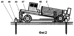
In FIG. 2 is a schematic diagram of an installation for directional drilling with a wheeled chassis;
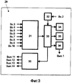
In FIG. 3 shows a diagram of an electronic control system.
Автоматизированный буровой комплекс для прокладки коммуникаций посредством формирования скважины колонной бурильных труб 1 содержит установку для наклонного бурения 2 с кассетой для бурильных труб 3. Установка для наклонного бурения 2 смонтирована на шасси 4 и содержит цилиндр регулятора начального угла бурения 5, насос 6, привод насоса 7, емкость для бурового раствора 8, датчик уровня бурового раствора 9, устройство подачи бурового раствора 10, гибкий шланг подачи бурового раствора 11, лоток для сбора бурового раствора 12, магистраль возврата бурового раствора 13. Автоматизированный буровой комплекс оборудован гидростанцией 14, блоком контроля и управления гидростанцией 15, которая через нагнетательную линию рабочего цилиндра 16 соединена с рабочим цилиндром 17 и нагнетательной линии регулятора начального угла 18 с цилиндром регулятора начального угла 5. Последовательно снизу вверх установлены долото 19, турбобур 20, отклонитель 21 с приводом отклонителя 22, скважинный прибор 23, соединенные с колонной бурильных труб. В схеме автоматизированного, навигационного бурового комплекса применен виброударный механизм 24. Свинчивание труб, входящих в состав колонны бурильных труб 1, осуществляют ключом 25 с приводом ключа 26. В верхней части шасси 4 установлен ротор 27 и привод для проворачивания ротора 28. An automated drilling complex for laying communications through the formation of a borehole with a drill pipe string 1 contains an installation for
Автоматизированный навигационный буровой комплекс содержит электронную систему контроля и управления 29, в состав которой входят устройство управления комплексом 30 и преобразовательный комплекс 31 с аналого-цифровыми преобразователями сигналов от датчиков (на фиг. 1-3 аналого-цифровые преобразователи не показаны), приемное устройство 32, персональный компьютер 33 и монитор 34, принтер 35, блок сопряжения 36. Антенна 37 присоединена к приемному устройству 32. The automated navigation drilling complex contains an electronic monitoring and
Буровой комплекс оборудован наземными датчиками: датчиком давления бурового раствора 38, расходомером 39, датчиком давления в рабочем гидроцилиндре 40, счетчиком труб 41, устройством для измерения длины труб 42 и датчиком угла 43. The drilling complex is equipped with ground sensors: a drilling fluid pressure sensor 38, a flow meter 39, a pressure sensor in the working hydraulic cylinder 40, a pipe counter 41, a device for measuring pipe length 42 and an angle sensor 43.
Возможны варианты исполнения предложенного комплекса в стационарном исполнении (фиг. 1) и с применением шасси 4 на колесном или гусеничном ходу (фиг. 2). There are possible versions of the proposed complex in a stationary version (Fig. 1) and with the use of the chassis 4 on a wheeled or tracked track (Fig. 2).
При исполнении на колесном ходу установка содержит выдвижные опоры 44, якоря 45 с приводами якорей 46, колеса 47, кабину оператора 48. В кабине оператора 48 находится пульт бурильщика 49. When mounted on a wheeled drive, the installation comprises
Работает автоматизированный навигационный буровой комплекс для прокладки коммуникаций следующим образом. При помощи цилиндра регулятора начального угла бурения 5 устанавливают шасси 4 установки для бурения 2 под необходимым углом и производят забуривание входного участка траектории скважины под проектным углом. При помощи ключа 25 с приводом ключа 26 производят наращивание колонны бурильных труб, используя буровые трубы, имеющиеся на кассете для буровых труб 3. Потом осуществляют прокачку бурового раствора по системе подачи бурового раствора из емкости для бурового раствора 8 насосом 6. There is an automated navigation drilling complex for laying communications as follows. Using the cylinder for adjusting the initial angle of drilling 5, the chassis 4 of the installation for
Турбобур 20 вращает долото 19, которое разрушает породу. При помощи рабочего гидроцилиндра 17 создают необходимое осевое давление на колонну бурильных труб 1. При помощи отклонителя 21 с приводом отклонителя 22 изменяют при необходимости кривизну траектории скважины. При прохождении особо твердых пород задействуется виброударный механизм 24, который, создавая осевые вибрации всей колонны бурильных труб 1 и долота 19, значительно увеличивает механическую скорость бурения. Во время работы виброударного механизма срабатывает устройство переключения скважинного прибора в ждущий режим, который обеспечивает экономию расхода электроэнергии батарейного питания. Turbo-drill 20 rotates the bit 19, which destroys the rock. Using the working hydraulic cylinder 17, the necessary axial pressure is created on the drill string 1. Using the diverter 21 with the diverter drive 22, the curvature of the well path is changed if necessary. When passing through particularly hard rocks, a vibro-impact mechanism 24 is activated, which, creating axial vibrations of the entire drill string 1 and bit 19, significantly increases the mechanical drilling speed. During operation of the vibro-shock mechanism, the device for switching the downhole tool to standby mode is activated, which saves battery power.
В процессе бурения осуществляется измерение забойных инклинометрических параметров и технологических параметров при помощи забойной телеметрической системы. Инклинометрические параметры измеряются датчиками (на фиг.1 не показаны), входящими в состав скважинного прибора. Наземные параметры непрерывно регистрируются при помощи датчиков 38, 39, 40, 41, 42, 43. С этих датчиков параметры передаются на преобразовательный комплекс 31 и далее в персональный компьютер 33. В персональном компьютере 33 полученная информация обрабатывается, анализируется и передается в устройство управления комплексом 30, которое выдает сигналы на Вых. 11, 12, 13 и 14, соответственно на вход в блок контроля и управления гидростанцией 15, привод насоса 7, привод ключа 26 и привод ротора 28. During the drilling process, downhole inclinometric parameters and technological parameters are measured using the downhole telemetry system. Inclinometric parameters are measured by sensors (not shown in FIG. 1) included in the downhole tool. Ground parameters are continuously recorded using sensors 38, 39, 40, 41, 42, 43. From these sensors, parameters are transmitted to the
Применение изобретения позволило:
1. Осуществлять бурение под естественными преградами для прокладки коммуникаций под ними.The application of the invention allowed:
1. Drilling under natural barriers for laying communications under them.
2. Управлять траекторией процесса бурения. 2. Manage the trajectory of the drilling process.
3. Полностью автоматизировать процесс управления процессом бурения. 3. Fully automate the process of controlling the drilling process.
4. Эффективно разрушать и продавливать грунт и мягкие породы. 4. Effectively destroy and push soil and soft rock.
5. Обеспечить экологичность процесса бурения. 5. Ensure environmental friendliness of the drilling process.
6. Обеспечить экономичное расходование батарейного питания скважинного прибора. 6. Provide economical use of battery power for the downhole tool.
7. Увеличить время непрерывной работы в автономном режиме скважинного прибора. 7. To increase the time of continuous operation in the autonomous mode of the downhole tool.
Claims (13)
Priority Applications (1)
| Application Number | Priority Date | Filing Date | Title |
|---|---|---|---|
| RU2002113180/03A RU2215874C1 (en) | 2002-05-20 | 2002-05-20 | Automated navigation drilling complex for laying service lines |
Applications Claiming Priority (1)
| Application Number | Priority Date | Filing Date | Title |
|---|---|---|---|
| RU2002113180/03A RU2215874C1 (en) | 2002-05-20 | 2002-05-20 | Automated navigation drilling complex for laying service lines |
Publications (1)
| Publication Number | Publication Date |
|---|---|
| RU2215874C1 true RU2215874C1 (en) | 2003-11-10 |
Family
ID=32027886
Family Applications (1)
| Application Number | Title | Priority Date | Filing Date |
|---|---|---|---|
| RU2002113180/03A RU2215874C1 (en) | 2002-05-20 | 2002-05-20 | Automated navigation drilling complex for laying service lines |
Country Status (1)
| Country | Link |
|---|---|
| RU (1) | RU2215874C1 (en) |
Cited By (1)
| Publication number | Priority date | Publication date | Assignee | Title |
|---|---|---|---|---|
| WO2013103706A1 (en) * | 2012-01-05 | 2013-07-11 | Merlin Technology, Inc. | Directional drilling target steering apparatus and method |
-
2002
- 2002-05-20 RU RU2002113180/03A patent/RU2215874C1/en not_active IP Right Cessation
Non-Patent Citations (2)
| Title |
|---|
| ВОЗДВИЖЕНСКИЙ Б.И. И ДР. Современные способы бурения скважин. - М.: Недра, 1970, с.129, с.143, с.57. МОЛЧАНОВ А.А. Измерение геофизических и технологических параметров в процессе бурения скважин. - М.: Недра, 1983, с.173-184. ВОСКРЕСЕНСКИЙ Ф.Ф. Вибрационное и ударно-вращательное бурение. - М.: Гос. Научно-технич. Изд-во нефтяной и горно-топливной аппаратуры, 1961, с.81-83, рис.67. * |
| МИНАЕВ В.И. Машины для строительства магистральных трубопроводов. - М.: Недра, 1985, с.269-272. * |
Cited By (6)
| Publication number | Priority date | Publication date | Assignee | Title |
|---|---|---|---|---|
| WO2013103706A1 (en) * | 2012-01-05 | 2013-07-11 | Merlin Technology, Inc. | Directional drilling target steering apparatus and method |
| RU2600118C2 (en) * | 2012-01-05 | 2016-10-20 | Мерлин Технолоджи, Инк. | Device and method of target guidance at drilling |
| US9540879B2 (en) | 2012-01-05 | 2017-01-10 | Merlin Technology, Inc. | Directional drilling target steering apparatus and method |
| US10781638B2 (en) | 2012-01-05 | 2020-09-22 | Merlin Technology, Inc. | Directional drilling target steering apparatus and method |
| US11060355B2 (en) | 2012-01-05 | 2021-07-13 | Merlin Technology, Inc. | Directional drilling target steering apparatus and method |
| US11629554B2 (en) | 2012-01-05 | 2023-04-18 | Merlin Technology, Inc. | Directional drilling target steering apparatus and method |
Similar Documents
| Publication | Publication Date | Title |
|---|---|---|
| USRE46090E1 (en) | Method and apparatus for directional drilling | |
| US6155343A (en) | System for cutting materials in wellbores | |
| US8360172B2 (en) | Steering device for downhole tools | |
| CN103703209B (en) | Comprise the brill soil working tool of regracting pad, comprise cylinder for the regracting pad of this instrument and correlation technique | |
| CA2705511C (en) | Apparatus and method for communicating information between a wellbore and surface | |
| US20130000981A1 (en) | Control of downhole safety devices | |
| CA2776610C (en) | Drill bits and methods of drilling curved boreholes | |
| CN103608545A (en) | System, method, and computer program for predicting borehole geometry | |
| NO324567B1 (en) | Process for the production of hydrocarbons from a soil formation | |
| CN103774990A (en) | Method and system for controlling well drilling system for drilling well in earth stratum | |
| US20110061938A1 (en) | Directional well drilling | |
| WO1998017894A2 (en) | Drilling system with integrated bottom hole assembly | |
| WO1998017894A9 (en) | Drilling system with integrated bottom hole assembly | |
| EP3445943B1 (en) | Directional drilling control system and methods | |
| US10697245B2 (en) | Seabed drilling system | |
| CA2268444A1 (en) | Apparatus and method for drilling boreholes | |
| RU2215874C1 (en) | Automated navigation drilling complex for laying service lines | |
| RU25906U1 (en) | AUTOMATED, NAVIGATION DRILLING COMPLEX FOR DRILLING UNDER OBSTACLES | |
| EP0562147A1 (en) | Directional drilling system with eccentric mounted motor and biaxial sensor | |
| AU731454B2 (en) | System for cutting materials in wellbores | |
| Dickinson et al. | Data Acquisition, Analysis, and Control While Drilling with Horizontal Water Jet Drilling Systems | |
| RU218267U1 (en) | Turbine power generator with the ability to explore oil and gas wells | |
| CA2269498C (en) | Drilling system with integrated bottom hole assembly | |
| WO2015005800A1 (en) | Autonomous drilling | |
| Pixton et al. | Advanced mud hammer systems |
Legal Events
| Date | Code | Title | Description |
|---|---|---|---|
| MM4A | The patent is invalid due to non-payment of fees |
Effective date: 20050521 |
|
| NF4A | Reinstatement of patent |
Effective date: 20080227 |
|
| MM4A | The patent is invalid due to non-payment of fees |
Effective date: 20150521 |