RU2208103C1 - Process of mounting of prestressed strutted unit of covering - Google Patents
Process of mounting of prestressed strutted unit of covering Download PDFInfo
- Publication number
- RU2208103C1 RU2208103C1 RU2002121993/03A RU2002121993A RU2208103C1 RU 2208103 C1 RU2208103 C1 RU 2208103C1 RU 2002121993/03 A RU2002121993/03 A RU 2002121993/03A RU 2002121993 A RU2002121993 A RU 2002121993A RU 2208103 C1 RU2208103 C1 RU 2208103C1
- Authority
- RU
- Russia
- Prior art keywords
- tightening
- truss
- prestressed
- covering
- draw bar
- Prior art date
Links
Images
Landscapes
- Reinforcement Elements For Buildings (AREA)
Abstract
Description
Изобретение относится к строительным конструкциям и может быть использовано при изготовлении предварительно напряженных шпренгельных блоков покрытия, применяемых в качестве несущих конструкций покрытий зданий и сооружений и т. п. The invention relates to building structures and can be used in the manufacture of prestressed truss blocks coating used as load-bearing structures of coatings of buildings and structures, etc.
Известен способ предварительного напряжения шпренгельных балок, преимущественно большепролетных покрытий, включающий установку рычагов, присоединение к их средним частям концов затяжки и направляющей со стяжными приспособлениями, к которым прикрепляют одни концы рычагов, подвижно соединенные с направляющей, при этом рычаги выполняют спаренными и соединяют другими концами с предварительно напрягаемой балкой жесткости, а направляющую и концы затяжки размещают между ними, причем концы затяжки жестко закрепляют к рычагам [1]. A known method of prestressing truss beams, mainly large-span coatings, including the installation of levers, connecting to their middle parts of the ends of the tightening and the guide with coupling devices, to which one ends of the levers are movably connected to the guide, while the levers are paired and connected to other ends with a prestressing stiffening beam, and the guide and the ends of the tightening are placed between them, and the ends of the tightening are rigidly fixed to the levers [1].
Недостатком известного технического решения является сложность и трудоемкость его осуществления, связанная с необходимостью монтажа мощных рычагов, направляющих, стяжных приспособлений, а также осуществления прикреплений в местах опирания рычагов на балку жесткости и жесткого закрепления затяжки к рычагам. Кроме того, известное техническое решение предусматривает объединение затяжки при помощи вставки, помещаемой между спаренными рычагами, что также увеличивает трудоемкость процесса предварительного напряжения. A disadvantage of the known technical solution is the complexity and complexity of its implementation, associated with the need to install powerful levers, guides, clamping devices, as well as the implementation of attachments in places of support of the levers on the stiffener beam and tightening the tightening to the levers. In addition, the known technical solution provides for the combination of a puff using an insert placed between paired levers, which also increases the complexity of the pre-stress process.
Также известен способ монтажа предварительно напряженной несущей конструкции, включающий монтаж элемента жесткости, прикрепление к его торцам гибкой затяжки, установку средней стойки шпренгеля, после чего производится первый этап натяжения затяжки домкратами двойного действия, закрепленными на концах гибкой затяжки, а второй этап предварительного натяжения производится посредством удлинения средней стойки шпренгеля, смонтированной на ней винтовой муфтой [2] (принято за прототип). There is also a known method of mounting a prestressed load-bearing structure, including mounting a stiffener, attaching a flexible tightening to its ends, installing a middle strut post, after which the first step of tightening is carried out by double-acting jacks fixed at the ends of the flexible tightening, and the second stage of pre-tensioning is performed by lengthening the middle strut rack mounted on it with a screw coupling [2] (adopted as a prototype).
Недостатком такого технического решения является повышенная трудоемкость, обусловленная необходимостью присоединения к гибкой затяжке и средней стойке шпренгеля натяжных устройств (домкратов и стяжной муфты), а также невозможностью демонтажа стяжной муфты, что, в конечном счете, повышает трудоемкость монтажа конструкции в целом. The disadvantage of this technical solution is the increased complexity due to the need to connect tensioning devices (jacks and a shrink sleeve) to the flexible tightening and the middle strut rack, as well as the inability to dismantle the shrink sleeve, which ultimately increases the complexity of mounting the structure as a whole.
Задачей настоящего изобретения является снижение трудоемкости монтажа предварительно напряженных шпренгельных блоков покрытия. The objective of the present invention is to reduce the complexity of installing prestressed truss blocks coating.
Технический результат достигается тем, что в способе монтажа предварительно напряженного шпренгельного блока покрытия, включающем крепление к концам элемента жесткости приопорных хомутов, объединенных затяжкой, и установку диафрагм шпренгеля, приопорные хомуты пропускают в петли на концах затяжки, затем направляющие на концах диафрагм шпренгеля упирают в сегментообразные торцы стопоров затяжки, а ригели диафрагм шпренгеля заводят в криволинейные направляющие элемента жесткости и объединяют их временной затяжкой, снабженной натяжным устройством, с помощью которого смещают ригели диафрагм шпренгеля навстречу друг другу до касания с упорами криволинейных направляющих, после чего устанавливают фиксаторы и демонтируют временную затяжку. The technical result is achieved by the fact that in the method of mounting a prestressed truss coating unit, including attaching the clamps united by a tightening to the ends of the stiffening element and installing the truss diaphragms, the clamps are passed into loops at the ends of the tightening, then the guides at the ends of the truss diaphragms are abutted the ends of the tightening stoppers, and the bolts of the diaphragms of the sprengel lead into the curved guides of the stiffening element and combine them with a temporary tightening provided with a tension m device, by which the diaphragms are displaced crossbars Sprengel toward each other to touch the stop cam rails, whereupon the latches mounted and dismounted temporary tightness.
Предлагаемое техническое решение описывается следующими графическими материалами:
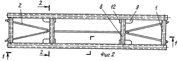
- на фиг. 1 приводится общий вид предварительно напряженного шпренгельнго блока (вид по 1-1 на фиг. 2) после монтажа;
- на фиг. 2 - план шпренгельного блока по фиг. 1;
- на фиг. 3 - поперечный разрез по 2-2 на фиг. 2;
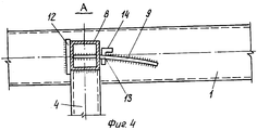
- на фиг. 4 - узел А на фиг. 1;
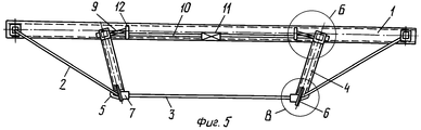
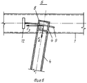
- на фиг. 5 - общий вид предварительно напряженного шпренгельного блока на стадии монтажа;
- на фиг. 6 - узел Б на фиг. 5;
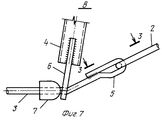
- на фиг. 7 - узел В на фиг. 5;
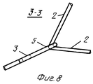
- на фиг. 8 - вид по 3 - 3 на фиг. 7.The proposed technical solution is described by the following graphic materials:
- in FIG. 1 is a general view of a prestressed spreel block (view 1-1 in FIG. 2) after installation;
- in FIG. 2 is a plan of the truss block of FIG. 1;
- in FIG. 3 is a cross section through 2-2 of FIG. 2;
- in FIG. 4 - node A in FIG. 1;
- in FIG. 5 is a general view of a prestressed truss block at the installation stage;
- in FIG. 6 - node B in FIG. 5;
- in FIG. 7 - node B in FIG. 5;
- in FIG. 8 is a view of 3 to 3 in FIG. 7.
Предлагаемый способ монтажа предварительно напряженного шпренгельного блока покрытия заключается в прикреплении к концам элемента жесткости 1 приопорных хомутов 2, объединенных затяжкой усиления 3, и установке диафрагм 4 шпренгеля, для чего приопорные хомуты 2 пропускают в петли 5 на концах затяжки усиления 3 и крепят их к концам элемента жесткости 1 (например, с помощью резьбовых концевиков с гайками), затем направляющие 6 диафрагм 4 шпренгеля упирают в сегментообразные торцы стопоров 7 затяжки усиления 3, а ригели 8 диафрагм 4 шпренгеля, снабженные прорезями на концах, заводят в криволинейные направляющие 9 элемента жесткости 1 и объединяют их временной затяжкой 10 с натяжным устройством 11 (например, стяжной муфтой), при помощи которого затем смещают ригели 8 диафрагм 4 шпренгеля навстречу друг другу до касания с упорами 12 криволинейных направляющих 9, в результате чего диафрагмы 4 шпренгеля поворачиваются относительно точек упора направляющих 6 диафрагм 4 шпренгеля в стопоры 7 затяжки 3, после чего в отверстия 13 криволинейных направляющих 9 устанавливают фиксаторы 14 и демонтируют временную затяжку 10. The proposed method of mounting a prestressed truss coating unit consists in attaching to the ends of the stiffening
На концах затяжки 3 устроены петли 5 и стопоры 7, например, в виде спрессованных шайб. At the ends of the
Закрепление временной затяжки 10 к ригелям 8 диафрагм 4 шпренгеля осуществляется, например, с использованием торцевых анкеров. The fastening of the
При стягивании натяжным устройством 11 временной затяжки 10 она укорачивается, что приводит к перемещению ригелей 8 диафрагм 4 шпренгеля навстречу друг другу (в направлении к середине пролета), при этом ригели 8 перемещаются в направляющих 9 (например, листового типа) вплоть до касания с упорами 12. When the
При перемещении диафрагм 4 шпренгеля из начального наклонного положения в проектное расстояние между осями элемента жесткости 1 и затяжки 3 увеличивается, что приводит к появлению в затяжке 3 и приопорных хомутах 2 растягивающих усилий предварительного напряжения. When moving the
Стопоры 7 с сегментообразными торцами, смонтированные на затяжке 3, предотвращают смещение направляющих 6 диафрагм 4 шпренгеля и соответственно нижних концов диафрагм 4 шпренгеля, фиксируя их положение в процессе напряжения временной затяжки 10 натяжным устройством 11. При этом на стопоры 7 воздействуют усилия, возникающие из-за разности горизонтальных составляющих усилий в затяжке 3 и приопорных хомутах 2. The
Торцы стопоров 7 затяжки 3, контактирующие с направляющими диафрагм 4 шпренгеля, выполнены сегментообразными, что позволяет обеспечить поворот диафрагм 4 шпренгеля относительно их точек упора в стопоры 7 затяжки 3 и уменьшить необходимые усилия для перемещения ригелей 8 диафрагм 4 шпренгеля навстречу друг другу, что, как следствие, приводит к снижению трудоемкости монтажа. The ends of the
Криволинейные направляющие 9 выполнены по кривым, радиус кривизны которых равен расстоянию от направляющей 6 диафрагмы 4 шпренгеля в месте пропуска затяжки 3 до прорезей ригеля 8 диафрагмы 4 шпренгеля, что позволяет уменьшить дополнительные усилия при перемещении ригеля 8 диафрагмы 4 шпренгеля (повороте диафрагм 4 шпренгеля) по направляющим 9 элемента жесткости 1, и, как следствие, снизить трудоемкость монтажа в целом.
При натяжении временной затяжки 10 натяжным устройством 11 диафрагмы 4 шпренгеля поворачиваются и соответственно угол α между продольной осью диафрагмы 4 и осью временной затяжки 10 увеличивается, следовательно, усилия во временной затяжке 10 и натяжном устройстве 11, необходимые для перемещения ригелей 8 диафрагмы 4 шпренгеля и равные Fз=Fд•cosα (где Fз - усилие натяжения во временной затяжке 10, Fд - реакция направляющих 9), уменьшаются, что приводит к снижению трудоемкости процесса предварительного напряжения временной затяжки 10 натяжным устройством 11 и, как следствие, к снижению трудоемкости монтажа всего шпренгельного блока покрытия в целом.When tensioning the
Кроме того, отпадает необходимость в стационарном натяжном устройстве (стяжной муфте и т. п.), которое остается на установленном предварительно напряженном шпренгельном блоке покрытия и в дальнейшем не используется. In addition, there is no need for a stationary tensioner (shrink sleeve, etc.), which remains on the installed prestressed truss cover unit and is not used in the future.
Демонтируемые временная затяжка 10 и натяжное устройство 11 являются инвентарными элементами многократного применения. Dismountable
Использование предлагаемого изобретения позволит снизить трудоемкость монтажа предварительно напряженных шпренгельных блоков покрытия на 10... 15%. Using the proposed invention will reduce the complexity of installing prestressed truss blocks coating by 10 ... 15%.
ИСПОЛЬЗОВАННЫЕ ИСТОЧНИКИ
1. Авторское свидетельство СССР 802479, Е 04 G 21/12; В 1/22. Исаев П.М. и др. Натяжное устройство преимущественно для предварительного напряжения шпренгельных балок большепролетных покрытий. - Бюл. 5. - 1981.USED SOURCES
1. USSR author's certificate 802479, E 04 G 21/12; At 1/22. Isaev P.M. and others. Tension device mainly for prestressing truss beams of large-span coatings. - Bull. 5. - 1981.
2. Беленя Е.И. Предварительно напряженные несущие металлические конструкции. -М.: Стройиздат, 1975. - с. 250...252 (рис. V.21). 2. Belena E.I. Pre-stressed load-bearing metal structures. -M.: Stroyizdat, 1975 .-- p. 250 ... 252 (Fig. V.21).
Claims (1)
Priority Applications (1)
| Application Number | Priority Date | Filing Date | Title |
|---|---|---|---|
| RU2002121993/03A RU2208103C1 (en) | 2002-08-12 | 2002-08-12 | Process of mounting of prestressed strutted unit of covering |
Applications Claiming Priority (1)
| Application Number | Priority Date | Filing Date | Title |
|---|---|---|---|
| RU2002121993/03A RU2208103C1 (en) | 2002-08-12 | 2002-08-12 | Process of mounting of prestressed strutted unit of covering |
Publications (1)
| Publication Number | Publication Date |
|---|---|
| RU2208103C1 true RU2208103C1 (en) | 2003-07-10 |
Family
ID=29212228
Family Applications (1)
| Application Number | Title | Priority Date | Filing Date |
|---|---|---|---|
| RU2002121993/03A RU2208103C1 (en) | 2002-08-12 | 2002-08-12 | Process of mounting of prestressed strutted unit of covering |
Country Status (1)
| Country | Link |
|---|---|
| RU (1) | RU2208103C1 (en) |
Citations (3)
| Publication number | Priority date | Publication date | Assignee | Title |
|---|---|---|---|---|
| US4353190A (en) * | 1979-03-02 | 1982-10-12 | Gleeson Maurice J | Stiffened elongate support member |
| GB2174430A (en) * | 1985-05-04 | 1986-11-05 | Tartan Buildings Limited | Improvements in and relating to a beam for use in buildings |
| SU1308731A1 (en) * | 1985-04-29 | 1987-05-07 | Липецкий политехнический институт | Method of mounting prestrained combination system |
-
2002
- 2002-08-12 RU RU2002121993/03A patent/RU2208103C1/en not_active IP Right Cessation
Patent Citations (3)
| Publication number | Priority date | Publication date | Assignee | Title |
|---|---|---|---|---|
| US4353190A (en) * | 1979-03-02 | 1982-10-12 | Gleeson Maurice J | Stiffened elongate support member |
| SU1308731A1 (en) * | 1985-04-29 | 1987-05-07 | Липецкий политехнический институт | Method of mounting prestrained combination system |
| GB2174430A (en) * | 1985-05-04 | 1986-11-05 | Tartan Buildings Limited | Improvements in and relating to a beam for use in buildings |
Non-Patent Citations (1)
| Title |
|---|
| БЕЛЕНЯ Е.И. Предварительно напряженные несущие металлические конструкции. - М.: Стройиздат, 1975, с.250-252, (рис.V.21). * |
Similar Documents
| Publication | Publication Date | Title |
|---|---|---|
| US6513287B1 (en) | Apparatus for forming a dead-end anchorage of a post-tension system | |
| US4607470A (en) | Pre-stressed construction element | |
| RU2208103C1 (en) | Process of mounting of prestressed strutted unit of covering | |
| KR970070374A (en) | Installation method of precast concrete beam | |
| JP3049143B2 (en) | Large span frame structure and construction method thereof | |
| KR101642103B1 (en) | Cable Wall System using Reinforced Concrete Fixture | |
| JP2003138523A (en) | Construction method for tension string girder bridge | |
| JP3055081B2 (en) | How to fix tension material | |
| RU2188915C1 (en) | Method of installation of prestressed strutted frame | |
| KR20140088472A (en) | Thermal prestressed girder of temporary structures controlled by adjust tendon and manufacturing method of the same | |
| RU2280133C1 (en) | Method for beam reinforcement with subdiagonal | |
| RU2187608C1 (en) | Way of reinforcement of beam by pre-stressed strut frame | |
| CN219753557U (en) | Earthquake-resistant mechanism for housing construction | |
| JPH01268947A (en) | Beam with reinforced concrete end and steel central structure | |
| SU1761885A2 (en) | Method of erecting multistory building | |
| NL1011695C1 (en) | Floor support construction, comprises tensile reinforcing rods made from soft steel | |
| RU2190735C1 (en) | Method for combination prestressing of perforated trussed beam | |
| RU2344224C2 (en) | Combined suspended structure | |
| JPH11182633A (en) | Cable tension applying device and cable stretching method | |
| JP2601752B2 (en) | Curved type frame | |
| RU2208104C1 (en) | Process of mounting of prestressed strutframed beam | |
| JPH08158478A (en) | Arch construction method | |
| JPH0441733B2 (en) | ||
| RU2344225C2 (en) | Combined suspended structure | |
| KR101630112B1 (en) | Damage Minimizing Anchorage for Existing Structures and its application for Post-Tensioning Method |
Legal Events
| Date | Code | Title | Description |
|---|---|---|---|
| MM4A | The patent is invalid due to non-payment of fees |
Effective date: 20040813 |