RU2207902C2 - Shaped packing element - Google Patents
Shaped packing element Download PDFInfo
- Publication number
- RU2207902C2 RU2207902C2 RU2001107963/12A RU2001107963A RU2207902C2 RU 2207902 C2 RU2207902 C2 RU 2207902C2 RU 2001107963/12 A RU2001107963/12 A RU 2001107963/12A RU 2001107963 A RU2001107963 A RU 2001107963A RU 2207902 C2 RU2207902 C2 RU 2207902C2
- Authority
- RU
- Russia
- Prior art keywords
- chords
- elements
- element according
- nozzle element
- cylindrical body
- Prior art date
Links
- 238000012856 packing Methods 0.000 title abstract description 11
- 238000005192 partition Methods 0.000 claims description 8
- 230000003014 reinforcing effect Effects 0.000 claims description 7
- 230000004323 axial length Effects 0.000 claims description 4
- 229910010293 ceramic material Inorganic materials 0.000 claims description 3
- OKTJSMMVPCPJKN-UHFFFAOYSA-N Carbon Chemical compound [C] OKTJSMMVPCPJKN-UHFFFAOYSA-N 0.000 claims 1
- 229910052799 carbon Inorganic materials 0.000 claims 1
- 239000002184 metal Substances 0.000 claims 1
- 239000007788 liquid Substances 0.000 abstract description 4
- 230000007797 corrosion Effects 0.000 abstract 1
- 238000005260 corrosion Methods 0.000 abstract 1
- 230000000694 effects Effects 0.000 abstract 1
- 230000002708 enhancing effect Effects 0.000 abstract 1
- 239000000126 substance Substances 0.000 abstract 1
- 238000001125 extrusion Methods 0.000 description 4
- 239000000919 ceramic Substances 0.000 description 3
- 239000007789 gas Substances 0.000 description 3
- 238000000034 method Methods 0.000 description 3
- 230000001788 irregular Effects 0.000 description 2
- 238000001311 chemical methods and process Methods 0.000 description 1
- 230000006835 compression Effects 0.000 description 1
- 238000007906 compression Methods 0.000 description 1
- 238000004090 dissolution Methods 0.000 description 1
- 238000005516 engineering process Methods 0.000 description 1
- 239000012530 fluid Substances 0.000 description 1
- 238000004519 manufacturing process Methods 0.000 description 1
- 239000000463 material Substances 0.000 description 1
- 238000000465 moulding Methods 0.000 description 1
- 238000000926 separation method Methods 0.000 description 1
- 239000000725 suspension Substances 0.000 description 1
Images
Classifications
-
- B—PERFORMING OPERATIONS; TRANSPORTING
- B01—PHYSICAL OR CHEMICAL PROCESSES OR APPARATUS IN GENERAL
- B01J—CHEMICAL OR PHYSICAL PROCESSES, e.g. CATALYSIS OR COLLOID CHEMISTRY; THEIR RELEVANT APPARATUS
- B01J19/00—Chemical, physical or physico-chemical processes in general; Their relevant apparatus
- B01J19/30—Loose or shaped packing elements, e.g. Raschig rings or Berl saddles, for pouring into the apparatus for mass or heat transfer
-
- B—PERFORMING OPERATIONS; TRANSPORTING
- B01—PHYSICAL OR CHEMICAL PROCESSES OR APPARATUS IN GENERAL
- B01D—SEPARATION
- B01D47/00—Separating dispersed particles from gases, air or vapours by liquid as separating agent
- B01D47/14—Packed scrubbers
-
- B—PERFORMING OPERATIONS; TRANSPORTING
- B01—PHYSICAL OR CHEMICAL PROCESSES OR APPARATUS IN GENERAL
- B01D—SEPARATION
- B01D53/00—Separation of gases or vapours; Recovering vapours of volatile solvents from gases; Chemical or biological purification of waste gases, e.g. engine exhaust gases, smoke, fumes, flue gases, aerosols
- B01D53/14—Separation of gases or vapours; Recovering vapours of volatile solvents from gases; Chemical or biological purification of waste gases, e.g. engine exhaust gases, smoke, fumes, flue gases, aerosols by absorption
- B01D53/18—Absorbing units; Liquid distributors therefor
-
- B—PERFORMING OPERATIONS; TRANSPORTING
- B01—PHYSICAL OR CHEMICAL PROCESSES OR APPARATUS IN GENERAL
- B01J—CHEMICAL OR PHYSICAL PROCESSES, e.g. CATALYSIS OR COLLOID CHEMISTRY; THEIR RELEVANT APPARATUS
- B01J2219/00—Chemical, physical or physico-chemical processes in general; Their relevant apparatus
- B01J2219/30—Details relating to random packing elements
- B01J2219/302—Basic shape of the elements
- B01J2219/30223—Cylinder
-
- B—PERFORMING OPERATIONS; TRANSPORTING
- B01—PHYSICAL OR CHEMICAL PROCESSES OR APPARATUS IN GENERAL
- B01J—CHEMICAL OR PHYSICAL PROCESSES, e.g. CATALYSIS OR COLLOID CHEMISTRY; THEIR RELEVANT APPARATUS
- B01J2219/00—Chemical, physical or physico-chemical processes in general; Their relevant apparatus
- B01J2219/30—Details relating to random packing elements
- B01J2219/304—Composition or microstructure of the elements
- B01J2219/30416—Ceramic
-
- B—PERFORMING OPERATIONS; TRANSPORTING
- B01—PHYSICAL OR CHEMICAL PROCESSES OR APPARATUS IN GENERAL
- B01J—CHEMICAL OR PHYSICAL PROCESSES, e.g. CATALYSIS OR COLLOID CHEMISTRY; THEIR RELEVANT APPARATUS
- B01J2219/00—Chemical, physical or physico-chemical processes in general; Their relevant apparatus
- B01J2219/30—Details relating to random packing elements
- B01J2219/304—Composition or microstructure of the elements
- B01J2219/30466—Plastics
-
- B—PERFORMING OPERATIONS; TRANSPORTING
- B01—PHYSICAL OR CHEMICAL PROCESSES OR APPARATUS IN GENERAL
- B01J—CHEMICAL OR PHYSICAL PROCESSES, e.g. CATALYSIS OR COLLOID CHEMISTRY; THEIR RELEVANT APPARATUS
- B01J2219/00—Chemical, physical or physico-chemical processes in general; Their relevant apparatus
- B01J2219/30—Details relating to random packing elements
- B01J2219/318—Manufacturing aspects
- B01J2219/3188—Extruding
-
- Y—GENERAL TAGGING OF NEW TECHNOLOGICAL DEVELOPMENTS; GENERAL TAGGING OF CROSS-SECTIONAL TECHNOLOGIES SPANNING OVER SEVERAL SECTIONS OF THE IPC; TECHNICAL SUBJECTS COVERED BY FORMER USPC CROSS-REFERENCE ART COLLECTIONS [XRACs] AND DIGESTS
- Y10—TECHNICAL SUBJECTS COVERED BY FORMER USPC
- Y10S—TECHNICAL SUBJECTS COVERED BY FORMER USPC CROSS-REFERENCE ART COLLECTIONS [XRACs] AND DIGESTS
- Y10S261/00—Gas and liquid contact apparatus
- Y10S261/72—Packing elements
-
- Y—GENERAL TAGGING OF NEW TECHNOLOGICAL DEVELOPMENTS; GENERAL TAGGING OF CROSS-SECTIONAL TECHNOLOGIES SPANNING OVER SEVERAL SECTIONS OF THE IPC; TECHNICAL SUBJECTS COVERED BY FORMER USPC CROSS-REFERENCE ART COLLECTIONS [XRACs] AND DIGESTS
- Y10—TECHNICAL SUBJECTS COVERED BY FORMER USPC
- Y10T—TECHNICAL SUBJECTS COVERED BY FORMER US CLASSIFICATION
- Y10T428/00—Stock material or miscellaneous articles
- Y10T428/29—Coated or structually defined flake, particle, cell, strand, strand portion, rod, filament, macroscopic fiber or mass thereof
- Y10T428/2913—Rod, strand, filament or fiber
- Y10T428/2973—Particular cross section
Abstract
Description
Изобретение имеет отношение к созданию фасонных насадочных элементов (элементов насадки), в частности фасонных насадочных элементов, выдавленных (отпрессованных) из экструдируемых материалов, таких как пластмассовые или керамические суспензии. The invention relates to the creation of shaped nozzle elements (nozzle elements), in particular shaped nozzle elements extruded (pressed) from extrudable materials, such as plastic or ceramic suspensions.
Такие элементы используют в реакционных аппаратах (реакторах), в которых жидкости и газы вступают в контакт для осуществления реакции, теплопередачи и операций растворения за счет близкого контактирования двух протекающих флюидов. Указанные элементы должны быть спроектированы таким образом, чтобы иметь максимальную площадь поверхности при сохранении размерной стабильности, так чтобы они не сминались и не разрушались при их использовании. Кроме того, в том случае, когда среда, в которой элементы должны работать, является коррозионной и/или находится при повышенной температуре, тогда желательно формовать указанные элементы из керамического материала. Наконец, желательно иметь такую конструкцию элементов, которая проста в массовом производстве при использовании стандартных технологий. Such elements are used in reaction apparatus (reactors) in which liquids and gases come into contact for the implementation of the reaction, heat transfer and dissolution operations due to the close contact of two flowing fluids. These elements should be designed in such a way as to have a maximum surface area while maintaining dimensional stability, so that they do not crumple and do not collapse when used. In addition, in the case where the environment in which the elements are to be operated is corrosive and / or is at elevated temperature, then it is desirable to mold said elements from a ceramic material. Finally, it is desirable to have a design of elements that is easy to mass production using standard technologies.
В соответствии с настоящим изобретением предлагается фасонный насадочный элемент, обладающий высокой прочностью и большой площадью поверхности, который легко может быть изготовлен при помощи простого экструзионного процесса. In accordance with the present invention, there is provided a shaped packing member having high strength and large surface area, which can easily be manufactured using a simple extrusion process.
В соответствии с настоящим изобретением предлагается экструдируемый насадочный элемент, имеющий цилиндрический корпус с постоянным поперечным сечением, который имеет множество хорд, выполненных таким образом, что каждый конец хорды соединен с концом другой хорды, а также имеет множество радиальных перегородок, идущих от оси цилиндра по меньшей мере до средней точки хорды. In accordance with the present invention, there is provided an extrudable packing element having a cylindrical body with a constant cross-section, which has a plurality of chords made in such a way that each end of the chord is connected to the end of the other chord, and also has many radial partitions extending from the cylinder axis at least least to the midpoint of the chord.
Следует иметь в виду, что для простоты внутренняя структура элементов в соответствии с настоящим изобретением, которые являются однородными вдоль осевой длины элемента, описана при помощи характеристик, которые имеются в поперечном сечении элемента, в средней точке его осевой длины. Таким образом, деталь, которая отделяет сегмент внутренней поверхности цилиндра, именуется здесь "хордой", несмотря на то, что этот термин обычно используют в применении к линии внутри круга, которая не проходит через его центр. It should be borne in mind that for simplicity, the internal structure of the elements in accordance with the present invention, which are uniform along the axial length of the element, is described using the characteristics that are present in the cross section of the element at the midpoint of its axial length. Thus, the part that separates the segment of the inner surface of the cylinder is here referred to as the “chord", although this term is usually used to refer to a line inside a circle that does not pass through its center.
Хорды преимущественно имеют одинаковую длину, так как это ведет к большей симметрии и однородности размеров сквозных каналов, образованных с помощью хорд внутри цилиндрического корпуса. Chords mainly have the same length, since this leads to greater symmetry and uniformity in the size of the through channels formed by chords inside the cylindrical body.
Элемент может иметь любое желательное число хорд, а именно от 3 (главным образом при выполнении условия соединения концов хорд друг с другом) до 18 и более. Однако обычно число хорд составляет от 4 до 10, а преимущественно равно 6. В наиболее предпочтительном варианте конструкции 6 хорд сгруппированы в две группы по 3 хорды, причем каждая группа образует равносторонний треугольник, при этом один из указанных треугольников смещен от другого на угол 60o вдоль окружности цилиндрического корпуса.An element can have any desired number of chords, namely from 3 (mainly when the condition for connecting the ends of the chords to each other is satisfied) to 18 or more. However, usually the number of chords is from 4 to 10, and is mostly 6. In the most preferred embodiment, 6 chords are grouped into two groups of 3 chords, each group forming an equilateral triangle, while one of these triangles is offset from the other by an angle of 60 o along the circumference of a cylindrical body.
Число радиальных перегородок определяется в зависимости от числа хорд и должно быть равно числу хорд. Например, если используют 6 хорд, то и число перегородок равно 6. The number of radial partitions is determined depending on the number of chords and should be equal to the number of chords. For example, if you use 6 chords, then the number of partitions is 6.
В соответствии с предпочтительным вариантом предусмотрены дополнительные упрочняющие элементы внутренней поверхности цилиндрического корпуса, которые идут по радиусам от цилиндрического корпуса по меньшей мере до точки пересечения двух хорд. Обычно упрочняющие элементы не доходят до оси конструкции. Легко понять, что такое расположение упрочняющих элементов возможно только при использовании 2 или 3 групп хорд с одинаковым числом хорд (3 или 4) в каждой группе, причем полученные из хорд треугольники или квадраты должны перекрываться и должны быть смещены по окружности цилиндрического корпуса. According to a preferred embodiment, additional reinforcing elements of the inner surface of the cylindrical body are provided, which extend radially from the cylindrical body at least to the intersection point of the two chords. Usually reinforcing elements do not reach the axis of the structure. It is easy to understand that such an arrangement of reinforcing elements is possible only when using 2 or 3 groups of chords with the same number of chords (3 or 4) in each group, and the triangles or squares obtained from the chords must overlap and must be shifted around the circumference of the cylindrical body.
Конструкция в соответствии с настоящим изобретением является весьма эффективной в том смысле, что в ней имеется множество точек пересечения, в которых встречаются жидкости, протекающие вдоль различных поверхностей, причем указанные жидкости вынуждены перемешиваться и сливаться вместе перед последующим новым разделением, что способствует достижению однородности. The structure in accordance with the present invention is very effective in the sense that there are many intersection points at which there are liquids flowing along different surfaces, and these liquids are forced to mix and merge together before the next new separation, which helps to achieve uniformity.
Дополнительное преимущество заключается в том, что все элементы конструкции взаимно упрочняют друг друга. Цилиндрический корпус без внутренних элементов имел бы намного меньшее сопротивление силам сжатия. Хорды, в особенности при использовании 6 хорд, образующих 2 группы, обеспечивают существенное повышение внутренней прочности, которая дополнительно усиливается за счет радиальных перегородок, которые дополнительно скрепляют хорды и предотвращают их деформации. Наконец, дополнительные упрочняющие элементы обеспечивают окончательный уровень упрочнения цилиндрического корпуса. An additional advantage is that all structural elements mutually reinforce each other. A cylindrical housing without internal elements would have much less resistance to compression forces. Chords, especially when using 6 chords forming 2 groups, provide a significant increase in internal strength, which is further enhanced by radial partitions, which additionally hold the chords together and prevent their deformation. Finally, additional reinforcing elements provide the final level of hardening of the cylindrical body.
В том случае, когда хорды образуют две группы по 3 хорды, что является наиболее предпочтительным вариантом, различные упрочняющие элементы делят внутренний объем цилиндрического тела на главным образом равные доли (отсеки). Следовательно, за счет этого кроме упрочнения цилиндрического тела существенно возрастает площадь поверхности, а сопротивление газовому потоку через элемент сводится к минимуму и распределяется таким образом, что во всех каналах элемента имеются одинаковые газовые потоки. In the case when the chords form two groups of 3 chords, which is the most preferred option, various reinforcing elements divide the internal volume of the cylindrical body into mainly equal parts (compartments). Therefore, due to this, in addition to hardening the cylindrical body, the surface area increases significantly, and the resistance to gas flow through the element is minimized and distributed in such a way that all the element channels have the same gas flows.
Цилиндрические элементы в соответствии с настоящим изобретением преимущественно имеют изогнутые торцевые поверхности, что препятствует вводу элементов друг в друга при их использовании в насадке колонны. Изгиб каждой из торцевых поверхностей может быть одинаковым или различным, причем, например, один из концов может быть выпуклым, а другой вогнутым, или же оба конца могут быть выпуклыми или вогнутыми. Однако преимущественно радиус кривизны каждого изогнутого конца является одним и тем же. Такая конфигурация является особенно предпочтительной, так как при экструзии продукта и разрезке экструдата на отдельные элементы единственный дуговой разрез образует вогнутый конец первого элемента и выпуклый конец другого элемента при разделении элементов друг от друга по этому разрезу. Следовательно, при наличии всего двух режущих лезвий или даже одного двустороннего лезвия возможно выполнять все возможные выпуклые и вогнутые комбинации. The cylindrical elements in accordance with the present invention mainly have curved end surfaces, which prevents the entry of elements into each other when they are used in the nozzle of the column. The bend of each of the end surfaces may be the same or different, for example, one of the ends may be convex and the other concave, or both ends may be convex or concave. However, predominantly the radius of curvature of each curved end is one and the same. This configuration is particularly preferred since when the product is extruded and the extrudate is cut into separate elements, a single arc section forms the concave end of the first element and the convex end of the other element when the elements are separated from each other along this section. Therefore, with only two cutting blades or even one double-sided blade, it is possible to carry out all possible convex and concave combinations.
Элементы могут быть изготовлены при помощи процесса формования, но преимущественно они изготовлены при помощи процесса экструзии с использованием специальных экструзионных головок. В результате экструзии получают длинный цилиндр с внутренней структурой, одинаковой по всей его длине. Затем длинный цилиндр разрезают на элементы желательной длины при помощи ножа с изогнутым лезвием, причем полученные элементы будут иметь изогнутые концы, если использован нож с изогнутым лезвием. После этого элементы обжигают в обжиговой печи, в результате чего получают готовые насадочные элементы. Elements can be made using the molding process, but they are mainly made using the extrusion process using special extrusion heads. As a result of extrusion, a long cylinder is obtained with an internal structure that is the same along its entire length. Then the long cylinder is cut into elements of the desired length using a knife with a curved blade, and the resulting elements will have curved ends if a knife with a curved blade is used. After that, the elements are fired in a kiln, resulting in a finished nozzle elements.
Указанные ранее и другие характеристики изобретения будут более ясны из последующего детального описания, данного в качестве примера, не имеющего ограничительного характера и приведенного со ссылкой на сопроводительные чертежи. The above and other characteristics of the invention will be more apparent from the following detailed description, given by way of example, not of a limiting nature and given with reference to the accompanying drawings.
На фиг. 1 показано поперечное сечение, нормальное к оси элемента, выполненного в соответствии с настоящим изобретением. In FIG. 1 shows a cross section normal to the axis of an element made in accordance with the present invention.
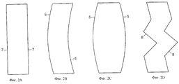
На фиг. 2 показаны четыре возможных вида сбоку (A, B, C и D) элемента фиг.1, который имеет концы с изогнутыми или неправильными поверхностями. In FIG. 2 shows four possible side views (A, B, C and D) of an element of FIG. 1, which has ends with curved or irregular surfaces.
На фиг. 1 показан элемент 1 с цилиндрическим корпусом, который имеет 6 идентичных хорд 2, подразделенных на 2 группы в виде равносторонних треугольников, причем вершины одного из треугольников смещены вдоль окружности корпуса на 60o относительно вершин другого из треугольников. Радиальные перегородки 3 идут от оси до средних точек хорд, а упрочняющие элементы 4 соединяют внутреннюю поверхность цилиндрического корпуса с точками пересечений хорд.In FIG. 1 shows an
На фиг.2 показан вид сбоку элемента фиг.1, причем видны конфигурации концов элемента. Эти концы могут быть соответственно прямыми (7 на фиг.2A), изогнутыми выпуклыми и вогнутыми (соответственно 5 и 6 на фиг.2B); двойными выпуклыми (5 на фиг.2C) и неправильными (8 на фиг.2D). Figure 2 shows a side view of the element of figure 1, and visible configurations of the ends of the element. These ends can be respectively straight (7 in FIG. 2A), curved convex and concave (5 and 6 in FIG. 2B, respectively); double convex (5 in FIG. 2C) and irregular (8 in FIG. 2D).
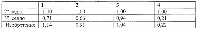
Элементы в соответствии с настоящим изобретением, имеющие конфигурацию, которая показана на фиг.1 и 2В, и изготовленные из керамических материалов, были оценены: (1) по эффективности массопереноса (kga), (2) по степени уплотнения (упаковки) насадки, (3) по весу в фунтах на кубический фут (который свидетельствует об относительном весе насадки) и (4) по числу деталей (элементов насадки) на кубический фут. В каждом случае результат выражали в относительных единицах, при сравнении с промышленным стандартом, равным "1,00", за который было принято керамическое контактное седло, которое может быть закуплено на фирме Norton Chemical Process Products Corporation и имеет зарегистрированный товарный знак "Intalox" (2"). Другой основой для сравнения служило керамическое контактное седло Intalox® (3").Elements in accordance with the present invention, having the configuration shown in FIGS. 1 and 2B, and made of ceramic materials, were evaluated: (1) for mass transfer efficiency (k g a), (2) for the degree of packing (packing) of the nozzle , (3) by weight in pounds per cubic foot (which indicates the relative weight of the nozzle) and (4) by the number of parts (nozzle elements) per cubic foot. In each case, the result was expressed in relative units, when compared with the industry standard of "1.00" for which a ceramic contact seat was adopted, which can be purchased from Norton Chemical Process Products Corporation and has the registered trademark "Intalox" ( 2 "). Another basis for comparison was the Intalox ® ceramic contact seat (3").
Элемент в соответствии с настоящим изобретением имел диаметр 4,25" и толщину от 0,25" (цилиндрический корпусной элемент) до 0,125" (радиальные перегородки). Осевая длина элемента составляла 1,25". The element in accordance with the present invention had a diameter of 4.25 "and a thickness of 0.25" (cylindrical housing element) to 0.125 "(radial partitions). The axial length of the element was 1.25".
Качественные характеристики элементов приведены в таблице, где (1) эффективность массопереноса, (2) степень уплотнения (упаковки) насадки, (3) вес в фунтах на кубический фут и (4) число деталей (элементов насадки) на кубический фут. Qualitative characteristics of the elements are given in the table, where (1) mass transfer efficiency, (2) degree of packing packing (packing), (3) weight in pounds per cubic foot and (4) number of parts (packing elements) per cubic foot.
Из приведенных данных следует, что элементы в соответствии с настоящим изобретением имеют эффективность массопереноса на 14% выше по сравнению с 2" седлами и на 60% по сравнению с 3" седлами. Кроме того, использовано меньше элементов насадки на кубический фут по сравнению с 2" седлами и приблизительно такое же число элементов по сравнению с 3" седлами, при меньшем падении давления по сравнению с 2" седлами. From the above data it follows that the elements in accordance with the present invention have a mass transfer efficiency of 14% higher compared to 2 "seats and 60% compared to 3" saddles. In addition, fewer nozzle elements per cubic foot were used compared to 2 "saddles and about the same number of elements compared to 3" saddles, with a lower pressure drop compared to 2 "saddles.
Claims (8)
Applications Claiming Priority (2)
| Application Number | Priority Date | Filing Date | Title |
|---|---|---|---|
| US09/158,931 | 1998-09-22 | ||
| US09/158,931 US6007915A (en) | 1998-09-22 | 1998-09-22 | Shaped packing element |
Publications (2)
| Publication Number | Publication Date |
|---|---|
| RU2001107963A RU2001107963A (en) | 2003-03-10 |
| RU2207902C2 true RU2207902C2 (en) | 2003-07-10 |
Family
ID=22570332
Family Applications (1)
| Application Number | Title | Priority Date | Filing Date |
|---|---|---|---|
| RU2001107963/12A RU2207902C2 (en) | 1998-09-22 | 1999-08-18 | Shaped packing element |
Country Status (16)
| Country | Link |
|---|---|
| US (1) | US6007915A (en) |
| JP (1) | JP3542776B2 (en) |
| KR (1) | KR100448750B1 (en) |
| AT (1) | AT411333B (en) |
| AU (1) | AU755121B2 (en) |
| BR (1) | BR9914041A (en) |
| CA (1) | CA2344874C (en) |
| DE (1) | DE19940887A1 (en) |
| FR (1) | FR2786410B1 (en) |
| GB (1) | GB2341810B (en) |
| IT (1) | IT1313529B1 (en) |
| RU (1) | RU2207902C2 (en) |
| SE (1) | SE519681C2 (en) |
| TW (1) | TW464528B (en) |
| WO (1) | WO2000017428A1 (en) |
| ZA (1) | ZA200101716B (en) |
Families Citing this family (22)
| Publication number | Priority date | Publication date | Assignee | Title |
|---|---|---|---|---|
| US6193786B1 (en) * | 1998-12-11 | 2001-02-27 | Pacific Gas And Electric Company | Portable oil degasification apparatus |
| US6699562B2 (en) * | 2002-02-28 | 2004-03-02 | Saint-Gobain Corporation | Ceramic packing element |
| US20040170804A1 (en) * | 2002-02-28 | 2004-09-02 | Niknafs Hassan S. | Ceramic packing element with enlarged fluid flow passages |
| US20040166284A1 (en) * | 2002-02-28 | 2004-08-26 | Saint-Gobain Ceramics & Plastics, Inc. | Ceramic packing element for mass transfer applications |
| TW592799B (en) * | 2002-02-28 | 2004-06-21 | Saint Gobain Norpro Corp | Improved ceramic packing element |
| US20030232172A1 (en) * | 2002-06-12 | 2003-12-18 | Niknafs Hassan S. | Ceramic packing element |
| DE10231217B4 (en) * | 2002-07-03 | 2005-12-22 | Arno Stöhr | Filling and / or vegetation body made of plastic |
| US6666436B1 (en) | 2002-09-25 | 2003-12-23 | Beco Engineering Co. | Mixed-size packed beds |
| US7566428B2 (en) * | 2005-03-11 | 2009-07-28 | Saint-Gobain Ceramics & Plastics, Inc. | Bed support media |
| US20060204414A1 (en) * | 2005-03-11 | 2006-09-14 | Saint-Gobain Ceramics & Plastics, Inc. | Bed support media |
| US7722945B2 (en) | 2006-10-10 | 2010-05-25 | Koch-Glitsch, Lp | Random packing elements and column containing same |
| US7862013B2 (en) * | 2006-10-19 | 2011-01-04 | Saint-Gobain Ceramics & Plastics, Inc. | Packing element for use in a chemical processing apparatus |
| EP2107940A4 (en) * | 2007-01-26 | 2012-01-25 | Kenneth Haggerty | Shaped packing element |
| US7775507B2 (en) * | 2007-11-05 | 2010-08-17 | Saint-Gobain Ceramics & Plastics, Inc. | Packing elements for mass transfer applications |
| EP2101134A1 (en) * | 2008-02-28 | 2009-09-16 | Paul Wurth Refractory & Engineering GmbH | Checker brick |
| CN102089074A (en) * | 2008-07-11 | 2011-06-08 | 阿西德管道技术股份有限公司 | Packing element for heat and mass transfer towers |
| US8241717B1 (en) * | 2008-08-20 | 2012-08-14 | SepticNet Inc. | Carbon-based biofilm carrier |
| GB2478587A (en) * | 2010-03-12 | 2011-09-14 | Interpet Ltd | Filter media |
| WO2011149802A2 (en) * | 2010-05-26 | 2011-12-01 | Saint-Gobain Ceramics & Plastics, Inc. | Mass transfer packing element and method of making the same |
| US20150211804A1 (en) * | 2014-01-28 | 2015-07-30 | Kunshan Jue-Chung Electronics Co., Ltd. | Energy storage assembly and energy storage element thereof |
| US10011042B2 (en) * | 2014-03-20 | 2018-07-03 | Robin Crawford | Extruded objects and methods for their manufacture |
| RU210652U1 (en) * | 2022-02-03 | 2022-04-25 | Иван Юрьевич Голованов | NOZZLE ELEMENT |
Family Cites Families (10)
| Publication number | Priority date | Publication date | Assignee | Title |
|---|---|---|---|---|
| US3957931A (en) * | 1970-12-18 | 1976-05-18 | Mass Transfer Limited | Fluid-fluid contact method and apparatus |
| GB1385672A (en) * | 1970-12-18 | 1975-02-26 | Mass Transfer Ltd | Fluid-fluid contact apparatus |
| GB1439745A (en) * | 1972-05-23 | 1976-06-16 | Hydronyl Ltd | Biological filter packing element |
| US4511519A (en) * | 1984-04-30 | 1985-04-16 | Norton Company | Tower packing elements |
| US5498376A (en) * | 1993-11-03 | 1996-03-12 | Lantec Products, Inc. | Packing |
| DE4419114A1 (en) * | 1994-06-01 | 1995-12-07 | Sgl Technik Gmbh | Carbon filling and distribution bodies for flowing fluids |
| EP0764462B1 (en) * | 1995-08-24 | 2000-03-01 | Raschig GmbH | Random packing, in particular for mass and/or heat exchange columns or towers |
| US5690819A (en) * | 1996-07-16 | 1997-11-25 | Chianh; Yung Huang | Structure of biochemical filter ball |
| US5688444A (en) * | 1996-07-29 | 1997-11-18 | Norton Chemcial Process Products Corporation | Tower packing element |
| US5779886A (en) * | 1996-10-23 | 1998-07-14 | Couture; Real | Media for filtration |
-
1998
- 1998-09-22 US US09/158,931 patent/US6007915A/en not_active Expired - Lifetime
-
1999
- 1999-08-18 WO PCT/US1999/018759 patent/WO2000017428A1/en active IP Right Grant
- 1999-08-18 JP JP2000574323A patent/JP3542776B2/en not_active Expired - Fee Related
- 1999-08-18 CA CA002344874A patent/CA2344874C/en not_active Expired - Fee Related
- 1999-08-18 AU AU55697/99A patent/AU755121B2/en not_active Ceased
- 1999-08-18 RU RU2001107963/12A patent/RU2207902C2/en not_active IP Right Cessation
- 1999-08-18 BR BR9914041-1A patent/BR9914041A/en active Search and Examination
- 1999-08-18 KR KR10-2001-7003630A patent/KR100448750B1/en not_active IP Right Cessation
- 1999-08-27 DE DE19940887A patent/DE19940887A1/en not_active Ceased
- 1999-09-08 SE SE9903173A patent/SE519681C2/en not_active IP Right Cessation
- 1999-09-09 TW TW088115554A patent/TW464528B/en not_active IP Right Cessation
- 1999-09-16 AT AT0158999A patent/AT411333B/en not_active IP Right Cessation
- 1999-09-17 FR FR9911811A patent/FR2786410B1/en not_active Expired - Fee Related
- 1999-09-20 IT IT1999MI001942A patent/IT1313529B1/en active
- 1999-09-22 GB GB9922454A patent/GB2341810B/en not_active Expired - Fee Related
-
2001
- 2001-02-28 ZA ZA200101716A patent/ZA200101716B/en unknown
Non-Patent Citations (1)
| Title |
|---|
| Коган В.Б., Харисов М.А. Оборудование для разделения смесей под вакуумом. - Л.: Машиностроение (Ленинградское отделение), 1976, с. 130-131, рис. IV. 2, в. * |
Also Published As
| Publication number | Publication date |
|---|---|
| KR100448750B1 (en) | 2004-09-18 |
| ATA158999A (en) | 2003-05-15 |
| IT1313529B1 (en) | 2002-07-24 |
| FR2786410B1 (en) | 2002-11-15 |
| ITMI991942A0 (en) | 1999-09-20 |
| CA2344874A1 (en) | 2000-03-30 |
| ITMI991942A1 (en) | 2001-03-20 |
| DE19940887A1 (en) | 2000-04-27 |
| SE9903173L (en) | 2000-03-23 |
| SE519681C2 (en) | 2003-03-25 |
| AU755121B2 (en) | 2002-12-05 |
| GB2341810A (en) | 2000-03-29 |
| AT411333B (en) | 2003-12-29 |
| BR9914041A (en) | 2001-06-19 |
| FR2786410A1 (en) | 2000-06-02 |
| AU5569799A (en) | 2000-04-10 |
| GB9922454D0 (en) | 1999-11-24 |
| GB2341810B (en) | 2000-10-11 |
| WO2000017428A1 (en) | 2000-03-30 |
| JP2003506198A (en) | 2003-02-18 |
| US6007915A (en) | 1999-12-28 |
| ZA200101716B (en) | 2003-02-28 |
| JP3542776B2 (en) | 2004-07-14 |
| CA2344874C (en) | 2005-01-18 |
| SE9903173D0 (en) | 1999-09-08 |
| TW464528B (en) | 2001-11-21 |
| KR20010110292A (en) | 2001-12-12 |
Similar Documents
| Publication | Publication Date | Title |
|---|---|---|
| RU2207902C2 (en) | Shaped packing element | |
| JP2731102B2 (en) | Filling element | |
| US4067936A (en) | Fluid-fluid contact apparatus | |
| EP0163153B1 (en) | Tower packing elements | |
| US20080029201A1 (en) | Ceramic packing element | |
| US7014175B2 (en) | Packing for column | |
| JP4574101B2 (en) | Multi-channel element and its manufacturing method | |
| RU2001107963A (en) | SHAPED FITTING ELEMENT | |
| US7753080B2 (en) | Three-dimensionally intersecting diverter as an inner member for a pipe, barrel or tower | |
| US7637485B2 (en) | Packing for column | |
| AU711580B2 (en) | Tower packing element | |
| JPH0272922A (en) | Small-sized monolith structure, manufacture thereof and extrusion die for said manufacture | |
| MXPA01003024A (en) | Shaped packing element | |
| CN207591877U (en) | Filler and packed tower | |
| RU2148496C1 (en) | Adapter in form of screen shell of revolution made from composite material | |
| CN109569493A (en) | Filler and packed tower |
Legal Events
| Date | Code | Title | Description |
|---|---|---|---|
| MM4A | The patent is invalid due to non-payment of fees |
Effective date: 20090819 |