RU2205347C2 - Method for missile firing and missile guidance system - Google Patents
Method for missile firing and missile guidance system Download PDFInfo
- Publication number
- RU2205347C2 RU2205347C2 RU2001114907/02A RU2001114907A RU2205347C2 RU 2205347 C2 RU2205347 C2 RU 2205347C2 RU 2001114907/02 A RU2001114907/02 A RU 2001114907/02A RU 2001114907 A RU2001114907 A RU 2001114907A RU 2205347 C2 RU2205347 C2 RU 2205347C2
- Authority
- RU
- Russia
- Prior art keywords
- firing
- projectile
- optical
- control system
- condition
- Prior art date
Links
Images


Abstract
Description
Изобретение относится к способам стрельбы управляемыми снарядами и оптическим прицельным приспособлениям систем наведения самодвижущихся снарядов. Оно может быть использовано в системах управляемого оружия, в частности в системах наведения с телеориентацией снаряда в луче лазера. The invention relates to methods of firing guided projectiles and optical sights of guidance systems for self-propelled shells. It can be used in guided weapon systems, in particular in guidance systems with teleorientation of a projectile in a laser beam.
В настоящее время широко известны различные способы стрельбы управляемыми снарядами с элементами оптической связи с наземной аппаратурой управления, например [1], которые предполагают операции запуска снаряда и управление им во время полета с наземной аппаратуры. Недостатком большинства способов является отсутствие унификации при использовании снарядов различных типов, а также низкая автоматизация процесса запуска. Currently, various methods of firing guided projectiles with optical communication elements with ground control equipment are widely known, for example [1], which involve projectile launch operations and their control during flight from ground equipment. The disadvantage of most methods is the lack of unification when using shells of various types, as well as low automation of the launch process.
Также широко известны системы наведения, использующие принцип телеориентации управляемого снаряда в лазерном луче [2-4], состоящие из снаряда, снабженного приемником лазерного излучения, и прицела, состоящего из канала визирования цели и канала наведения, включающего в себя излучатель, модулятор и формирующую панкратическую (с переменным фокусным расстоянием) оптическую систему, обеспечивающую постоянство размера сечения луча наведения на текущей дальности управляемого снаряда, за счет чего достигается постоянство энергетического потенциала и точности канала наведения на всей траектории полета снаряда. Guidance systems using the principle of teleorienting a guided projectile in a laser beam [2-4], consisting of a projectile equipped with a laser radiation receiver, and a sight, consisting of a target sighting channel and a guidance channel, including an emitter, a modulator, and a forming pan-optical, are also widely known. (with variable focal length) an optical system that ensures a constant cross-sectional size of the guidance beam at the current range of the guided projectile, thereby achieving a constant energy sweat the potential and accuracy of the guidance channel over the entire flight path of the projectile.
Из-за того, что информационная ось канала наведения совмещена с линией визирования цели, проблемой для таких систем является их низкая помехозащищенность, включающая в себя вопросы помехоустойчивости оптической линии связи и вопросы скрытности. Due to the fact that the information axis of the guidance channel is combined with the line of sight of the target, a problem for such systems is their low noise immunity, including the noise immunity of the optical communication line and the issues of stealth.
Указанные проблемы решены в оптическом прицеле [5], т.к. его конструкция позволяет производить наведение снаряда на цель с отклонением его от линии визирования (превышением над линией визирования) на начальном участке траектории. These problems are solved in the optical sight [5], because its design allows you to aim the projectile at the target with its deviation from the line of sight (exceeding the line of sight) in the initial section of the trajectory.
Использование известного прицела [5] в системах управления ограничено типом применяемых управляемых снарядов. Указанный прицел отвергает унификацию системы наведения для снарядов с различными баллистическими характеристиками (различными зависимостями текущей дальности снаряда от полетного времени), т. к. не позволяет производить введение и снятие превышения с различными скоростями. Кроме того, механизм введении превышения прицела [5] не позволяет производить введение и снятие превышения с переменной скоростью, т.е. с ускорением, которое необходимо для некоторых типов снарядов. The use of the well-known sight [5] in control systems is limited by the type of guided projectiles used. The specified sight rejects the unification of the guidance system for shells with different ballistic characteristics (different dependences of the current projectile range on flight time), because it does not allow the introduction and removal of excess at different speeds. In addition, the mechanism for introducing excess oversight [5] does not allow the introduction and removal of overshot with variable speed, ie with acceleration, which is necessary for some types of shells.
Наиболее близким по технической сути к предлагаемому изобретению является способ наведения управляемого снаряда, реализованный в системе наведения, описанной в [6]. В системе реализована возможность наведения различных типов снарядов за счет смены временного закона изменения фокусного расстояния оптической системы в зависимости от конкретного типа управляемого снаряда. The closest in technical essence to the present invention is a guided projectile guidance method implemented in the guidance system described in [6]. The system implements the ability to guide various types of shells by changing the temporal law of changing the focal length of the optical system depending on the specific type of guided projectile.
Недостатком известного способа и системы [6], как и [1-4], является слабая помехозащищенность из-за наведения снаряда на цель без отклонения его от линии визирования на начальном участке траектории, как это предусмотрено в прицеле [5]. The disadvantage of this method and system [6], like [1-4], is poor noise immunity due to the projectile pointing at the target without deviating it from the line of sight in the initial portion of the trajectory, as provided for in the sight [5].
Ограничение времени на принятие решения в боевой обстановке (при использовании различных типов снарядов особенно) требует максимальной автоматизации запуска снарядов. Автоматизация также предотвращает потери дорогостоящих снарядов, которые могут происходить в результате преждевременного схода снаряда с пусковой установки (когда система еще не готова к управлению снарядом). В системе [6] в прицеле имеется схема управления оптической системой, а в управляемом снаряде - формирователь признака снаряда по типу баллистических характеристик, которые позволяют автоматически запускать соответствующий конкретному снаряду закон движения элементов панкратической оптической системы. Однако в системе не предусмотрено комплексной системы автоматизации запуска, что также является ее недостатком. Нет анализа нахождения механизмов системы в начальном положении, анализа выхода модулятора на режим. Нет анализа положения пусковой установки (ПУ) и положения механизма превышения в прицеле: положение механизма превышения и положение ПУ должны соответствовать дальности до выбранной цели. (При дальности до цели, не превышающей определенного для каждого типа снаряда критического значения, отклонение не вводится и механизм превышения должен находиться в нулевом исходном положении. ) Нет, наконец, анализа наличия излучения, отсутствие которого при сходе снаряда с ПУ наверняка приведет к потере его управления, а следовательно, к его непредсказуемому полету. Кроме того, при наличии в системе управления (как часто бывает в комплексах вооружения) нескольких ПУ необходимо предварительно произвести назначение установки, с которой производится пуск снаряда. Limiting the time for making decisions in a combat situation (when using various types of shells especially) requires maximum automation of the launch of shells. Automation also prevents the loss of expensive shells that can occur as a result of premature exit of the projectile from the launcher (when the system is not yet ready to control the projectile). In the system [6], in the sight there is a control circuit of the optical system, and in a guided projectile there is a projection indicator of the projectile according to the type of ballistic characteristics that allow you to automatically start the law of motion of elements of the pankratic optical system that corresponds to a specific projectile. However, the system does not provide an integrated launch automation system, which is also its drawback. There is no analysis of finding the mechanisms of the system in the initial position, analysis of the modulator output to the mode. There is no analysis of the position of the launcher (launcher) and the position of the excess mechanism in the sight: the position of the excess mechanism and the position of the launcher must correspond to the range to the selected target. (When the range to the target does not exceed the critical value determined for each type of projectile, the deviation is not introduced and the excess mechanism should be in the zero initial position.) Finally, there is no analysis of the presence of radiation, the absence of which, when the projectile leaves the launcher, will probably lead to its loss control, and therefore to its unpredictable flight. In addition, if there are several launchers in the control system (as often happens in weapons systems), it is necessary to preliminarily assign the installation from which the projectile is launched.
Еще одним недостатком известного способа и системы [6] является отсутствие точной выверки оптической оси прицела с направлением оси ПУ в процессе эксплуатации. В процессе эксплуатации системы указанные оси могут расходиться, что приведет к возможным потерям снарядов на начальном участке наведения при встреливании снаряда в зону управления. В качестве ПУ может использоваться пушка, ствол которой в процессе эксплуатации подвержен деформациям. В некоторых комплексах управляемого вооружения пушка используется для стрельбы как управляемыми, так и неуправляемыми снарядами. В этом случае необходимость выверки ствола особенно актуальна - при использовании информации о дальности до цели, поступающей с прицела системы наведения, для установки угла возвышения ствола. Another disadvantage of the known method and system [6] is the lack of accurate alignment of the optical axis of the sight with the direction of the axis of the PU during operation. During operation of the system, these axes may diverge, which will lead to possible missile losses at the initial guidance site when the projectile is shot into the control zone. As PU can be used gun, the barrel of which during operation is subject to deformation. In some complexes of guided weapons, the gun is used to fire both guided and unguided shells. In this case, the need for alignment of the barrel is especially relevant - when using information about the range to the target coming from the sight of the guidance system to set the angle of elevation of the barrel.
Задачей данного изобретения является реализация способа наведения управляемого снаряда и создание унифицированной системы наведения управляемого снаряда, которые (способ и система) позволяют обеспечить наведение различных типов снарядов (снарядов с различными баллистическими характеристиками и различными способами встреливания в область управляющего луча) с одновременным обеспечением их помехозащищенности. The objective of this invention is the implementation of a guided projectile guidance method and the creation of a unified guided projectile guidance system, which (method and system) allows for guiding various types of shells (shells with different ballistic characteristics and various methods of shooting into the control beam region) while ensuring their noise immunity.
Второй задачей изобретения является автоматизация процесса запуска снарядов различных типов (в том числе неуправляемых) с различных ПУ, предотвращение несанкционированных сходов снарядов с ПУ. The second objective of the invention is to automate the process of launching shells of various types (including uncontrolled) from different launchers, preventing unauthorized departures of shells from launchers.
Поставленные задачи решаются за счет того, что используют способ стрельбы управляемым снарядом с элементами оптической связи с наземной системой управления, включающий операции запуска снаряда и управление им во время полета с наземной аппаратуры. При этом предварительно производят выверку осей всех пусковых установок (ПУ), входящих в систему управления, с оптической осью системы управления, задают условия проведения стрельбы, назначают для стрельбы одну из ПУ, дают команду на приведение системы управления в состояние, соответствующее условиям проведения стрельбы, затем проверяют состояние системы управления. После, в случае удовлетворения состояния системы условиям проведения стрельбы, выдают разрешение на стрельбу. В случае же неудовлетворения состояния системы условиям проведения стрельбы, выдают запрет на стрельбу, после чего либо приводят систему в состояние, удовлетворяющее условиям проведения стрельбы, либо (если не выполнены условия, касающиеся ПУ) назначают для стрельбы другую ПУ. Затем снова проверяют состояние системы управления и, в случае удовлетворения состояния системы условиям проведения стрельбы выдают разрешение на стрельбу. После получения разрешения на стрельбу производят выстрел с назначенной ПУ. Далее повторяют весь цикл запуска для следующего снаряда. The tasks are solved due to the fact that they use the method of firing a guided projectile with optical communication elements with a ground control system, including the operation of launching a projectile and controlling it during a flight from ground equipment. In this case, the axes of all launchers (PU) included in the control system are preliminarily verified with the optical axis of the control system, the conditions for firing are set, one of the PUs is assigned for firing, a command is given to bring the control system into a state corresponding to the firing conditions, then check the status of the control system. After, if the system condition is satisfied, the shooting conditions are issued, and a shooting permit is issued. If the system is not satisfied with the conditions for firing, a ban on firing is issued, after which either the system is brought into a state that satisfies the conditions for firing, or (if the conditions regarding the launchers are not fulfilled), another launcher is assigned for firing. Then, the state of the control system is checked again, and if the state of the system is satisfied, the shooting conditions are issued for permission to fire. After obtaining permission to fire, a shot is fired with the assigned PU. Next, repeat the entire launch cycle for the next projectile.
В качестве предварительно заданных условий проведения стрельбы могут использоваться, например, следующие:
- условие нахождения механизмов системы управления в начальных положениях, соответствующих минимальной дальности стрельбы выбранного типа снаряда;
- условие наличия излучения и выход на режим модулятора этого излечения наземной системы управления;
- условие соответствия установок системы управления (в том числе назначенной ПУ) типу снаряда;
- условие соответствия установок системы управления измеренной дальности до цели и внешним условиям, например - метеорологическим.As predefined conditions for the firing can be used, for example, the following:
- the condition of finding the control system mechanisms in the initial positions corresponding to the minimum firing range of the selected type of projectile;
- the condition for the presence of radiation and access to the modulator mode of this cure of the ground control system;
- the condition of conformity of the settings of the control system (including the assigned launcher) to the type of projectile;
- the condition for the compliance of the settings of the control system of the measured range to the target and external conditions, for example, meteorological.
В качестве условия соответствия установок системы управления измеренной дальности до цели выбирается, например, соответствие положения механизма отклонения снаряда от линии визирования и направления оси ПУ заданным функциям от дальности. As a condition for matching the settings of the control system of the measured range to the target, for example, the correspondence of the position of the mechanism of deviation of the projectile from the line of sight and the direction of the axis of the launcher to the specified functions of the range is selected.
Заявляемый способ реализуется с помощью системы наведения управляемого снаряда, содержащей пусковую установку с системой запуска и формирователем признака типа снаряда, подключенными к шине управления, и оптический прицел, включающий в себя канал визирования цели и канал наведения, содержащий излучатель со схемой управления, модулятор со схемой управления и панкратическую (с переменным фокусным расстоянием) оптическую систему со схемой управления, отличающейся тем, что в прицел введены дальномерный канал, логическое устройство, кнопка возврата, устройство возврата панкратической системы, датчик наличия излучения, датчик частоты вращения модулятора и датчик положения панкратической системы, связанные соответственно с первым, вторым и третьим входами логического устройства, устройство введения превышения, снабженное схемой управления и устройством возврата в исходное (нулевое) положение, связанными с первым и вторым выходами логического устройства, а также датчиком положения устройства введения превышения, связанным с четвертым входом логического устройства, пятый вход которого подключен к выходной шине дальномерного канала, вход которого подключен к шине управления, к которой подключен также шестой вход логического устройства, седьмой вход которого связан с кнопкой возврата и шиной управления, третий выход логического устройства подключен к схеме управления излучателем, четвертый - к входу схемы управления модулятора, а пятый и шестой его выходы - к входу схемы управления и устройству возврата панкратической оптической системы соответственно. В ПУ введен датчик положения оси ПУ, подключенный к шине управления. The inventive method is implemented using the guidance system of a guided projectile, comprising a launcher with a launch system and a shaper of the type of projectile connected to the control bus, and an optical sight, including a target sight channel and a guidance channel containing an emitter with a control circuit, a modulator with a circuit control and pankratichesky (with variable focal length) optical system with a control circuit, characterized in that a rangefinder channel, a logical device, a button are entered into the sight and return, a device for returning the panocratic system, a radiation presence sensor, a speed sensor for the modulator and a position sensor for the panctic system, respectively, associated with the first, second, and third inputs of the logic device, an excess input device equipped with a control circuit and a device for returning to the initial (zero) position associated with the first and second outputs of the logic device, as well as the position sensor of the excess input device associated with the fourth input of the logic device, the first input of which is connected to the output bus of the rangefinder channel, the input of which is connected to the control bus, to which the sixth input of the logic device is also connected, the seventh input of which is connected to the return button and the control bus, the third output of the logical device is connected to the emitter control circuit, the fourth to the input of the control circuit of the modulator, and its fifth and sixth outputs to the input of the control circuit and the return device of the pan-optical optical system, respectively. A sensor for the position of the axis of the PU connected to the control bus is introduced in the control unit.
Примером реализации предлагаемого устройства, с помощью которой реализуется предлагаемый способ, является система наведения (фиг.1), содержащая управляемый снаряд 1 с входящими в состав ПУ 2 системой запуска 3, с формирователем признака типа снаряда 4 и с датчиком положения оси ПУ 5, и оптический прицел 6, включающий в себя канал визирования цели 7, дальномерный канал 8, кнопку возврата 9, логическое устройство 10 и канал наведения 11, содержащий излучатель 12, модулятор 13, устройство введения превышения 14 и панкратическую оптическую систему 15. Управление системой наведения осуществляется через шину управления 16, подключенную к входам дальномерного канала 8, логического устройства 10 (шестой вход), системы запуска 3, выходам формирователя признака типа снаряда 4 и датчика положения оси ПУ 5. An example of the implementation of the proposed device, with the help of which the proposed method is implemented, is a guidance system (Fig. 1), containing a guided
Излучатель 12 представляет собой лазер 17 со схемой управления 18, вход которой соединен с третьим выходом логического устройства 10. Излучатель снабжен датчиком наличия излучения 19, связанным с первым входом логического устройства 10. Модулятор 13 представляет из себя вращающийся модулирующий оптический элемент 20 со схемой управления 21, снабженный датчиком частоты вращения 22. Вход схемы управления 21 соединен с четвертым выходом логического устройства 10, а выход датчика частоты вращения 22 - с вторым входом логического устройства 10. Устройство введения превышения 14 содержит плоскопараллельную пластину 23, механически связанную с механизмом поворота 24 и устройством возврата 25, вход которого соединен с вторым выходом логического устройства 10. Устройство введения превышения 14 снабжено схемой управления 26, вход которой соединен с первым выходом логического устройства 10, и датчиком положения 27 устройства введения превышения, выход которого соединен с четвертым входом логического устройства 10. Панкратическая оптическая система 15 представляет из себя объектив с переменным фокусным расстоянием 28, снабженный схемой управления 29, вход которой соединен с пятым выходом логического устройства 10, и датчиком положения 30 панкратической системы, выход которого соединен с третьим входом логического устройства 10. Панкратическая система снабжена также устройством возврата 31 в нулевое положение, вход которого связан с шестым выходом логического устройства 10. The emitter 12 is a laser 17 with a control circuit 18, the input of which is connected to the third output of the logic device 10. The emitter is equipped with a radiation sensor 19 connected to the first input of the logical device 10. The modulator 13 is a rotating modulating optical element 20 with a control circuit 21 equipped with a speed sensor 22. The input of the control circuit 21 is connected to the fourth output of the logic device 10, and the output of the speed sensor 22 is connected to the second input of the logic device 10. Device the excess input 14 contains a plane-parallel plate 23 mechanically connected with the rotation mechanism 24 and the return device 25, the input of which is connected to the second output of the logical device 10. The excess input device 14 is equipped with a control circuit 26, the input of which is connected to the first output of the logical device 10, and a sensor position 27 of the excess input device, the output of which is connected to the fourth input of the logical device 10. The panoramic optical system 15 is a variable focus lens m distance 28, equipped with a control circuit 29, the input of which is connected to the fifth output of the logic device 10, and a position sensor 30 of the pan-graphic system, the output of which is connected to the third input of the logical device 10. The pan-graphic system is also equipped with a device to return 31 to the zero position, the input of which is connected with the sixth output of the logic device 10.
Выходная шина дальномерного канала соединена с пятым входом, а кнопка возврата 9 - с седьмым входом логического устройства 10, соединенным также с шиной управления 16. The output bus of the rangefinder channel is connected to the fifth input, and the return button 9 is connected to the seventh input of the logic device 10, also connected to the control bus 16.
На подготовительном этапе стрельбы необходимо произвести операцию выверки оси ПУ с оптической осью наземной системы управления. Выверка может производиться, например, по удаленной точке. Прицел наводят на удаленную точку с помощью визирного канала, а ПУ, например, с помощью трубки холодной пристрелки (ТХП). После наведения фиксируются сигналы датчика 5 отклонения оси ПУ и запоминаются запоминающим устройством (ЗУ) центрального вычислителя комплекса (подключенного к шине управления 16) в качестве нулевого положения оси ПУ. При стрельбе положение ПУ (отклонение от нулевого положения) контролируется центральным вычислителем комплекса по сигналам датчика 5. At the preparatory stage of firing, it is necessary to perform the reconciliation of the PU axis with the optical axis of the ground control system. Reconciliation can be performed, for example, at a remote point. The sight is aimed at a remote point using the sighting channel, and PU, for example, using a cold sighting tube (TX). After pointing, the signals of the
Стрельба осуществляется следующим образом. При установке снаряда 1 на ПУ 2 формирователь признака типа снаряда 4 вырабатывает кодовый сигнал (соответствующий типу установленного снаряда), который поступает по шине управления 16 на шестой вход логического устройства 10. Shooting is as follows. When installing
Оператор наводит прицел на выбранную цель через канал визирования цели 7, оптическая ось которого съюстирована с оптическими осями дальномерного канала 8 и канала наведения 11. После наведения на цель оператор измеряет дальность до нее с помощью дальномерного канала 8, команда на замер дальности поступает на дальномерный канал 8 по шине управления 16. Измеренное значение дальности поступает на пятый вход логического устройства 10, которое, анализируя это значение и сигнал, присутствующий на его шестом входе и соответствующий типу установленного снаряда, выбирает соответствующие программу введения - снятия превышения и программу изменения фокусного расстояния панкратического объектива. В соответствии с выбранными программами логическое устройство 10 вырабатывает сигналы управления на установку в начальное для выбранной программы положение устройства введения превышения 14 и начальное для выбранной программы положение панкратической системы 15. С логического устройства 10 эти сигналы поступают на схемы управления 26 и 29 указанными устройствами. По сигналам датчиков положения 27 и 30, поступающим на четвертый и третий входы, логическое устройство 10 контролирует приведение плоскопараллельной пластины 23 и панкратического объектива 28 в начальные состояния, зависящие от измеренной дальности, типа снаряда и других (внешних) условий. The operator directs the sight at the selected target through the sighting channel of
Кроме того, логическое устройство 10 через шестой вход направляет код измеренной дальности по шине управления 16 в центральный вычислитель комплекса, который, анализируя этот код и код формирователя признака снаряда по типу баллистических характеристик 4, вырабатывает сигнал на установку нужного направления оси ПУ 2. По этому сигналу система запуска 3 производит установку нужного направления оси ПУ, которую центральный вычислитель комплекса контролирует, анализируя сигналы датчика 5 положения оси ПУ. In addition, the logical device 10 through the sixth input sends the measured range code via the control bus 16 to the central calculator of the complex, which, analyzing this code and the code of the projectile tracer by the type of ballistic characteristics 4, generates a signal to set the desired direction of the axis of the launcher 2. Therefore to the signal, the start-up system 3 sets the desired direction of the axis of the control panel, which the central calculator of the complex controls by analyzing the signals of the
Для запуска снаряда центральный вычислитель комплекса вырабатывает сигнал ПУСК, который по шине управления 16 поступает на шестой вход логического устройства 10. После получения сигнала ПУСК логическое устройство 10 вырабатывает на выходе 4 сигнал на запуск модулятора 13, поступающий на схему управления 21. По этому сигналу в модуляторе происходит раскрутка модулирующего элемента 20. Логическое устройство 10 контролирует выход модулятора 13 на режим посредством анализа сигнала датчика частоты 22, поступающего на второй вход. По достижении нужной частоты сигнала на втором входе логического устройства 10 последнее выдает сигнал разрешения (логическая "1"), который разрешает прохождение сигнала ПУСК с шестого входа логического устройства 10 на его третий выход и далее на схему управления 18 излучателем 12. По команде ПУСК в излучателе 12 происходит ПОДЖИГ лазера 17, наличие излучения которого фиксируется датчиком 19. При наличии излучения датчик 19 вырабатывает сигнал логической "1", поступающий на первый вход логического устройства 10. При наличии на первом входе сигнала логической "1" на четвертом и третьем входах сигналов, соответствующих начальным положениям (для выбранных программ) плоскопараллельной пластины 23 и панкратического объектива 28, логическое устройство вырабатывает сигнал ГОТОВНОСТИ, поступающий (через шестой вход) по шине управления 16 в центральный вычислитель комплекса. To launch the projectile, the central calculator of the complex generates an START signal, which is transmitted via the control bus 16 to the sixth input of the logical device 10. After receiving the START signal, the logical device 10 generates at output 4 a signal to start the modulator 13, which is transmitted to the control circuit 21. According to this signal, the modulator is the promotion of the modulating element 20. The logical device 10 controls the output of the modulator 13 to the mode by analyzing the signal of the frequency sensor 22 supplied to the second input. Upon reaching the desired frequency of the signal at the second input of the logic device 10, the latter generates an enable signal (logical "1"), which allows the START signal to pass from the sixth input of the logical device 10 to its third output and then to the control circuit 18 of the emitter 12. By the command START in the emitter 12 is the ignition of the laser 17, the radiation of which is detected by the sensor 19. In the presence of radiation, the sensor 19 generates a logical signal "1", fed to the first input of the logical device 10. If there is a signal at the first input logical "1" at the fourth and third inputs of signals corresponding to the initial positions (for selected programs) of the plane-parallel plate 23 and the pan-optical lens 28, the logical device generates a READY signal (via the sixth input) via the control bus 16 to the central computer of the complex.
При наличии сигнала ГОТОВНОСТИ и сигнала соответствующей установки направления оси ПУ 2 (контролируемой по сигналам датчика 5) центральный вычислитель комплекса вырабатывает сигнал СХОД, одновременно поступающий по шине управления 16 на входы системы запуска 3 и логического устройства 10 (шестой вход). По сигналу СХОД система запуска 3 реализует сход снаряда с ПУ, а логическое устройство 10 запускает выбранные программы введения-снятия превышения и изменения фокусного расстояния панкратического объектива. In the presence of the READY signal and the signal of the corresponding installation of the direction of the axis of the control unit 2 (controlled by the signals of the sensor 5), the central calculator of the complex generates a signal EXTRUSION, which simultaneously enters via the control bus 16 to the inputs of the triggering system 3 and the logic device 10 (sixth input). Based on the signal LOG, the launch system 3 implements the descent of the projectile from the launcher, and the logic device 10 launches the selected programs for introducing and removing excess and changing the focal length of the pan-optical lens.
По завершении цикла наведения снаряда, т.е. по окончании отработки выбранных программ устройством введения превышения 14 и панкратической системой 15, логическое устройство 10 вырабатывает сигнал ВОЗВРАТ, поступающий через второй и шестой выходы на устройства возврата 25, 31 устройства введения превышения 14 и панкратической системы 15. Одновременно с этим логическое устройство 10 снимает сигналы управления со схем управления 26, 29 устройства введения превышения 14 и панкратической системы 15, обеспечивая тем самым ускоренный возврат устройства введения превышения 14 и панкратической системы 15 в исходные (нулевые) состояния и готовность к следующему пуску. Upon completion of the projectile guidance cycle, i.e. upon completion of the execution of the selected programs by the excess input device 14 and the pancratic system 15, the logic device 10 generates a RETURN signal, which is fed through the second and sixth outputs to the return devices 25, 31 of the excess input device 14 and the pancratic system 15. At the same time, the logical device 10 picks up signals control from control circuits 26, 29 of the excess introduction device 14 and the pancratic system 15, thereby providing an accelerated return of the excess introduction device 14 and the pancratic system emy 15 in the initial (zero) and state of readiness for the next launch.
При необходимости прерывания процесса наведения снаряда до окончания цикла оператор нажимает кнопку возврата 9, сигнал которой поступает на седьмой вход логического устройства 10, по этому сигналу логическое устройство 10 совершает операции, описанные в предыдущем абзаце. If it is necessary to interrupt the projectile guidance process before the end of the cycle, the operator presses the return button 9, the signal of which is fed to the seventh input of the logic device 10, by this signal the logical device 10 performs the operations described in the previous paragraph.
При установке на ПУ 2 следующего снаряда или при работе с другой ГПУ процесс повторяется. When installing the next projectile on launcher 2 or when working with another GPU, the process is repeated.
Предпочтительной реализацией элементов излучателя 12 являются источник ИК лазерного излучения с источником питания и схемой поджига. В качестве датчика излучения может быть использован ИК-фотодиод, на который при помощи полупрозрачной пластины отводится часть излучения. The preferred implementation of the elements of the emitter 12 are a source of IR laser radiation with a power source and an ignition circuit. An IR photodiode can be used as a radiation sensor, to which part of the radiation is removed using a translucent plate.
Модулирующий оптический элемент может быть выполнен в виде прозрачного диска с нанесенным на него кодовым рисунком. Вращение диска с заданной частотой при помощи электродвигателя формирует в фокальной плоскости панкратической системы 15 кодовую структуру поля управления. Датчик частоты вращения может быть выполнен в виде оптронной пары, работающей на просвет модулирующего диска. The modulating optical element can be made in the form of a transparent disk with a code pattern applied to it. The rotation of the disk with a given frequency using an electric motor forms the code structure of the control field in the focal plane of the pancratic system 15. The speed sensor can be made in the form of an optocoupler couple operating on the lumen of the modulating disk.
Механизм поворота плоскопараллельной пластины может быть выполнен в виде электродвигателя с механизмом нелинейной передачи вращения. Механизм нелинейной передачи вращения нужен для нелинейного преобразования угла поворота равномерно вращающегося двигателя в угол отклонения пластины от перпендикулярного оптической оси положения. The rotation mechanism of a plane-parallel plate can be made in the form of an electric motor with a non-linear transmission of rotation. The mechanism of nonlinear rotation transmission is needed for the nonlinear transformation of the angle of rotation of a uniformly rotating motor into the angle of deviation of the plate from the perpendicular optical axis of position.
Примером простейшей реализации механизма нелинейной передачи может служить механизм, состоящий из вращающегося кулачка и рычага с копирующим роликом на конце, на другом конце которого жестко крепится плоскопараллельная пластина. Рычаг имеет ось вращения, которая проходит через центр пластины. Поворот кулачка на угол φ преобразуется (через отклонение свободного конца рычага с роликом от оси вращения кулачка) в поворот плоскопараллельной пластины на угол α вокруг оси вращения рычага. Отклонение ролика от оси вращения кулачка определяется профилем кулачка, конкретной зависимостью его текущего радиуса ρ от угла поворота φ. В описанной реализации механизма нелинейной передачи закон преобразования угла поворота кулачка φ в угол поворота пластины α определяется как α = 2arcsin[Δρ(φ)/2l], где Δρ(φ) - приращение текущего диаметра кулачка относительно исходного, l - длина рычага. An example of the simplest implementation of a non-linear transmission mechanism is a mechanism consisting of a rotating cam and a lever with a copy roller at the end, at the other end of which a plane-parallel plate is rigidly fixed. The lever has an axis of rotation that passes through the center of the plate. The rotation of the cam by the angle φ is converted (through the deviation of the free end of the lever with the roller from the axis of rotation of the cam) to the rotation of the plane-parallel plate by an angle α around the axis of rotation of the lever. The deviation of the roller from the axis of rotation of the cam is determined by the profile of the cam, the specific dependence of its current radius ρ on the rotation angle φ. In the described implementation of the nonlinear transmission mechanism, the law of transforming the angle of rotation of the cam φ to the angle of rotation of the plate α is defined as α = 2arcsin [Δρ (φ) / 2l], where Δρ (φ) is the increment of the current diameter of the cam relative to the original, l is the length of the lever.
Устройство возврата может быть выполнено, например, в виде пружины, снабженной механизмом спуска и возвращающей пластину в исходное положение при снятии напряжения с электродвигателя. В описанном выше варианте исполнения механизма нелинейной передачи пружина крепится к свободному концу рычага. Напряжение с двигателя снимается по команде ВОЗВРАТ схемой управления 26, представляющей из себя в общем виде усилитель мощности, напряжение на входе которого задается циклограммой, формирующейся на втором выходе логического устройства 10. The return device can be made, for example, in the form of a spring equipped with a descent mechanism and returns the plate to its original position when the voltage is removed from the electric motor. In the embodiment of the non-linear transmission mechanism described above, the spring is attached to the free end of the lever. The voltage from the motor is removed by the command RETURN by the control circuit 26, which is a general form of a power amplifier, the input voltage of which is set by a cyclogram formed at the second output of the logic device 10.
При отклонении плоскопараллельной пластины от перпендикулярного оптической оси положения информационная ось луча наведения смещается вверх относительно линии визирования цели на величину, которую в упрощенном виде можно представить зависимостью:
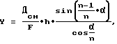
где α - угол поворота плоскопараллельной пластины относительно оптической оси канала наведения в плоскости линии визирования;
h - оптическая толщина пластины;
n - показатель преломления материала пластины;
Дсн - программная дальность снаряда;
F - эквивалентное фокусное расстояние оптической системы.When the plane-parallel plate deviates from the perpendicular optical axis of position, the information axis of the guidance beam shifts upward relative to the line of sight of the target by an amount that, in a simplified form, can be represented by the dependence:
where α is the angle of rotation of the plane-parallel plate relative to the optical axis of the guidance channel in the plane of the line of sight;
h is the optical thickness of the plate;
n is the refractive index of the plate material;
D sn - software range of the projectile;
F is the equivalent focal length of the optical system.
Закон изменения эквивалентного фокусного расстояния панкратической оптической системы 15 таков, что отношение фокусного расстояния F к текущей (программной) дальности снаряда Дсн сохраняется постоянным в течение всего полета ![]()
![]()
Описанный механизм поворота плоскопараллельной пластины при взаимодействии его с дальномерным каналом позволяет реализовать циклограмму работы прицела при наведении снаряда с введением и снятием превышения, представленную на фиг.2. The described mechanism of rotation of a plane-parallel plate when interacting with a rangefinder channel allows you to implement a cyclogram of the sight when aiming a projectile with the introduction and removal of excess, presented in figure 2.
Циклограммы на фиг.2 иллюстрируют работу механизмов прицела и величину превышения для одного варианта программы ввода и снятия превышения,
где τ0 - замер дальности;
τ1 - установка начального превышения;
τ2 - выстрел (СХОД);
τ3 - ввод максимального превышения;
τ4 - прерывание цикла наведения - принудительное снятие превышения (ВОЗВРАТ);
τ5 - начало снятия превышения;
τ6 - снятие превышения (вывод снаряда на линию прицеливания);
τ7 - поражение цели.The cyclograms in figure 2 illustrate the operation of the mechanisms of the sight and the magnitude of the excess for one version of the input and removal of excess
where τ 0 - range measurement;
τ 1 - setting the initial excess;
τ 2 - shot (SED);
τ 3 - input of the maximum excess;
τ 4 - interruption of the guidance cycle - forced removal of excess (RETURN);
τ 5 - the beginning of the removal of excess;
τ 6 - removal of excess (projectile output to the aiming line);
τ 7 - defeat of the target.
Датчик положения пластины может быть выполнен по любой из известных схем электрических, электромагнитных или оптронных концевых выключателей. В упрощенной системе датчик положения можно заменить датчиками начального и конечного положений. Поскольку привод механизма поворота предпочтительно реализуется на шаговом двигателе (например, ДШР46-0,0025-1,8), в качестве датчика положения может быть использована простейшая схема подсчета шагов двигателя. The plate position sensor can be made according to any of the known schemes of electrical, electromagnetic or optocoupler limit switches. In a simplified system, the position sensor can be replaced with start and end position sensors. Since the drive of the rotation mechanism is preferably implemented on a stepper motor (for example, ДШР46-0.0025-1.8), a simple scheme for calculating the steps of the motor can be used as a position sensor.
Описанное устройство введения превышения во взаимодействии с другими устройствами прицела позволяет решить задачу обеспечения помехозащищенности снарядов в процессе наведения. The described device for introducing excess in cooperation with other devices of the sight allows us to solve the problem of providing noise immunity of shells during the guidance process.
Панкратический объектив 28 представляет из себя оптическую систему с подвижными компонентами, за счет изменения положения которых происходит изменение его фокусного расстояния. В составе объектива имеется электродвигатель с механическим редуктором, преобразующим вращение вала двигателя в линейное перемещение подвижных элементов оптической схемы. Схема управления 29, датчик положения 30 и устройство возврата 31 панкратической системы 15 могут быть выполнены аналогичными соответствующим узлам устройства введения превышения 14. The pancratic lens 28 is an optical system with moving components, due to a change in the position of which there is a change in its focal length. The lens contains an electric motor with a mechanical gearbox that converts the rotation of the motor shaft into linear movement of the moving elements of the optical circuit. The control circuit 29, the position sensor 30 and the return device 31 of the pancratic system 15 can be made similar to the corresponding nodes of the introduction device of the excess 14.
Логическое устройство представляет собой в общем виде контроллер, содержащий устройство отсчета времени. Контроллер может быть выполнен на однокристальной микроЭВМ 1830ВЕ51, реализующей, например, структурную схему, приведенную на фиг.3. Контроллер позволяет реализовать достаточно большой набор программ управления как устройством введения превышения 14, так и панкратической оптической системой 15. Это позволяет менять соответствующие законы управления в зависимости не только от типа снаряда и дальности до цели, но и от других условий, например от метеорологических. Параметры таких условий для выбора соответствующих программ могут поступать на контроллер с центрального вычислителя комплекса. The logical device is a general form of the controller containing the device for counting time. The controller can be performed on a single-chip microcomputer 1830BE51, implementing, for example, the structural diagram shown in Fig.3. The controller allows you to implement a fairly large set of control programs as the device for the introduction of excess 14, and pankraticheskoy optical system 15. This allows you to change the appropriate control laws depending not only on the type of projectile and range to the target, but also on other conditions, such as meteorological. Parameters of such conditions for selecting the appropriate programs can be sent to the controller from the central computer of the complex.
Формирователь признака снаряда по типу баллистических характеристик 4 в простейшем случае представляет собой определенный набор перемычек в разъеме стыковки снаряда с ПУ. Код, сформированный таким образом, поступает по шине управления 16 на логическое устройство 10 и центральный вычислитель. Датчик положения оси ПУ 5 может быть выполнен на основе стандартных гироскопических датчиков угла, расположенных в двух взаимно перпендикулярных направлениях. Shaper of the sign of the projectile by the type of ballistic characteristics 4 in the simplest case is a certain set of jumpers in the connector of the docking of the projectile with PU. The code generated in this way is transmitted via the control bus 16 to the logic device 10 and the central computer. The axis
Описанные выше способ и устройство позволяют производить наведение различных типов снарядов с обеспечением их помехозащищенности, а также автоматизировать процесс запуска снарядов с различных ПУ и позволяют, таким образом, решить задачи предлагаемого изобретения. The method and device described above allow the guidance of various types of shells to ensure their noise immunity, as well as automate the process of launching shells from various launchers and, thus, solve the problems of the present invention.
Источники информации
1. Заявка РФ 97103054/02, МКИ 6 F 42 В 15/00, 28.02.97.Sources of information
1. Application of the Russian Federation 97103054/02, MKI 6 F 42 V 15/00, 02/28/97.
2. Патент США 5427328, НКИ 244-3.13, 12.02.85. 2. US patent 5427328, NKI 244-3.13, 12.02.85.
3. Патент США 4111383, НКИ 244-3.13, 05.09.78. 3. US patent 4111383, NKI 244-3.13, 09.09.78.
4. Патент ФРГ 4137843, МКИ F 41 G 1/38, 19.05.93. 4. Patent of Germany 4137843, MKI F 41
5. Патент РФ 2126946, МКИ 6 F 41 G 7/26, 25.11.97. 5. RF patent 2126946, MKI 6 F 41
6. Патент РФ 2126522, МКИ 6 F 41 G 7/26, 20.02.99. 6. RF patent 2126522, MKI 6 F 41
Claims (7)
Priority Applications (1)
| Application Number | Priority Date | Filing Date | Title |
|---|---|---|---|
| RU2001114907/02A RU2205347C2 (en) | 2001-05-30 | 2001-05-30 | Method for missile firing and missile guidance system |
Applications Claiming Priority (1)
| Application Number | Priority Date | Filing Date | Title |
|---|---|---|---|
| RU2001114907/02A RU2205347C2 (en) | 2001-05-30 | 2001-05-30 | Method for missile firing and missile guidance system |
Publications (2)
| Publication Number | Publication Date |
|---|---|
| RU2001114907A RU2001114907A (en) | 2003-02-10 |
| RU2205347C2 true RU2205347C2 (en) | 2003-05-27 |
Family
ID=20250273
Family Applications (1)
| Application Number | Title | Priority Date | Filing Date |
|---|---|---|---|
| RU2001114907/02A RU2205347C2 (en) | 2001-05-30 | 2001-05-30 | Method for missile firing and missile guidance system |
Country Status (1)
| Country | Link |
|---|---|
| RU (1) | RU2205347C2 (en) |
Cited By (2)
| Publication number | Priority date | Publication date | Assignee | Title |
|---|---|---|---|---|
| RU2516383C1 (en) * | 2012-11-29 | 2014-05-20 | Открытое акционерное общество "Конструкторское бюро приборостроения" | Method of launching laser beam-guided rocket |
| RU2564051C1 (en) * | 2014-06-25 | 2015-09-27 | Акционерное общество "Конструкторское бюро приборостроения им. академика А.Г. Шипунова" | Method of deflection shooting by anti-tank guided missile |
-
2001
- 2001-05-30 RU RU2001114907/02A patent/RU2205347C2/en active
Cited By (2)
| Publication number | Priority date | Publication date | Assignee | Title |
|---|---|---|---|---|
| RU2516383C1 (en) * | 2012-11-29 | 2014-05-20 | Открытое акционерное общество "Конструкторское бюро приборостроения" | Method of launching laser beam-guided rocket |
| RU2564051C1 (en) * | 2014-06-25 | 2015-09-27 | Акционерное общество "Конструкторское бюро приборостроения им. академика А.Г. Шипунова" | Method of deflection shooting by anti-tank guided missile |
Similar Documents
| Publication | Publication Date | Title |
|---|---|---|
| US9110295B2 (en) | System and method of controlling discharge of a firearm | |
| US4266463A (en) | Fire control device | |
| KR100337276B1 (en) | Impulse radar guidance apparatus and method for use with guided projectiles | |
| EP2577215B1 (en) | Optically-coupled communication interface for a laser-guided projectile | |
| RU2205347C2 (en) | Method for missile firing and missile guidance system | |
| ES475998A1 (en) | Fire control equipment. | |
| US20180231354A1 (en) | Method and apparatus for improving the aim of a weapon station, firing a point-detonating or an air-burst projectile | |
| RU2516383C1 (en) | Method of launching laser beam-guided rocket | |
| RU2219483C2 (en) | Method for firing by guided missile and missile guidance system | |
| US11933585B2 (en) | Method and apparatus for improving the aim of a weapon station, firing a point-detonating or an air-burst projectile | |
| RU2224206C1 (en) | Optical sight of fire control system (modifications) | |
| RU2183808C2 (en) | Optical sight of missile guidance system | |
| RU2212619C2 (en) | Optical sight of missile guidance system | |
| GB2068091A (en) | An optical aiming device | |
| RU2079090C1 (en) | Technique of sighting | |
| USH796H (en) | Open loop seeker aiming guiding system | |
| RU2001114907A (en) | CONTROLLED APPLIANCE SHOOTING METHOD AND CONTROLLED APPLIANCE GUIDING SYSTEM | |
| RU2100823C1 (en) | System for detection and recognition | |
| RU2126522C1 (en) | Guided missile guidance system | |
| RU2247299C1 (en) | Method for beam guidance of missiles and system for its realization | |
| RU1621676C (en) | Method of gun orientation and laying at fire from defilade and device for its accomplishment | |
| US3508335A (en) | Method of and device for establishing the correct lead required for firing a projectile at a moving target | |
| RU2077019C1 (en) | Sighting device | |
| RU66021U1 (en) | SYSTEM FOR CHANGING THE PARAMETERS OF LASER RADIATION OF A GUIDING CHANNEL | |
| RU2702458C1 (en) | Firing method guided by a laser beam |
Legal Events
| Date | Code | Title | Description |
|---|---|---|---|
| PC43 | Official registration of the transfer of the exclusive right without contract for inventions |
Effective date: 20150903 |