RU2204018C2 - Explosive device and method of blasting - Google Patents
Explosive device and method of blasting Download PDFInfo
- Publication number
- RU2204018C2 RU2204018C2 RU99106794/03A RU99106794A RU2204018C2 RU 2204018 C2 RU2204018 C2 RU 2204018C2 RU 99106794/03 A RU99106794/03 A RU 99106794/03A RU 99106794 A RU99106794 A RU 99106794A RU 2204018 C2 RU2204018 C2 RU 2204018C2
- Authority
- RU
- Russia
- Prior art keywords
- hole
- explosive
- air
- holes
- housing
- Prior art date
Links
Images

Classifications
-
- E—FIXED CONSTRUCTIONS
- E21—EARTH OR ROCK DRILLING; MINING
- E21C—MINING OR QUARRYING
- E21C37/00—Other methods or devices for dislodging with or without loading
- E21C37/06—Other methods or devices for dislodging with or without loading by making use of hydraulic or pneumatic pressure in a borehole
- E21C37/14—Other methods or devices for dislodging with or without loading by making use of hydraulic or pneumatic pressure in a borehole by compressed air; by gas blast; by gasifying liquids
Landscapes
- Engineering & Computer Science (AREA)
- Mining & Mineral Resources (AREA)
- Life Sciences & Earth Sciences (AREA)
- General Life Sciences & Earth Sciences (AREA)
- Geochemistry & Mineralogy (AREA)
- Geology (AREA)
- Drilling And Exploitation, And Mining Machines And Methods (AREA)
- Processing Of Meat And Fish (AREA)
- Eye Examination Apparatus (AREA)
- Surgical Instruments (AREA)
- Perforating, Stamping-Out Or Severing By Means Other Than Cutting (AREA)
- Earth Drilling (AREA)
- Filling Or Discharging Of Gas Storage Vessels (AREA)
Abstract
Description
Изобретение относится к взрывному устройству и способу взрывания для использования при взрывании горных пород, в частности на открытых горных разработках. The invention relates to an explosive device and method of blasting for use in blasting rocks, in particular in opencast mining.
В наиболее распространенных операциях при осуществлении взрывных работ в горных породах в качестве взрывчатого вещества используют нитроприлл. В настоящее время на открытых горных разработках взрывные работы проводят, во-первых, путем бурения шпуров в определенном порядке в пласте горной породы, подлежащем взрыванию. При открытых горных разработках взрывные работы производят на террасах, причем часть террасы, которую предполагают взорвать, известна под названием пласт. В каждый шпур затем закладывают взрывчатое вещество, после чего из непосредственной зоны взрывных работ должны быть удалены весь персонал и оборудование, которое может быть повреждено, перед началом взрывов. После проведения взрывов зона должна быть освобождена полностью от минерального сырья и пустой породы, которые могут повредить используемое на месте оборудование. В добавление к присущим в данных условиях опасностям эти обычные способы проведения взрывных работ имеют много других недостатков, включая высокую стоимость работ по заполнению шпуров, высокую стоимость поставки и транспортировки используемых взрывчатых веществ. Прекращение операций по добыче во время проведения взрывных работ и зачистка непосредственной зоны после проведения взрывов увеличивают стоимость и затраты времени при выполнении таких операций. In the most common operations during blasting in rocks, nitropril is used as explosive. Currently, in opencast mining, blasting is carried out, firstly, by drilling holes in a certain order in the rock formation to be blasted. In open pit mining, blasting is carried out on terraces, and part of the terrace, which is supposed to be blown up, is known as a layer. Explosive is then poured into each hole, after which all personnel and equipment that may be damaged must be removed from the immediate area of blasting before explosions begin. After the explosions, the area must be completely freed from minerals and waste rock, which can damage the equipment used on site. In addition to the hazards inherent in these conditions, these conventional blasting methods have many other drawbacks, including the high cost of filling holes, the high cost of supplying and transporting used explosives. The termination of mining operations during blasting operations and the cleaning of the immediate area after explosions increase the cost and time spent in performing such operations.
В патенте США 5116104 раскрыто взрывное устройство, подсоединяемое к источнику сжатого газа и вводимое в предварительно подготовленный шпур, содержащее одну или несколько пневматических пушек, размещенных в корпусе. Каждая пневматическая пушка снабжена сопряженным с ней отверстием в корпусе, через которое газ, вырывающийся из пневматической пушки, направляется под высоким давлением и с высокой скоростью для создания взрывного эффекта. Устройство имеет, по меньшей мере, один паккер, расположенный на одном конце устройства и способный образовывать уплотнение между корпусом и стенками окружающего шпура таким образом, что жидкость, подаваемая в шпур перед выполнением взрывной операции устройством, удерживается в шпуре. US 5,116,104 discloses an explosive device connected to a source of compressed gas and injected into a pre-prepared hole containing one or more air guns housed in a housing. Each air gun is equipped with an associated hole in the housing through which gas escaping from the air gun is directed at high pressure and at high speed to create an explosive effect. The device has at least one packer located at one end of the device and capable of forming a seal between the body and the walls of the surrounding borehole so that the fluid supplied to the borehole before the blasting operation is carried out by the device is held in the borehole.
Из указанного патента известен также способ взрывания согласно которому используют, по крайней мере, одно вышеописанное устройство, бурят шпур или группу шпуров в пласте, подлежащем взрыванию, упомянутое устройство вводят в шпур, подают жидкость в шпур вокруг устройства и производят выстреливание из пневматической пушки или пневматических пушек, высвобождая сжатый воздух, подаваемый от источника, из пневматической пушки или пневматических пушек и заставляя его проходить через отверстие или отверстия для создания взрывного эффекта, действующего на пласт, окружающий шпур. The blasting method is also known from the said patent, according to which at least one of the above devices is used, a hole is drilled or a group of holes in the formation to be blasted, the said device is introduced into the hole, liquid is supplied into the hole around the device and shot from an air gun or air gun guns, releasing compressed air supplied from a source from an air gun or air guns and causing it to pass through a hole or holes to create an explosive effect, de acting per formation surrounding the hole.
Техническим результатом настоящего изобретения является создание эффективных и экономичных взрывного устройства и способа взрывания. The technical result of the present invention is the creation of an effective and economical explosive device and method of blasting.
Указанный технический результат достигается тем, что взрывное устройство, подсоединяемое к источнику сжатого газа и вводимое в предварительно подготовленный шпур, содержит одну или несколько пневматических пушек, размещенных в корпусе, причем каждая пневматическая пушка снабжена сопряженным с ней отверстием в корпусе, через которое газ, вырывающийся из пневматической пушки, направляется под высоким давлением и с высокой скоростью для создания взрывного эффекта, по меньшей мере, один паккер, расположенный на одном конце устройства и способный образовывать уплотнение между корпусом и стенками окружающего шпура таким образом, что жидкость, подаваемая в шпур перед выполнением взрывной операции устройством, удерживается в шпуре. Согласно изобретению каждая пневматическая пушка содержит две камеры высокого давления, расположенные по обе стороны от выхлопной камеры, изолированной от камер высокого давления затвором, имеющим переключающий поршень и превышающий его по площади выстреливающий поршень, при этом устройство снабжено трубопроводом с системой управления для отвода сжатого газа из одной камеры высокого давления для обеспечения срывания с места переключающего поршня и перемещения затвора, позволяющего воздуху во взрывном режиме выйти из камер высокого давления в выхлопную камеру. The specified technical result is achieved in that the explosive device connected to a source of compressed gas and introduced into a pre-prepared hole contains one or more pneumatic guns located in the housing, each pneumatic gun equipped with an associated hole in the housing through which gas escaping from a pneumatic gun, sent at high pressure and at high speed to create an explosive effect, at least one packer located at one end of the device and special to form a seal between the housing and the walls of the surrounding borehole so that the fluid supplied to the borehole before the blasting operation of the device is held in the borehole. According to the invention, each air gun contains two high-pressure chambers located on both sides of the exhaust chamber, isolated from the high-pressure chambers by a shutter having a switching piston and a firing piston larger than it in area, and the device is equipped with a pipeline with a control system for removing compressed gas from one high-pressure chamber to ensure tearing from the place of the switching piston and move the shutter, allowing air to escape from the high-pressure chambers in explosive mode pressure into the exhaust chamber.
Возможно в качестве сжатого газа использовать воздух. It is possible to use air as compressed gas.
Предпочтительно, чтобы корпус имел трубчатую форму, содержащую множество отверстий или выхлопных ходов, расположенных вдоль одной его стороны. Резиноподобная обкладка может быть расположена в корпусе с отверстиями, соответствующими упомянутым отверстиям. Отверстия могут иметь овальную форму, хотя и другие формы могут быть найдены подходящими. Конкретно, было установлено, что Т-образная форма отверстия обладает определенными достоинствами, заключающимися в том, что они дают возможность снизить отдачу, воздействующую на пневматическую пушку, вызванную действием сжатого воздуха, которому предоставлена возможность выхода с достаточно высокой скоростью из выхлопной камеры пневматической пушки. Preferably, the housing has a tubular shape containing a plurality of holes or exhaust passages located along one side thereof. The rubber-like lining may be located in the housing with holes corresponding to said holes. The holes may have an oval shape, although other shapes may be found suitable. Specifically, it was found that the T-shape of the hole has certain advantages, namely, that it makes it possible to reduce the recoil affecting the air gun caused by the action of compressed air, which is allowed to exit the exhaust chamber of the air gun with a sufficiently high speed.
Предпочтительно паккеру придают форму надутого сальника. Preferably, the packer is shaped into an inflated seal.
Устройство может дополнительно содержать каскад для подачи жидкости в шпур. Лучше, если каскад расположен так, чтобы обеспечить условия, при которых жидкость, выходящая из каскада, смывает корпус в области отверстий для предотвращения скопления пустой породы из шпура, снижающее эффективность устройства. The device may further comprise a cascade for supplying fluid to the hole. It is better if the cascade is located so as to provide conditions under which the fluid leaving the cascade flushes the casing in the area of the openings to prevent the accumulation of gangue from the hole, which reduces the efficiency of the device.
Следует учесть, что паккер или паккеры можно располагать в любом месте на корпусе устройства, чтобы удовлетворить требованиям конкретной технологии взрывов. Например, если требуется взорвать горную породу в нижней части пласта, то паккер можно расположить около нижнего конца устройства, чтобы удерживать жидкость, которая в противном случае проникала бы в подрубаемую часть пласта. It should be noted that the packer or packers can be located anywhere on the device to meet the requirements of a specific explosion technology. For example, if you want to blow up rock in the lower part of the formation, the packer can be positioned near the lower end of the device to hold fluid that would otherwise penetrate into the undercut part of the formation.
Указанный результат достигается также в способе взрывания, при котором используют, по крайней мере, одно взрывное устройство, описанное выше, и при котором бурят шпур или группу шпуров в пласте, подлежащем взрыванию, упомянутое устройство вводят в шпур, подают жидкость в шпур вокруг устройства и производят выстреливание из пневматической пушки или пневматических пушек, высвобождая сжатый газ, подаваемый от источника, из пневматической пушки или пневматических пушек и заставляя его проходить через отверстие или отверстия в корпусе устройства для создания взрывного эффекта, действующего на пласт, окружающий шпур. The specified result is also achieved in the blasting method, in which at least one explosive device described above is used, and in which a hole or a group of holes are drilled in the formation to be blasted, said device is introduced into the hole, liquid is supplied into the hole around the device and firing from an air gun or air guns, releasing the compressed gas supplied from the source, from an air gun or air guns and forcing it to pass through a hole or holes in the housing ARISING to create an explosive effect, acting on the formation surrounding the hole.
Для более четкого понимания изобретения приведен ряд вариантов исполнения изобретения, которые далее будут описаны ниже со ссылками на прилагаемые чертежи, на которых изображено следующее:
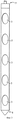
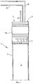
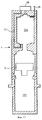
фиг.1 изображает продольное сечение взрывного устройства, выполненного в соответствии с настоящим изобретением;
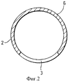
фиг.2 - поперечное сечение взрывного устройства по линии А-А на фиг.1;
фиг.3 - вид передней стороны, показанного на фиг.1 устройства, ниже которой расположены отверстия;
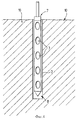
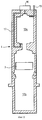
фиг. 4 - вид взрывного устройства, показанного на фиг.1, расположенного на месте, подготовленного для проведения взрыва;
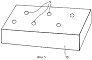
фиг. 5 - вид в перспективе типичной группы шпуров, используемой для взрывания пласта;
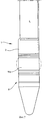
фиг. 6 - вид сбоку верхней части устройства, выполненного в соответствии со следующим вариантом исполнения настоящего изобретения;
фиг.7 - аналогичный вид нижней части устройства, представленного на фиг. 6;
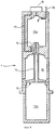
фиг. 8 - подробный боковой вид поперечного сечения, на котором показано отверстие и пневматическая пушка устройства, представленного на фиг.6, за исключением затвора для упрощения изображения;
фиг. 9 - аналогичный вид, на котором показана пневматическая пушка в заряженном состоянии с затвором;
фиг. 10 - аналогичный вид, на котором показана пневматическая пушка в мгновенном положении максимального смещения затвора после осуществления выстрела;
фиг.11 - вид, аналогичный изображенному на фиг.8, на котором показан вариант исполнения отверстия.For a clearer understanding of the invention, a number of embodiments of the invention are given, which will be described below with reference to the accompanying drawings, which show the following:
figure 1 depicts a longitudinal section of an explosive device made in accordance with the present invention;
figure 2 is a cross section of an explosive device along the line aa in figure 1;
figure 3 is a view of the front side shown in figure 1 of the device, below which the holes are located;
FIG. 4 is a view of the explosive device shown in figure 1, located in place, prepared for the explosion;
FIG. 5 is a perspective view of a typical group of holes used for blasting a formation;
FIG. 6 is a side view of the upper part of a device made in accordance with the following embodiment of the present invention;
7 is a similar view of the lower part of the device shown in FIG. 6;
FIG. 8 is a detailed lateral cross-sectional view showing the hole and air gun of the device of FIG. 6, except for a shutter to simplify the image;
FIG. 9 is a similar view showing the air gun in a charged state with a shutter;
FIG. 10 is a similar view showing the air gun in the instantaneous position of maximum shutter displacement after firing;
11 is a view similar to that shown in Fig. 8, which shows an embodiment of the hole.
Взрывное устройство 1 (фиг.1-5) содержит корпус, в данном случае изготовленный из бесшовной термически обработанной трубы 2 (Британский стандарт DIN 2448/1629 ST52 или эквивалентный ему) с толщиной стенки, приблизительно равной 20 мм, длиной около 9 м и диаметром 150-200 мм. В трубе 2 имеются овальные отверстия 3, расположенные с одинаковым шагом вдоль передней стороны, причем отверстия 3 имеют максимальную высоту приблизительно 900 мм и максимальную ширину приблизительно 150 мм. Отдельные пушки 4, в качестве которых могут быть использованы сейсмические пушки обычной конструкции, расположены около каждого отверстия 3 в трубе, причем каждая пушка 4 имеет длину приблизительно 900 мм. Сверху и снизу от каждой пушки 4 приварена круглая плита 5 толщиной приблизительно 20 мм, для перегораживания трубы 2. Эти плиты 5 также способствуют приданию жесткости трубе 2 и могут служить опорами для пушек 4. Между плитами 5 с каждой стороны пушки 4 находится мертвое пространство, составляющее приблизительно 900 мм трубы 2, и с верхнего конца 7 и нижнего конца 8 устройства 1 находятся мертвые пространства в трубе 2, составляющие приблизительно 500 мм. An explosive device 1 (Figs. 1-5) comprises a body, in this case made of seamless heat-treated pipe 2 (British Standard DIN 2448/1629 ST52 or equivalent) with a wall thickness of approximately 20 mm, a length of about 9 m and a diameter 150-200 mm. In the
Нижний конец 8 трубы 2 под самой нижней пушкой 4 выполнен в форме конуса для облегчения введения устройства 1 в пробуренный шпур. Сжатый воздух к пушкам 4 подают от источника сжатого воздуха, предпочтительно компрессора (не показан), который подсоединяют с помощью соответствующего трубопровода к коллектору, по которому подают сжатый воздух к пневматическим пушкам. The
Пневматические пушки 4 заряжают перед выстрелом сжатым воздухом от компрессора, причем поддерживают давление сжатого воздуха с помощью клапана в каждой пушке до тех пор, пока все клапаны одновременно не переключают в открытое положение. При выстреле пневматических пушек 4 они создают удар воздуха из каждой пушки, направленный наружу из отверстия 3, в виде толчка давления. Плиты 5 способствуют фокусированию толчка давления, создаваемого сжатым воздухом, выходящим из отверстий 3.
Пневмопровод направлен от компрессора для создания требуемого давления сжатого воздуха, например 180 бар, и его вводят в устройство с помощью трубопроводной арматуры так, чтобы подать в герметичное пространство у верхнего конца трубы 2. Пневмопровод затем вводят под внутреннюю поверхность трубы 2 со стороны, противоположной отверстиям 3, пропускают через малые уплотненные отверстия в каждой плите 5 так, чтобы распределять сжатый воздух по коллектору (не показан) к каждой пушке 4. The air line is directed from the compressor to create the required pressure of compressed air, for example 180 bar, and it is introduced into the device using pipe fittings so as to be fed into the sealed space at the upper end of the
Специалистам в данной области техники должно быть понятно, что устройство, описанное выше, пригодно для взрыва пласта горной породы толщиной 9 м. Однако устройство может быть использовано для взрывания пласта почти любой толщины простым изменением длины, ширины и количества применяемых пушек и может быть использовано в шпурах любого большего диаметра, практикуемого в настоящее время. Изменяя форму отверстий 3 и/или шаг между пушками 4, можно создавать различные взрывные эффекты, и шаг между пушками 4 не обязательно должен быть регулярным. Specialists in the art should understand that the device described above is suitable for blasting a rock formation with a thickness of 9 m. However, the device can be used to blast a formation of almost any thickness by simply changing the length, width and number of guns used and can be used in holes of any larger diameter currently practiced. By changing the shape of the
Кроме того, путем использования соответствующей конструкции пневмопровода выстреливание пушек 4 может быть произведено не только одновременно, но и в виде очередей или в определенном порядке. In addition, by using the appropriate design of the pneumatic line, the firing of the
Устройство, в одном конкретном варианте исполнения (не показано), подсоединяют к обычной буровой установке только с небольшой модификацией, требующейся для присоединения устройства к установке, например в форме кронштейна. Буровая установка должна содержать компрессор, который обеспечивает давление сжатого воздуха, требуемое для выстреливания пневматических пушек. В случае взрывания пласта толщиной 9 м оснащение требует опорной рамы величиной 9 м, с которой можно вводить устройство в пробуренные шпуры. The device, in one particular embodiment (not shown), is connected to a conventional drilling rig with only the slight modification required to connect the device to the rig, for example in the form of a bracket. The rig should include a compressor that provides the compressed air pressure required to fire the air guns. In the event of a blasting of a 9 m thick formation, the equipment requires a 9 m support frame from which the device can be inserted into drilled holes.
В другом непоказанном варианте исполнения устройство присоединяют к установке посредством каретки на опорной раме. Лебедка, присоединенная посредством троса к рым-болту наверху устройства, позволяет опускать устройство в пробуренный шпур и спускать с опорной рамы так, чтобы обеспечить возможность убирать буровую установку с места взрыва, оставляя устройство подсоединенным к установке с помощью троса лебедки и пневмолинии. Пушки выстреливают при переключении триггера на установке и, таким образом, выстрел производят с безопасного расстояния. После завершения взрыва установка может быть возвращена на место и устройство может быть поднято с места взрыва с использованием лебедки и каретки на опорной раме. Буровая установка может дополнительно нести устройство и для простоты бур может работать от того же компрессора, что и устройство. Это позволяет использовать одну установку для проведения взрывных работ на "пласте" от бурения шпуров до выстреливания из пушек. Путем использования бура и взрывного устройства, объединенных в одну установку, можно производить выстреливание из пушек после бурения шпуров, расположенных один рядом с другим. In another embodiment not shown, the device is connected to the installation by means of a carriage on a support frame. A winch connected via a cable to an eyebolt at the top of the device allows you to lower the device into the drilled hole and lower it from the support frame so that it is possible to remove the drilling rig from the site of the explosion, leaving the device connected to the installation using a winch cable and a pneumatic line. The guns are fired when the trigger is switched on the installation and, thus, the shot is fired from a safe distance. After the explosion is completed, the installation can be returned to the place and the device can be lifted from the place of the explosion using a winch and a carriage on the support frame. The drilling rig may further carry the device and, for simplicity, the drill may operate from the same compressor as the device. This allows you to use one installation for blasting on the "bed" from drilling holes to firing from guns. By using a drill and an explosive device, combined into one installation, it is possible to fire from guns after drilling holes located next to each other.
Устройство должно быть расположено в шпуре 9 (фиг.4) так, чтобы передняя сторона устройства была обращена к участку пласта 10, который предполагают взорвать. Толчки давления при выстреливании пушек 4 направлены из отверстий 3 с передней стороны устройства. The device should be located in the hole 9 (figure 4) so that the front side of the device is facing the section of the
Рисунок расположения шпуров 9, показанный на фиг.5, аналогичен рисунку расположения шпуров, применяемому при выполнении обычных операций в горных разработках. Однако эта группа шпуров также обеспечивает наиболее эффективные результаты при использовании устройства, выполненного в соответствии с настоящим изобретением. The
На фиг.6-11, на которых соответствующие элементы обозначены теми же позициями, которые были использованы в ранее приведенном описании, показан следующий вариант исполнения взрывного устройства 1. Устройство 1 содержит корпус, в данном случае цилиндрическую металлическую трубу 2, в котором размещена группа пневматических пушек 4, как показано более подробно на фиг. 3-5. Каждая пневматическая пушка 4 расположена у отверстия 3 в трубе 2, причем отверстия 3 расположены в одной и той же плоскости. Сжатый воздух подают к каждой пневматической пушке 4 по коллектору 19 в корпусе, причем имеется электрическая или какая-либо другая система управления выстреливанием, включающая кабель 20, например оптико-волоконный кабель. Точка 9 присоединения трубопровода для подачи воды размещена на верхнем конце 7 корпуса устройства, от которой воду подают в каскад 10, размещенный у верхнего конца 7 корпуса устройства и, следовательно, выше отверстий 3. Корпус далее снабжен верхним и нижним накаченными сальниками или паккерами 11, 11b, расположенными соответственно около концов 7, 8 корпуса. Обычно паккеры 11а, 11b накачивают, используя ту же систему подачи сжатого воздуха, от которой питают пневматические пушки 4. 6-11, in which the corresponding elements are denoted by the same positions that were used in the previous description, the following embodiment of the
Устройство действует следующим образом. The device operates as follows.
Устройство 1 вводят в предварительно подготовленный шпур (не показан), подвешенное на тросе 21, причем паккеры 11, 11b не надуты. Когда устройство установлено в шпуре, паккеры 11а, 11b надувают и подают воду в шпур по каскаду 10. Следует отметить, что вода, поступающая из каскада 10, проходит вниз по трубе 2, образующей корпус, и способствует удалению породы из зоны расположения отверстий 3. Воду подают до тех пор, пока шпур и полости в корпусе за отверстиями, образованными каждой выхлопной камерой 18 пневматической пушки 4, не заполнятся. Затем устройство может быть включено в действие путем выстреливания из пневматических пушек 4. The
Такие пневматические пушки 4 имеют обычный принцип действия, заключающийся в том, что сжатый воздух поступает и накапливается в камерах 12а, 12b высокого давления по обе стороны от выхлопной камеры 18. Затвор 13 изолирует выхлопную камеру 18 от камер 12а, 12b высокого давления в "заряженном" состоянии. Сжатый воздух выпускают во взрывном режиме из камер 12а, 12b высокого давления путем срывания с места переключающего поршня 14, расположенного на одном конце затвора 13, по трубопроводу 17 для отвода сжатого воздуха под контролем электромагнитного клапана 16. Путем срывания с места переключающего поршня 14 под давлением сжатого воздуха, действующего на выстреливающий поршень 15 большей площади, затвор 13 перемещается вверх против силы тяжести из его "заряженного" положения или положения в седле, позволяя воздуху выйти во взрывном режиме и перейти в выхлопную камеру 18, содержащую воду и расположенную позади одного отверстия или прохода 3. В результате воздушный пузырь расширяется и затем мгновенно распадается так, что кавитационный эффект разрушает структуру горной породы в зоне действия устройства рядом с отверстиями 3. В случае использования подземного варианта исполнения устройства следует применять выпускной клапан, обеспечивающий возможность выхода перемещаемого воздуха из пробуренного шпура при действии устройства в горизонтальном положении. Such
На фиг. 11 показан вариант исполнения отверстия, описанного выше, в котором отверстие 3 имеет Т-образную форму. Такая форма отверстия позволяет контролировать поток воздуха, вырывающийся из выхлопной камеры 18 пневматической пушки, так, чтобы выстреливающий поршень 15 не испытывал торможения из-за невозможности для воздуха покинуть выхлопную камеру достаточно быстро. In FIG. 11 shows an embodiment of the hole described above, in which the
Следует иметь ввиду специалистам в данной области техники, что описанный выше вариант исполнения может быть еще более усовершенствован в направлении повышения эффективности и облегчения использования описанного выше устройства. В отношении последнего пункта, в частности, паккеры могут быть надуты автоматически при контакте с водой. Такая особенность более удобна для верхнего паккера, который может служить для оператора индикатором того, что шпур заполнен водой. Кроме того, для предотвращения попадания жидкости в полость между пневматическими пушками это пространство может быть заполнено соответствующим пеноматериалом. It should be borne in mind by those skilled in the art that the embodiment described above can be further improved in the direction of increasing efficiency and facilitating the use of the device described above. In relation to the last point, in particular, packers can be inflated automatically in contact with water. This feature is more convenient for the top packer, which can serve as an indicator for the operator that the hole is filled with water. In addition, to prevent liquid from entering the cavity between the pneumatic guns, this space can be filled with appropriate foam.
К числу преимуществ устройства, выполненного в соответствии с настоящим изобретением, относится то, что его можно использовать повторно, в то время как взрывчатые вещества повторно использовать нельзя; устройство согласно изобретению не создает никаких взлетающих в воздух частиц породы; не требуется средств для доставки взрывчатых веществ и команд для их обслуживания; не требуются операции по очистке территории; может требоваться только один оператор; могут быть сокращены затраты времени; исключается риск головных болей из-за контакта с нитроглицерином; сейсмические пушки не создают загрязнений окружающей среды; много буровых установок, которые сейчас эксплуатируют, могут быть приспособлены для взаимодействия с одним из предложенных устройств. Отсутствие взрывных зарядов также способствует значительному снижению уровня шума, и при эффективно выполненной конструкции устройства, согласно изобретению, оно может действовать почти бесшумно. Among the advantages of the device made in accordance with the present invention, is that it can be reused, while explosives cannot be reused; the device according to the invention does not create any rock particles flying up into the air; no funds are required for the delivery of explosives and commands for their maintenance; cleaning operations are not required; only one operator may be required; time can be reduced; eliminates the risk of headaches due to contact with nitroglycerin; seismic guns do not create environmental pollution; many drilling rigs that are currently in operation can be adapted to interact with one of the proposed devices. The absence of explosive charges also contributes to a significant reduction in noise level, and with an efficiently designed device according to the invention, it can operate almost silently.
Следует также иметь ввиду, что различные изменения и модификации могут быть внесены в описанные выше варианты исполнения без отступления от объема изобретения. Примером модификации описанного выше варианта исполнения устройства может быть изготовление дополнительного отверстия или ряда отверстий на противоположной стороне трубы 2, т.е. обращенных на противоположную сторону относительно существующим отверстиям 3. Это может привести к сбалансированному взрыву и может, таким образом, снизить отдачу устройства 1. Это, в свою очередь, может быть эффективным с точки зрения срока службы устройства. It should also be borne in mind that various changes and modifications can be made to the above described embodiments without departing from the scope of the invention. An example of a modification of the above described embodiment of the device can be the manufacture of an additional hole or a series of holes on the opposite side of the
Устройство также может быть использовано в других областях применения, включая другие виды взрывов. Например, устройство может быть использовано в работах по сносу сооружений. Более того, там где требуется взорвать материал, имеющий большую толщину, два или более таких устройств может быть введено вместе в один шпур и, в этом случае, для удобства установка может нести более одного устройства. В определенных случаях применения, например, при гашении пожаров на газовых или нефтяных скважинах, вместо использования сжатого воздуха, устройство может быть "заряжено" инертным газом или газами, которые при высвобождении во взрывном режиме при выстреливании пневматической пушки или пневматических пушек подавляют и гасят пламя. The device can also be used in other applications, including other types of explosions. For example, the device can be used in demolition works. Moreover, where it is required to blow up material having a large thickness, two or more of these devices can be inserted together into one hole and, in this case, for convenience, the installation can carry more than one device. In certain applications, for example, when extinguishing fires in gas or oil wells, instead of using compressed air, the device can be “charged” with inert gas or gases that suppress and extinguish the flame when released in an explosive mode when firing an air gun or air guns.
Следует дополнительно отметить, что при выполнении обычных горнодобывающих операций сначала бурят все шпуры, затем вставляют взрывные заряды и взрывают их одновременно. При использовании настоящего изобретения может быть более эффективным пробурить шпур, затем произвести взрыв предложенным устройством, до того как бурить следующие шпуры в этом пласте. Это может способствовать предотвращению при взрыве в одном шпуре частичного разрушения другого, уже пробуренного шпура, и таким образом к созданию препятствий для введения в него устройства. It should be additionally noted that when performing ordinary mining operations, all bore holes are first drilled, then explosive charges are inserted and they are blown up simultaneously. Using the present invention, it may be more efficient to drill a hole, then explode with the proposed device, before drilling the next holes in this formation. This can help prevent, in an explosion in one hole, the partial destruction of another, already drilled hole, and thus create obstacles for introducing a device into it.
Claims (10)
30.04.1997 по пп. 1, 8, 9;
06.09.1996 по пп. 2-6, 10;
04.09.1997 по п. 7.Priorities for items:
04/30/1997 PP 1, 8, 9;
09/06/1996 PP 2-6, 10;
September 4, 1997 under item 7.
Applications Claiming Priority (4)
| Application Number | Priority Date | Filing Date | Title |
|---|---|---|---|
| GBGB9618596.2A GB9618596D0 (en) | 1996-09-06 | 1996-09-06 | Blasting device |
| GB9618596.2 | 1996-09-06 | ||
| GBGB9708864.5A GB9708864D0 (en) | 1997-04-30 | 1997-04-30 | Blasting device |
| GB9708864.5 | 1997-04-30 |
Publications (2)
| Publication Number | Publication Date |
|---|---|
| RU99106794A RU99106794A (en) | 2001-01-27 |
| RU2204018C2 true RU2204018C2 (en) | 2003-05-10 |
Family
ID=26309983
Family Applications (1)
| Application Number | Title | Priority Date | Filing Date |
|---|---|---|---|
| RU99106794/03A RU2204018C2 (en) | 1996-09-06 | 1997-09-04 | Explosive device and method of blasting |
Country Status (11)
| Country | Link |
|---|---|
| US (1) | US6305752B1 (en) |
| EP (1) | EP0927297B1 (en) |
| CN (1) | CN1114752C (en) |
| AT (1) | ATE201744T1 (en) |
| AU (1) | AU729961B2 (en) |
| BR (1) | BR9711393A (en) |
| CA (1) | CA2264812C (en) |
| DE (1) | DE69705056D1 (en) |
| PT (1) | PT927297E (en) |
| RU (1) | RU2204018C2 (en) |
| WO (1) | WO1998010169A1 (en) |
Families Citing this family (4)
| Publication number | Priority date | Publication date | Assignee | Title |
|---|---|---|---|---|
| GB0229986D0 (en) * | 2002-12-24 | 2003-01-29 | Flute Developments Ltd | Treatment of materials |
| CN104594866A (en) * | 2014-10-31 | 2015-05-06 | 河南神华能源工程有限公司 | New method for rapid gas drainage technology based on low permeability coal bed gas phase fracturing |
| CN105781549B (en) * | 2016-04-25 | 2019-03-12 | 重庆科技学院 | Device and method for combined blasting of rock with external air pressure and internal water bladder |
| CN114837674A (en) * | 2022-05-19 | 2022-08-02 | 四川芙蓉川南建设工程有限公司 | High-energy air blasting impact device and method |
Citations (1)
| Publication number | Priority date | Publication date | Assignee | Title |
|---|---|---|---|---|
| US5116104A (en) * | 1989-06-19 | 1992-05-26 | Mecseki Szenbanyak | Method and equipment for loosening and/or winning minerals especially coal and aggregated materials by using compressed air breaking |
Family Cites Families (10)
| Publication number | Priority date | Publication date | Assignee | Title |
|---|---|---|---|---|
| BE564144A (en) * | ||||
| US3018731A (en) * | 1951-11-17 | 1962-01-30 | Olin Mathieson | Shear member for gas operated blasting cartridge |
| US2636437A (en) * | 1952-02-29 | 1953-04-28 | Du Pont | Closure assembly for the discharge end of blasting devices |
| FR1257666A (en) * | 1960-01-30 | 1961-04-07 | Charbonnages De France | Improvements to blow molding devices |
| DE1298483B (en) * | 1967-05-08 | 1969-07-03 | Glueckauf Guenther Klerner Mas | Detonation pipe for devices for blasting off and dividing hard, compactly stored minerals with the help of highly compressed air |
| DE1299267B (en) * | 1967-05-08 | 1969-07-17 | Glueckauf Guenther Klerner Mas | Detonation pipe for devices for blasting off and dividing hard, compactly stored minerals with the help of compressed air |
| US4301731A (en) * | 1979-09-12 | 1981-11-24 | Zeto Industries, Inc. | Air shooting system for the mining of coal or the like |
| HU186827B (en) * | 1982-08-04 | 1985-09-30 | Mecseki Szenbanyak | Method and apparatus for hoeing and/or breaking coal beds, furthermoe other rock, lumpy or granular medium agglomerated into bed |
| DE3610149C2 (en) * | 1986-03-26 | 1994-09-15 | Wilhelm Leppak | Loading system and method for introducing a charging column consisting of several explosive cartridges into a borehole by means of the charging system |
| GB9216355D0 (en) * | 1992-07-31 | 1992-09-16 | Webb George H | An improved method of restraining a rock-breaking tube |
-
1997
- 1997-09-04 WO PCT/GB1997/002363 patent/WO1998010169A1/en not_active Ceased
- 1997-09-04 CA CA002264812A patent/CA2264812C/en not_active Expired - Fee Related
- 1997-09-04 AT AT97939018T patent/ATE201744T1/en not_active IP Right Cessation
- 1997-09-04 US US09/254,508 patent/US6305752B1/en not_active Expired - Fee Related
- 1997-09-04 CN CN97197707.0A patent/CN1114752C/en not_active Expired - Fee Related
- 1997-09-04 AU AU41250/97A patent/AU729961B2/en not_active Ceased
- 1997-09-04 PT PT97939018T patent/PT927297E/en unknown
- 1997-09-04 BR BR9711393-0A patent/BR9711393A/en not_active IP Right Cessation
- 1997-09-04 DE DE69705056T patent/DE69705056D1/en not_active Expired - Lifetime
- 1997-09-04 EP EP97939018A patent/EP0927297B1/en not_active Expired - Lifetime
- 1997-09-04 RU RU99106794/03A patent/RU2204018C2/en not_active IP Right Cessation
Patent Citations (1)
| Publication number | Priority date | Publication date | Assignee | Title |
|---|---|---|---|---|
| US5116104A (en) * | 1989-06-19 | 1992-05-26 | Mecseki Szenbanyak | Method and equipment for loosening and/or winning minerals especially coal and aggregated materials by using compressed air breaking |
Also Published As
| Publication number | Publication date |
|---|---|
| CN1229453A (en) | 1999-09-22 |
| EP0927297A1 (en) | 1999-07-07 |
| CA2264812A1 (en) | 1998-03-12 |
| PT927297E (en) | 2002-01-30 |
| US6305752B1 (en) | 2001-10-23 |
| AU729961B2 (en) | 2001-02-15 |
| DE69705056D1 (en) | 2001-07-05 |
| ATE201744T1 (en) | 2001-06-15 |
| CN1114752C (en) | 2003-07-16 |
| BR9711393A (en) | 2000-01-18 |
| CA2264812C (en) | 2007-01-02 |
| AU4125097A (en) | 1998-03-26 |
| WO1998010169A1 (en) | 1998-03-12 |
| EP0927297B1 (en) | 2001-05-30 |
Similar Documents
| Publication | Publication Date | Title |
|---|---|---|
| RU2081313C1 (en) | Method and device for crushing hard rock and materials | |
| US6499406B2 (en) | Blasting apparatus for forming horizontal underground cavities and blasting method using the same | |
| AP1053A (en) | Method for controlled fragmentation of hard rock and concrete by the combination use of impact hammers and small charge blasting. | |
| CN101198763B (en) | Drill | |
| US3623771A (en) | Drill-and-blast excavating apparatus and method | |
| US5611605A (en) | Method apparatus and cartridge for non-explosive rock fragmentation | |
| US3863723A (en) | Hole drill and debris clearance method and means | |
| RU2204018C2 (en) | Explosive device and method of blasting | |
| RU2164001C1 (en) | Self-propelled mount for cover of blast place | |
| CN110030001A (en) | A kind of construction method that mountain tunnel is appeared | |
| RU2053369C1 (en) | Method for weakening of coal massif | |
| RU2164293C2 (en) | Process of working of coal seams | |
| NO763071L (en) | PROCEDURE AND DEVICE FOR BREAKING A SOLID MATERIAL, SUCH AS A MOUNTAIN. | |
| RU2110764C1 (en) | Method of blastings by burn cut | |
| RU2186979C2 (en) | Method of mining of thick ore deposits | |
| RU2089844C1 (en) | Method of blasting of low-stable ore bodies | |
| KR200237333Y1 (en) | Blasting Apparatus for Forming a Horizontal Underground Cavity | |
| KR100400127B1 (en) | Blasting Apparatus for Forming a Horizontal Underground Cavity | |
| AU707387B2 (en) | Method, apparatus and cartridge for non-explosive rock fragmentation | |
| RU2236598C1 (en) | Method for protection from air-blast by temporary rock wall | |
| KR100400128B1 (en) | Method for Forming a Horizontal Underground Cavity using a Blasting Apparatus | |
| SU1745967A1 (en) | Coal and gas blowout prevention device for drilling holes and blastholes on outburst-hazardous seams | |
| RU2276723C2 (en) | Gas-hydroimpulsive device | |
| CN115788346A (en) | Drilling blowout prevention and gas extraction integrated hole sealing device and method | |
| RU2053361C1 (en) | Method for rock blasting |
Legal Events
| Date | Code | Title | Description |
|---|---|---|---|
| MM4A | The patent is invalid due to non-payment of fees |
Effective date: 20090905 |