RU2200103C2 - Device to increase locomotive wheels-to-rails adhesion - Google Patents
Device to increase locomotive wheels-to-rails adhesion Download PDFInfo
- Publication number
- RU2200103C2 RU2200103C2 RU2001102093A RU2001102093A RU2200103C2 RU 2200103 C2 RU2200103 C2 RU 2200103C2 RU 2001102093 A RU2001102093 A RU 2001102093A RU 2001102093 A RU2001102093 A RU 2001102093A RU 2200103 C2 RU2200103 C2 RU 2200103C2
- Authority
- RU
- Russia
- Prior art keywords
- rails
- locomotive
- magnetizing coil
- magnetic circuit
- power supply
- Prior art date
Links
- 230000003137 locomotive effect Effects 0.000 title claims abstract description 31
- 241001669679 Eleotris Species 0.000 claims 3
- 230000000694 effects Effects 0.000 abstract description 2
- 239000000126 substance Substances 0.000 abstract 1
- 230000004907 flux Effects 0.000 description 3
- 238000005096 rolling process Methods 0.000 description 2
- 230000005611 electricity Effects 0.000 description 1
- 239000012634 fragment Substances 0.000 description 1
- 230000006872 improvement Effects 0.000 description 1
- 230000005415 magnetization Effects 0.000 description 1
- 239000000463 material Substances 0.000 description 1
- 238000000034 method Methods 0.000 description 1
- 238000012986 modification Methods 0.000 description 1
- 230000004048 modification Effects 0.000 description 1
- 230000008569 process Effects 0.000 description 1
- 238000005245 sintering Methods 0.000 description 1
- 230000003068 static effect Effects 0.000 description 1
- 238000004804 winding Methods 0.000 description 1
Images
Landscapes
- Train Traffic Observation, Control, And Security (AREA)
Abstract
Description
Изобретение относится к железнодорожному транспорту, в частности к устройствам, предназначенным для увеличения тяги локомотива за счет увеличения сцепления колес с рельсами без увеличения нагрузки от оси на рельсы. The invention relates to railway transport, in particular to devices designed to increase traction of a locomotive by increasing the adhesion of wheels to rails without increasing the axle load on the rails.
Все известные устройства такого типа используют установленные на локомотивах электромагниты, полюсами которых являются колеса локомотивов, которые притягиваются за счет магнитных сил к рельсам, увеличивая сцепление последних с колесами. All known devices of this type use electromagnets mounted on locomotives, the poles of which are the wheels of locomotives, which are attracted due to magnetic forces to the rails, increasing the adhesion of the latter to the wheels.
Ближайшим прототипом для настоящего изобретения является устройство, в котором на оси колесной пары электровоза расположена намагничивающая обмотка, выполненная на каркасе, закрепленном на тележке электровоза, причем каркас расположен с зазорам соосно с осью колесной пары и на нем установлены подшипники качения, размещенные по торцам каркаса катушки с возможностью вращения оси колесной пары внутри него, что позволяет повысить сцепление колес электровоза с рельсами [1]. В этом устройстве сердечником электромагнита служит ось колесной пары, а полюсами сердечника, к которым притягиваются рельсы, являются колеса этой пары. Такое устройство имеет ряд существенных недостатков. Одним из них является разомкнутость магнитопровода (ось колесной пары - колеса - рельсы), который участвует в достижении полезного эффекта, а другим - объективное наличия магнитного шунта, обусловленное конструкцией электровоза, в результате чего часть магнитного поля катушки замыкается через этот шунт, который представляет собой замкнутый магнитопровод, состоящий из конструкций тележки и букс, что, в конечном итоге, уменьшает силы магнитного притяжения колес и рельсов. К другому недостатку относится необходимость значительной доработки электровоза для размещения на нем устройства. The closest prototype for the present invention is a device in which on the axis of the wheelset of the electric locomotive there is a magnetizing winding made on a frame mounted on a trolley of an electric locomotive, the frame being located with gaps coaxially with the axis of the wheel pair and rolling bearings are installed on it located at the ends of the coil frame with the possibility of rotation of the axis of the wheelset inside it, which allows to increase the adhesion of the wheels of an electric locomotive with rails [1]. In this device, the core of the electromagnet is the axis of the wheel pair, and the poles of the core to which the rails are attracted are the wheels of this pair. Such a device has a number of significant disadvantages. One of them is the open circuit of the magnetic circuit (the axis of the wheelset — wheel — rails), which is involved in achieving a useful effect, and the other is the objective presence of a magnetic shunt due to the design of the electric locomotive, as a result of which part of the magnetic field of the coil is closed through this shunt, which is closed magnetic circuit, consisting of the structures of the trolley and axle boxes, which, ultimately, reduces the magnetic forces of attraction of the wheels and rails. Another disadvantage is the need for significant improvement of the electric locomotive to place the device on it.
Целью изобретения является улучшение тяговых характеристик локомотива путем повышения сцепления колес с рельсами без увеличения нагрузки от оси на рельсы за счет направления прохождения всего магнитного потока катушки через место контакта колес с рельсами. The aim of the invention is to improve the traction characteristics of the locomotive by increasing the adhesion of the wheels to the rails without increasing the axle load on the rails due to the direction of passage of the entire magnetic flux of the coil through the point of contact of the wheels with the rails.
Указанная цель достигается тем, что рельсошпальная решетка, на которой установлено устройство, соединена с соседними рельсошпальными решетками немагнитными накладками, намагничивающая катушка устройства намотана на каркас, внутри которого находится средняя часть П-образного магнитопровода, расстояние между боковыми частями которого равно расстоянию между рельсами и которая располагается между шпалами параллельно им, причем боковые части магнитопровода своими полюсами подсоединены через электроизолирующие прокладки к рельсам, обеспечивая в месте соединения магнитный контакт, а блок электропитания, к выходу которого подключены выводы намагничивающей катушки, подключается к электропитающей сети через блок автоматической регистрации нахождения локомотива на рельсах рельсошпальной решетки, оборудованной устройством, генерируя в намагничивающей катушке электрический ток в течение времени, необходимого локомотиву для проезда по рельсам этой решетки. This goal is achieved by the fact that the rail-sleeper grid on which the device is installed is connected to adjacent rail-sleeper grids by non-magnetic overlays, the magnetizing coil of the device is wound on a frame, inside of which is the middle part of the U-shaped magnetic circuit, the distance between the side parts of which is equal to the distance between the rails and which is located between the sleepers parallel to them, and the side parts of the magnetic circuit are connected with their poles through electrical insulating gaskets to the rails, both sintering a magnetic contact at the junction, and the power supply unit, to the output of which the terminals of the magnetizing coil are connected, is connected to the power supply network through the unit for automatically detecting the locomotive on rails of the rail-sleeper grid equipped with a device, generating an electric current in the magnetizing coil for the time required by the locomotive for Rails of this grate.
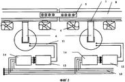
На фиг.1 изображен эскиз устройства; на фиг.2 изображен эскиз фрагмента устройства в укрупненном масштабе. Figure 1 shows a sketch of the device; figure 2 shows a sketch of a fragment of the device in an enlarged scale.
Устройство состоит из намагничивающей катушки 1, выполненной из изолированного провода, намотанного на каркас 2, внутри которого помещена средняя часть 3 П-образного магнитопровода, расположенных между шпалами 4 рельсошпальной решетки (РШР), соединенной с соседними рельсошпальными решетками немагнитными накладками 5. Боковые части магнитопровода 6, подсоединенными своими полюсами через электроизолирующие прокладки 7 к рельсам 8 РШР, по которым движутся колеса 9 локомотива, посаженные на ось колесной пары 10. Выводы 11 намагничивающей катушки 1 подключены к выходу блока электропитания 12, вход которого подключен к электропитающей сети 13 через блок автоматической регистрации (БАР) 14 нахождения локомотива на рельсах РШР. The device consists of a magnetizing coil 1 made of an insulated wire wound on a frame 2, inside of which is placed the middle part 3 of a U-shaped magnetic circuit located between the sleepers 4 of the rail-sleeper grid (RShR), connected to adjacent rail-sleeper grids by
Устройство работает следующим образом. The device operates as follows.
При подходе локомотива к РШР, оборудованной предлагаемым устройством, БАР 14 регистрирует этот факт и включает блок электропитания 12, к выходу которого подключены выводы 11 намагничивающей катушки 1. В катушке 1 начинает протекать рабочий ток, который создает магнитное поле, магнитно-силовые линии которого замыкаются по следующему пути: средняя часть 3 и одна из боковых частей 6 П-образного магнитопровода, один из рельсов 8 РШР, одно из колес 9 локомотива, далее частично через ось колесной пары 10, а частично через элементы конструкции тележки локомотива и буксы, второе колесо 9, второй рельс 8 РШР, вторую боковую часть 6 и среднюю часть 3 П-образного магнитопровода. Таким образом, весь магнитный поток, замыкаясь, проходит через места соприкосновения рельсов 8 и колес 9, в результате чего в этих местах происходит дополнительное прижимание колес к рельсам за счет их намагничивания, что повышает сцепление между ними. После прохода первой по ходу колесной парой локомотива стыка между рельсами РШР включается аналогичное устройство на следующей РШР, а когда последняя по ходу колесная пара локомотива пройдет этот стык, отключается устройство в РШР и далее процесс продолжается до тех пор, пока локомотивом не будет преодолен весь участок пути, оборудованный аналогичными устройствами. Такая очередность подключения устройств на участках железнодорожного пути необходима, например, при преодолении поездом затяжных крутых подъемов, так как если при этом не отключать устройства на РШР пройденных локомотивом участков пути, сцепление колес с рельсами будет возрастать для всех колесных пар буксируемых вагонов по мере их въезда на РШР, оборудованные устройствами, что будет создавать дополнительную нагрузку для локомотива. When approaching the locomotive to the RCS equipped with the proposed device, the
Предлагаемое изобретение имеет следующие преимущества:
- устройство может применяться для всех видов и типов локомотивов, в том числе и для паровозов на всех участках железных дорог, где есть электроэнергия;
- магнитное поле, создаваемое устройством, действует одновременно на все колесные пары локомотива;
- не требуется специальных доработок подвижного состава для использования устройства;
- за счет замкнутости магнитных цепей потоки рассеяния магнитных полей в устройстве имеют незначительную величину, что, в конечном итоге, повышает эффективность использования электроэнергии;
- все детали и узлы устройства функционируют в статическом состоянии, что повышает надежность их работы и снижает эксплуатационные затраты;
- возможность быстрого монтажа и демонтажа устройства без какой-либо реконструкции ЖД путей не требует привлечения для этого значительных финансовых и материальных ресурсов.The invention has the following advantages:
- the device can be used for all types and types of locomotives, including steam locomotives in all sections of railways where there is electricity;
- the magnetic field generated by the device acts simultaneously on all wheelsets of the locomotive;
- no special modifications of the rolling stock are required to use the device;
- due to the closure of the magnetic circuits, the fluxes of scattering of magnetic fields in the device are insignificant, which, ultimately, increases the efficiency of energy use;
- all parts and components of the device operate in a static state, which increases the reliability of their work and reduces operating costs;
- the ability to quickly assemble and disassemble the device without any reconstruction of the railway tracks does not require the attraction of significant financial and material resources.
Учитывая указанные преимущества, можно сделать вывод, что заявленное изобретение соответствует условию "промышленная применимость". Given these advantages, we can conclude that the claimed invention meets the condition of "industrial applicability".
Источники информации
[1] Патент Российской Федерации 2055748, кл. В 60 С 15/04, опубликован 10.03.96, БИ 7.Sources of information
[1] Patent of the Russian Federation 2055748, cl. B 60 C 15/04, published 03/10/96,
Claims (1)
Priority Applications (1)
| Application Number | Priority Date | Filing Date | Title |
|---|---|---|---|
| RU2001102093A RU2200103C2 (en) | 2001-01-25 | 2001-01-25 | Device to increase locomotive wheels-to-rails adhesion |
Applications Claiming Priority (1)
| Application Number | Priority Date | Filing Date | Title |
|---|---|---|---|
| RU2001102093A RU2200103C2 (en) | 2001-01-25 | 2001-01-25 | Device to increase locomotive wheels-to-rails adhesion |
Publications (2)
| Publication Number | Publication Date |
|---|---|
| RU2200103C2 true RU2200103C2 (en) | 2003-03-10 |
| RU2001102093A RU2001102093A (en) | 2003-04-10 |
Family
ID=20245153
Family Applications (1)
| Application Number | Title | Priority Date | Filing Date |
|---|---|---|---|
| RU2001102093A RU2200103C2 (en) | 2001-01-25 | 2001-01-25 | Device to increase locomotive wheels-to-rails adhesion |
Country Status (1)
| Country | Link |
|---|---|
| RU (1) | RU2200103C2 (en) |
Cited By (2)
| Publication number | Priority date | Publication date | Assignee | Title |
|---|---|---|---|---|
| RU2375220C1 (en) * | 2008-09-09 | 2009-12-10 | Государственное образовательное учреждение высшего профессионального образования "Пермский государственный университет" | Magnetic clamping device |
| CN114030491A (en) * | 2021-11-09 | 2022-02-11 | 上海市基础工程集团有限公司 | Traction device for moving reinforcement cage binding platform |
Citations (5)
| Publication number | Priority date | Publication date | Assignee | Title |
|---|---|---|---|---|
| SU31458A1 (en) * | 1932-08-12 | 1933-08-31 | И.П. Сунгуров | Rail butt joint |
| SU143426A1 (en) * | 1961-05-09 | 1961-11-30 | Л.П. Стрельников | Driving wheel of a miner locomotive |
| US3653329A (en) * | 1968-09-20 | 1972-04-04 | Hitachi Ltd | Electromagnetic traction increasing assembly |
| FR2519597A1 (en) * | 1982-01-12 | 1983-07-18 | Hubert Charles | Magnetic traction enhancement for railed vehicles - uses electrically excited coils mounted round axles to establish magnetic flux through rails and returning through next axle |
| RU2055748C1 (en) * | 1993-07-07 | 1996-03-10 | Борис Петрович Цалоев | Device to increase adhesion of electric locomotive wheelset with rails |
-
2001
- 2001-01-25 RU RU2001102093A patent/RU2200103C2/en not_active IP Right Cessation
Patent Citations (5)
| Publication number | Priority date | Publication date | Assignee | Title |
|---|---|---|---|---|
| SU31458A1 (en) * | 1932-08-12 | 1933-08-31 | И.П. Сунгуров | Rail butt joint |
| SU143426A1 (en) * | 1961-05-09 | 1961-11-30 | Л.П. Стрельников | Driving wheel of a miner locomotive |
| US3653329A (en) * | 1968-09-20 | 1972-04-04 | Hitachi Ltd | Electromagnetic traction increasing assembly |
| FR2519597A1 (en) * | 1982-01-12 | 1983-07-18 | Hubert Charles | Magnetic traction enhancement for railed vehicles - uses electrically excited coils mounted round axles to establish magnetic flux through rails and returning through next axle |
| RU2055748C1 (en) * | 1993-07-07 | 1996-03-10 | Борис Петрович Цалоев | Device to increase adhesion of electric locomotive wheelset with rails |
Cited By (2)
| Publication number | Priority date | Publication date | Assignee | Title |
|---|---|---|---|---|
| RU2375220C1 (en) * | 2008-09-09 | 2009-12-10 | Государственное образовательное учреждение высшего профессионального образования "Пермский государственный университет" | Magnetic clamping device |
| CN114030491A (en) * | 2021-11-09 | 2022-02-11 | 上海市基础工程集团有限公司 | Traction device for moving reinforcement cage binding platform |
Similar Documents
| Publication | Publication Date | Title |
|---|---|---|
| ES2198735T3 (en) | DRIVING SYSTEM FOR A MAGNETIC FLOATING VEHICLE. | |
| RU2461481C2 (en) | Railway electromagnetic brake with asymmetric excitation coil and/or composite coil | |
| RU2397093C2 (en) | Rail electromagnetic brake | |
| CN100396527C (en) | Magnetic track brake | |
| Tandan et al. | A review on development and analysis of maglev train | |
| EP1477382B1 (en) | Electrically operable magnetic rail brake device | |
| CN101985283A (en) | High speed maglev train guiding and eddy current braking integrative electromagnet device | |
| RU2200103C2 (en) | Device to increase locomotive wheels-to-rails adhesion | |
| CN102923159B (en) | A kind of electromagnetic magnetic rail brake | |
| RU2281216C1 (en) | Device to increase wheel-rail adhesion of locomotive driving wheels | |
| RU2185984C2 (en) | Rail brake with permanent magnets | |
| RU2749160C1 (en) | Device for magnetic treatment of rails and rail bars | |
| Martin et al. | Investigation of a linear induction machine for a railway braking application | |
| RU2732306C1 (en) | Valve-inductor electromechanical converter | |
| US1116283A (en) | Alternating-current-translating device. | |
| RU2001102093A (en) | DEVICE FOR INCREASING CLUTCH OF LOCOMOTIVE WHEELS WITH RAILS | |
| US1542902A (en) | Electromagnetic appliance for railways | |
| DE405638C (en) | Track magnet for train monitoring | |
| RU2658751C1 (en) | Power-generating device | |
| SU1498660A1 (en) | Method of applying magnetic markes onto railway vehicle wheel | |
| Korchagin et al. | Positioning of the inductor in magnetic coupling amplifiers of locomotive wheels with rails | |
| Stevens | Gab signals for railway signaling | |
| GB260344A (en) | Improvements relating to track braking devices for railway and like vehicles | |
| RU2645559C1 (en) | Electromagnetic rail brake with rail poles | |
| RU2370393C1 (en) | Path-control transducer |
Legal Events
| Date | Code | Title | Description |
|---|---|---|---|
| MM4A | The patent is invalid due to non-payment of fees |
Effective date: 20050126 |