RU2194673C2 - Aerotank - Google Patents
Aerotank Download PDFInfo
- Publication number
- RU2194673C2 RU2194673C2 RU2001100647/12A RU2001100647A RU2194673C2 RU 2194673 C2 RU2194673 C2 RU 2194673C2 RU 2001100647/12 A RU2001100647/12 A RU 2001100647/12A RU 2001100647 A RU2001100647 A RU 2001100647A RU 2194673 C2 RU2194673 C2 RU 2194673C2
- Authority
- RU
- Russia
- Prior art keywords
- liquid
- inclined partitions
- conical inclined
- units
- visors
- Prior art date
Links
Images

Classifications
-
- Y—GENERAL TAGGING OF NEW TECHNOLOGICAL DEVELOPMENTS; GENERAL TAGGING OF CROSS-SECTIONAL TECHNOLOGIES SPANNING OVER SEVERAL SECTIONS OF THE IPC; TECHNICAL SUBJECTS COVERED BY FORMER USPC CROSS-REFERENCE ART COLLECTIONS [XRACs] AND DIGESTS
- Y02—TECHNOLOGIES OR APPLICATIONS FOR MITIGATION OR ADAPTATION AGAINST CLIMATE CHANGE
- Y02W—CLIMATE CHANGE MITIGATION TECHNOLOGIES RELATED TO WASTEWATER TREATMENT OR WASTE MANAGEMENT
- Y02W10/00—Technologies for wastewater treatment
- Y02W10/10—Biological treatment of water, waste water, or sewage
Landscapes
- Aeration Devices For Treatment Of Activated Polluted Sludge (AREA)
Abstract
Description
Изобретение относится к обработке воды промышленных бытовых сточных вод. The invention relates to the treatment of industrial wastewater.
Известен аэротенк (см. а. с. 875768, МКИ C 02 F 3/02, Бюл. 26, 1982), содержащий корпус, наклонные перегородки с основными козырьками, узлы подачи исходной жидкости, ее аэрарии, отвода очищенной жидкости и избыточного ила. Known aeration tank (see and.with. 875768, MKI C 02
Недостатком данного аэротенка является недостаточно эффективное его использование из-за неравномерного смешения исходной жидкости с кислородом воздуха. The disadvantage of this aeration tank is its inefficient use due to the uneven mixing of the initial liquid with oxygen.
Известен аэротенк (см. а. c. 1392029, МКИ С 02 F 3/02, Бюл. 16, 1988), содержащий корпус, конусообразные наклонные перегородки с основными козырьками, узлы подачи исходной жидкости, ее аэрации, отвода очищенной жидкости и избыточного ила, колпаки с узлами подачи газожидкостной смеси, отвода газа и жидкости, дополнительные козырьки, соединенные с конусообразными наклонными перегородками и (или) основными козырьками с образованием колпаков, конусообразные наклонные перегородки расположены зигзагообразно, а дополнительные козырьки соединены с основными и расположены под узлами подачи газожидкостной смеси. Known aeration tank (see A. p. 1392029, MKI C 02
Недостатком данного аэротенка является недостаточно эффективное его использование из-за неполного окисления органических соединений. The disadvantage of this aeration tank is its inefficient use due to incomplete oxidation of organic compounds.
Технической задачей, на решение которой направлено предлагаемое изобретение, является повышение эффективности использования аэротенка путем установки в пространстве под нижними конусообразными наклонными перегородками с криволинейными циклоидальными кондукторами на их поверхности эжектора, на внутренней сопловой части которого предусмотрены криволинейные спиралевидные направляющие, соединенного при помощи гибких трубопроводов с кольцевой камерой, на поверхности которой установлены расширяющиеся насадки, направленные в чередующейся последовательности горизонтально и вертикально вверх, а на их внутренней поверхности предусмотрены криволинейные винтообразные канавки. The technical problem to which the invention is directed is to increase the efficiency of using the aeration tank by installing in the space under the lower conical inclined partitions with curved cycloidal conductors on their surface of the ejector, on the inner nozzle part of which there are curved spiral guides connected by flexible pipelines to the annular camera, on the surface of which are installed expanding nozzles directed in a series scheysya sequence horizontally and vertically, and on their inner surface are provided curved helical grooves.
Технический результат достигается тем, что аэротенк, содержащий корпус, конусообразные наклонные перегородки с основными козырьками, узлы подачи исходной жидкости, ее аэрации, отвода очищенной жидкости и избыточного ила, колпаки с узлами подачи газожидкостной смеси, отвода газа и жидкости, дополнительные козырьки, соединенные с конусообразными наклонными перегородками и/или основными козырьками с образованием колпаков, конусообразные наклонные перегородки расположены зигзагообразно, а дополнительные козырьки соединены с основными козырьками и расположены под узлами подачи газожидкостной смеси, имеет в пространстве под нижними конусообразными наклонными перегородками с криволинейными циклоидальными кондукторами на их поверхности эжектор, на внутренней поверхности сопловой части которого предусмотрены криволинейные спиралевидные направляющие, соединенный при помощи гибких трубопроводов с кольцевой камерой, на поверхности которой установлены расширяющиеся насадки, направленные в чередующейся последовательности горизонтально и вертикально вверх, а на их внутренней поверхности предусмотрены криволинейные винтообразные канавки. The technical result is achieved by the fact that the aeration tank containing the housing, cone-shaped inclined partitions with the main visors, nodes for supplying the original liquid, its aeration, removal of the purified liquid and excess sludge, caps with nodes for supplying a gas-liquid mixture, removal of gas and liquid, additional visors connected to conical inclined partitions and / or main visors with the formation of caps, conical inclined partitions are zigzag, and additional visors are connected to the main with holes and located under the nodes of the gas-liquid mixture supply, has an ejector in the space under the lower cone-shaped inclined partitions with curved cycloidal conductors on their surface, on the inner surface of the nozzle part of which there are curved spiral guides connected by flexible pipelines to an annular chamber on the surface of which expanding nozzles directed in an alternating sequence horizontally and vertically upwards, and on their inside Curved helical grooves are provided on the surface.
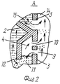
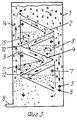
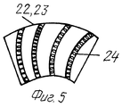
На фиг. 1 представлена схема аэротенка в разрезе, на фиг.2 - узел А, на фиг. 3 - вариант аэротенка с зигзагообразно расположенными конусообразными наклонными перегородками, на фиг.4 - эжектор с кольцевой камерой с расширяющимися насадками, а на фиг.5 - развертка внутренней поверхности расширяющихся насадок с криволинейными винтообразными канавками. In FIG. 1 shows a sectional view of the aeration tank, in FIG. 2, the assembly A, in FIG. 3 is an embodiment of an aeration tank with zigzag cone-shaped inclined partitions, FIG. 4 is an ejector with an annular chamber with expanding nozzles, and FIG. 5 is a scan of the inner surface of expanding nozzles with curved helical grooves.
Аэротенк круглой или прямоугольной формы в плане состоит из корпуса 1, конусообразных наклонных перегородок 2, расположенных одна над другой, с основными козырьками 3, колпаков 4, узлов 5 подачи исходной жидкости, узлов 6 ее аэрации, узла 7 отвода очищенной жидкости и узла 8 отвода избыточного ила. Колпаки 4 снабжены узлами 9 подачи газожидкостной смеси, узлами 10 отвода газа и узлами 11 отвода жидкости. Колпаки 4 образованы дополнительными козырьками 12, соединенными с конусообразными наклонными перегородками 2 или основными козырьками 3. Конусообразные наклонные перегородки 2 верхними концами присоединена к вертикальной перегородке 13. Объем аэротенка разделен основными козырьками 3 и вертикальными перегородками 13 на камеры 14 аэрации, которые соединены гидравлически в верхних и нижних частях, и камеры 15 осветления. Камеры 15 осветления разделены конусообразными наклонными перегородками 2 на ярусы. Узел 7 отвода очищенной жидкости расположен под верхними концами каждой конусообразной наклонной перегородки 2. В аэротенке прямоугольной формы в плане наклонные перегородки 2 выполнены не конусообразно. A circular or rectangular aeration tank in plan consists of a
В варианте с зигзагообразным расположением перегородок аэротенк прямоугольной формы состоит из корпуса 1, наклонных перегородок 2, расположенных зигзагообразно с основными козырьками 3, колпаков 4, узла 5 подачи исходной жидкости, узла 6 ее аэрации, узла 7 отвода очищенной жидкости и узла 8 отвода избыточного ила. Колпаки 4 снабжены узлами 9 подачи газожидкостной смеси, узлами 10 отвода газа и узлами 11 отвода жидкости. Колпаки 4 оборудованы дополнительными козырьками 12, соединенными с основными козырьками 3 и расположенными под узлами 9 подачи газожидкостной смеси. In a variant with a zigzag arrangement of partitions, a rectangular aeration tank consists of a
Объем аэротенка разделен козырьками 3 на камеры 14 аэрации, соединенные гидравлически в верхней и нижней частях, и камеру 15 осветления, разделенную наклонными перегородками 2 на ярусы. Узел 7 отвода очищенной жидкости расположен под верхним концом дополнительного козырька 12. The volume of the aeration tank is divided by the
В пространстве под нижними наклонными перегородками 2 с криволинейными циклоидальными кондукторами 16 на их поверхности установлен эжектор 17, на внутренней поверхности сопловой части 18 которого предусмотрены криволинейное спиралевидные направляющие 19. Эжектор 17 при помощи гибких трубопроводов 20 соединен с кольцевой камерой 21, на поверхности которой установлены расширяющиеся насадки 22 и 23, направленные в чередующейся последовательности горизонтально 22 и вертикально 23 вверх. Причем горизонтально 22 направленные расширяющиеся насадки расположены тангенциально к кольцевой камере 21. На внутренней поверхности расширяющихся насадок 22 и 23 предусмотрены криволинейные винтообразные канавки 24. Узел 5 подачи исходной жидкости подведен к камере смешения 25 эжектора 17. Узел 6 аэрации исходной жидкости подведен к сопловой части 18 эжектора 17. In the space under the lower
Аэротенк работает следующим образом. Aerotank works as follows.
Сточные воды через узел 5 подачи исходной жидкости и через узел 6 ее аэрации подводятся к эжектору 17, расположенному в пространстве под нижними наклонными перегородками 2 с криволинейными циклоидальными кондукторами 16. Причем исходная жидкость поступает в камеру смешения 25 эжектора 17, а кислородосодержащий газ - в сопловую часть 18 с криволинейными спиралевидными направляющими 19. При этом эжектор 17 за счет аэродинамических сил кислородосодержащего газа создает разрежение (вакуум) и обеспечивает подсос исходной жидкости, а криволинейные спиралевидные направляющие 19 на внутренней поверхности сопловой части 18 эжектора 17 за счет закрутки потока исходной жидкости интенсивно перемешивают активный ил со сточными водами. Далее смесь сточных вод, кислородосодержащего газа и активного ила попадают через гибкие трубопроводы 20, которые, вибрируя, способствуют эмульгированию смеси жидкости и газов, в кольцевую камеру 21, на поверхности которой в чередующейся последовательности установлены горизонтально 22 и вертикально 23 вверх расширяющиеся насадки с криволинейными винтообразными канавками 24 на их внутренней поверхности, в которых проходящая по ним смесь закручивается. Интенсивному диспергированию и перемешиванию компонентов смеси сточных вод, кислородосодержащего газа и активного ила способствует расположение расширяющихся насадок горизонтально 22 и вертикально 23 вверх в чередующейся последовательности и тангенциальное подключение горизонтально 22 расположенных расширяющихся насадок к поверхности кольцевой камеры 21. Выходящая из расширяющихся насадок 22 и 23 смесь, имеющая центробежные силы за счет закрутки потока, выбрасывается и попадает на поверхность нижних наклонных перегородок 2, на которой имеются криволинейные циклоидальные кондукторы 16, создающие дополнительное завихрение потока сминимальными энергетическими затратами за счет свойств циклоиды, направляют смесь в камеру аэрации 14, где она циркулирует, аэрирует и окисляет органические соединения. Смесь, имея меньшую плотность, чем исходная жидкость, устремляется в верхнюю часть аэротенка и опускается вниз, перемещаясь по наклонным перегородкам. При этом образуются зоны осветления, разделения на фазы и осуществляется отвод отдельных компонентов через соответствующие узлы. Wastewater through the
Создание закрутки потока исходной жидкости, способствующей интенсивному перемешиванию сточных вод, кислородосодержащего газа и активного ила, глубоко эмульгированной смеси, имеющей меньшей плотность, чем исходная жидкость, усеивает ее циркуляцию, интенсифицирует окисление органических соединений аэробными бактериями во всем объеме аэротенка и повышает эффективность использования аэротенка. Creating a swirl of the flow of the initial liquid, which facilitates intensive mixing of wastewater, oxygen-containing gas and activated sludge, a deeply emulsified mixture having a lower density than the initial liquid, strengthens its circulation, intensifies the oxidation of organic compounds by aerobic bacteria throughout the aerotank and increases the efficiency of using the aeration tank.
Оригинальность предлагаемого технического решения заключается в использовании эффекта закрутки потока путем создания глубоко эмульгированной эмульсии, при которой интенсифицируются процессы циркуляции и окисления органических соединений аэробными бактериями для повышения эффективности использования аэротенка. The originality of the proposed technical solution consists in using the effect of swirling the flow by creating a deeply emulsified emulsion, in which the processes of circulation and oxidation of organic compounds by aerobic bacteria are intensified to increase the efficiency of use of the aeration tank.
Claims (1)
Priority Applications (1)
| Application Number | Priority Date | Filing Date | Title |
|---|---|---|---|
| RU2001100647/12A RU2194673C2 (en) | 2001-01-09 | 2001-01-09 | Aerotank |
Applications Claiming Priority (1)
| Application Number | Priority Date | Filing Date | Title |
|---|---|---|---|
| RU2001100647/12A RU2194673C2 (en) | 2001-01-09 | 2001-01-09 | Aerotank |
Publications (2)
| Publication Number | Publication Date |
|---|---|
| RU2194673C2 true RU2194673C2 (en) | 2002-12-20 |
| RU2001100647A RU2001100647A (en) | 2003-01-27 |
Family
ID=20244559
Family Applications (1)
| Application Number | Title | Priority Date | Filing Date |
|---|---|---|---|
| RU2001100647/12A RU2194673C2 (en) | 2001-01-09 | 2001-01-09 | Aerotank |
Country Status (1)
| Country | Link |
|---|---|
| RU (1) | RU2194673C2 (en) |
Cited By (2)
| Publication number | Priority date | Publication date | Assignee | Title |
|---|---|---|---|---|
| RU2731501C1 (en) * | 2019-12-11 | 2020-09-03 | Федеральное государственное бюджетное образовательное учреждение высшего образования. "Юго-Западный государственный университет" (ЮЗГУ) | Gas-distributing station |
| CN119912098A (en) * | 2025-02-05 | 2025-05-02 | 浙江省二建建设集团有限公司 | A device and method for efficiently reducing iron ions in water |
Citations (3)
| Publication number | Priority date | Publication date | Assignee | Title |
|---|---|---|---|---|
| SU1392029A1 (en) * | 1986-12-22 | 1988-04-30 | Bazhenov Nikolaj G | Aerotank |
| RU2135705C1 (en) * | 1997-12-03 | 1999-08-27 | Курский государственный технический университет | Device for circulation treatment of well for water |
| RU2144414C1 (en) * | 1998-08-11 | 2000-01-20 | Курский государственный технический университет | Water treatment plant |
-
2001
- 2001-01-09 RU RU2001100647/12A patent/RU2194673C2/en active
Patent Citations (3)
| Publication number | Priority date | Publication date | Assignee | Title |
|---|---|---|---|---|
| SU1392029A1 (en) * | 1986-12-22 | 1988-04-30 | Bazhenov Nikolaj G | Aerotank |
| RU2135705C1 (en) * | 1997-12-03 | 1999-08-27 | Курский государственный технический университет | Device for circulation treatment of well for water |
| RU2144414C1 (en) * | 1998-08-11 | 2000-01-20 | Курский государственный технический университет | Water treatment plant |
Cited By (2)
| Publication number | Priority date | Publication date | Assignee | Title |
|---|---|---|---|---|
| RU2731501C1 (en) * | 2019-12-11 | 2020-09-03 | Федеральное государственное бюджетное образовательное учреждение высшего образования. "Юго-Западный государственный университет" (ЮЗГУ) | Gas-distributing station |
| CN119912098A (en) * | 2025-02-05 | 2025-05-02 | 浙江省二建建设集团有限公司 | A device and method for efficiently reducing iron ions in water |
Similar Documents
| Publication | Publication Date | Title |
|---|---|---|
| FI89703C (en) | Device for the treatment of liquids, especially waste water | |
| RU2116263C1 (en) | Reactor for biologically cleaning waste waters | |
| KR20110088355A (en) | Gas-liquid Mixing Circulation Generator | |
| CN103977602B (en) | Gas-liquid separation device and the sewage-treatment plant with this gas-liquid separation device | |
| US4211657A (en) | Means for biological treatment of water | |
| KR102131677B1 (en) | Guide module and micro bubble generator for wastewater treatment provided with the same | |
| RU2194673C2 (en) | Aerotank | |
| KR102562116B1 (en) | Advenced oxidation apparatus using micro-bubble and high concentration organic wast water treatment system having the same | |
| JP2002045667A (en) | Circulating flow generator | |
| KR100437971B1 (en) | Mixer for mixing fluids and electrolytic water treatment system having the same | |
| RU2002109789A (en) | Method and device for biological wastewater treatment | |
| JP4374885B2 (en) | Membrane separator | |
| RU2114063C1 (en) | Water flotation treatment plant | |
| RU96100512A (en) | FLOTATION MACHINE FOR SEWAGE TREATMENT | |
| JP4819841B2 (en) | Membrane separator | |
| RU48531U1 (en) | AEROTENC FOR SEWAGE TREATMENT | |
| JP2019093375A (en) | Air mixing nozzle | |
| RU2197437C2 (en) | Sewage water purifying apparatus | |
| RU95100001A (en) | Method and plant for treatment of sewage to remove suspended fibrous impurities | |
| JP4342687B2 (en) | Wastewater treatment equipment | |
| KR100968752B1 (en) | Multi aeration-mixing machine | |
| RU2081578C1 (en) | Aerator and fermenter with aerating and fermenting apparatus | |
| RU120095U1 (en) | DEVICE FOR BIOLOGICAL SEWAGE TREATMENT | |
| RU2193017C2 (en) | Aerotank for sewage water treatment | |
| JP2925831B2 (en) | Filtration device |