RU2191471C2 - Satellite communication system using encoding with parallel integration - Google Patents
Satellite communication system using encoding with parallel integration Download PDFInfo
- Publication number
- RU2191471C2 RU2191471C2 RU97112743/09A RU97112743A RU2191471C2 RU 2191471 C2 RU2191471 C2 RU 2191471C2 RU 97112743/09 A RU97112743/09 A RU 97112743/09A RU 97112743 A RU97112743 A RU 97112743A RU 2191471 C2 RU2191471 C2 RU 2191471C2
- Authority
- RU
- Russia
- Prior art keywords
- communication system
- code
- encoder
- parallel
- encoding
- Prior art date
Links
Images


Classifications
-
- H—ELECTRICITY
- H04—ELECTRIC COMMUNICATION TECHNIQUE
- H04B—TRANSMISSION
- H04B7/00—Radio transmission systems, i.e. using radiation field
- H04B7/14—Relay systems
- H04B7/15—Active relay systems
- H04B7/185—Space-based or airborne stations; Stations for satellite systems
- H04B7/18528—Satellite systems for providing two-way communications service to a network of fixed stations, i.e. fixed satellite service or very small aperture terminal [VSAT] system
-
- H—ELECTRICITY
- H04—ELECTRIC COMMUNICATION TECHNIQUE
- H04L—TRANSMISSION OF DIGITAL INFORMATION, e.g. TELEGRAPHIC COMMUNICATION
- H04L1/00—Arrangements for detecting or preventing errors in the information received
- H04L1/004—Arrangements for detecting or preventing errors in the information received by using forward error control
- H04L1/0056—Systems characterized by the type of code used
- H04L1/0064—Concatenated codes
- H04L1/0065—Serial concatenated codes
-
- H—ELECTRICITY
- H03—ELECTRONIC CIRCUITRY
- H03M—CODING; DECODING; CODE CONVERSION IN GENERAL
- H03M13/00—Coding, decoding or code conversion, for error detection or error correction; Coding theory basic assumptions; Coding bounds; Error probability evaluation methods; Channel models; Simulation or testing of codes
- H03M13/29—Coding, decoding or code conversion, for error detection or error correction; Coding theory basic assumptions; Coding bounds; Error probability evaluation methods; Channel models; Simulation or testing of codes combining two or more codes or code structures, e.g. product codes, generalised product codes, concatenated codes, inner and outer codes
- H03M13/2957—Turbo codes and decoding
- H03M13/2996—Tail biting
-
- H—ELECTRICITY
- H04—ELECTRIC COMMUNICATION TECHNIQUE
- H04B—TRANSMISSION
- H04B7/00—Radio transmission systems, i.e. using radiation field
- H04B7/14—Relay systems
- H04B7/15—Active relay systems
- H04B7/185—Space-based or airborne stations; Stations for satellite systems
- H04B7/18578—Satellite systems for providing broadband data service to individual earth stations
- H04B7/1858—Arrangements for data transmission on the physical system, i.e. for data bit transmission between network components
-
- H—ELECTRICITY
- H04—ELECTRIC COMMUNICATION TECHNIQUE
- H04L—TRANSMISSION OF DIGITAL INFORMATION, e.g. TELEGRAPHIC COMMUNICATION
- H04L1/00—Arrangements for detecting or preventing errors in the information received
- H04L1/004—Arrangements for detecting or preventing errors in the information received by using forward error control
- H04L1/0056—Systems characterized by the type of code used
- H04L1/0064—Concatenated codes
- H04L1/0066—Parallel concatenated codes
-
- H—ELECTRICITY
- H04—ELECTRIC COMMUNICATION TECHNIQUE
- H04L—TRANSMISSION OF DIGITAL INFORMATION, e.g. TELEGRAPHIC COMMUNICATION
- H04L1/00—Arrangements for detecting or preventing errors in the information received
- H04L1/004—Arrangements for detecting or preventing errors in the information received by using forward error control
- H04L1/0056—Systems characterized by the type of code used
- H04L1/0067—Rate matching
- H04L1/0068—Rate matching by puncturing
-
- H—ELECTRICITY
- H03—ELECTRONIC CIRCUITRY
- H03M—CODING; DECODING; CODE CONVERSION IN GENERAL
- H03M13/00—Coding, decoding or code conversion, for error detection or error correction; Coding theory basic assumptions; Coding bounds; Error probability evaluation methods; Channel models; Simulation or testing of codes
- H03M13/29—Coding, decoding or code conversion, for error detection or error correction; Coding theory basic assumptions; Coding bounds; Error probability evaluation methods; Channel models; Simulation or testing of codes combining two or more codes or code structures, e.g. product codes, generalised product codes, concatenated codes, inner and outer codes
- H03M13/2957—Turbo codes and decoding
- H03M13/296—Particular turbo code structure
- H03M13/2966—Turbo codes concatenated with another code, e.g. an outer block code
Landscapes
- Engineering & Computer Science (AREA)
- Computer Networks & Wireless Communication (AREA)
- Signal Processing (AREA)
- Physics & Mathematics (AREA)
- Astronomy & Astrophysics (AREA)
- Aviation & Aerospace Engineering (AREA)
- General Physics & Mathematics (AREA)
- Probability & Statistics with Applications (AREA)
- Theoretical Computer Science (AREA)
- Error Detection And Correction (AREA)
- Radio Relay Systems (AREA)
Abstract
Description
Изобретение относится к спутниковым системам связи и, в частности, к связным системам с терминалами, имеющими очень малую апертуру, в которых применяется кодирование с параллельным объединением в их входящих или исходящих линиях или и в тех и других линиях. The invention relates to satellite communication systems and, in particular, to communication systems with terminals having a very small aperture, in which coding is used with parallel combination in their incoming or outgoing lines, or both.
В настоящее время формируется рынок мультимедийной связи через спутники с использованием недорогих терминалов с очень малой апертурой (ТОМА, VSAT's, veri small aperture terminals). Преимущества использования антенн с размерами, меньшими, чем сегодня в большинстве случаев используются на практике, заключаются в снижении стоимости рефлектора, низкой стоимости перевозки, сокращении объема установочных работ и оборудования, необходимого для установки, и лучшей приспособленности для пользователя, обусловленной меньшими размерами устройства. Currently, a market for multimedia communications via satellites is being formed using inexpensive terminals with a very small aperture (TOMA, VSAT's, veri small aperture terminals). The advantages of using antennas with sizes smaller than today in most cases are used in practice are reduced reflector costs, low transportation costs, reduced installation work and equipment required for installation, and better fitness for the user due to the smaller size of the device.
В то же время, использование зеркальных антенн с малой апертурой может привести к нежелательному снижению пропускной способности сети. Это обусловливается несколькими причинами, связанными со снижением размеров антенны: (1) снижением мощности принимаемого и передаваемого сигнала вследствие соответствующего падения коэффициента усиления антенны; (2) рекомендациями Федеральной комиссии по связи (ФКС, FCC, Federal Communications Commission), ограничивающими мощность, передаваемую ТОМА с антеннами меньше определенных размеров, для ограничения плотности потока мощности взаимных помех в смежных орбитальных участках. Использование в ТОМА усилителей мощности с той же самой или меньшей выходной мощностью для сокращения стоимости ТОМА также приводит к снижению пропускной способности сети, вызванной энергетическими ограничениями. At the same time, the use of small aperture reflector antennas can lead to an undesirable reduction in network bandwidth. This is due to several reasons associated with a decrease in antenna size: (1) a decrease in the power of the received and transmitted signal due to a corresponding decrease in the antenna gain; (2) recommendations of the Federal Communications Commission (FCC, FCC, Federal Communications Commission), limiting the power transmitted by TOMA with antennas smaller than certain sizes, to limit the power flux density of mutual interference in adjacent orbital areas. The use of power amplifiers in TOMA with the same or lower output power to reduce the cost of TOMA also leads to a decrease in network bandwidth caused by energy restrictions.
К сожалению в коротких информационных блоках (характерных для некоторых типов передач с использованием ТОМА) весьма сложно получить необходимый коэффициент усиления за счет кодирования, позволяющий с применением обычных способов кодирования разрешить вышеупомянутые проблемы с требуемой эффективностью использования полосы частот и сложностью декодера. Unfortunately, in short information blocks (typical for some types of transmissions using TOMA) it is very difficult to obtain the necessary gain due to coding, which allows using the usual coding methods to solve the above problems with the required bandwidth efficiency and decoder complexity.
Таким образом, возникает необходимость в разработке системы спутниковой связи, обеспечивающей повышение пропускной способности сети при использовании ТОМА с уменьшенной апертурой антенны за счет снижения требуемого отношения энергии, приходящейся на один бит, к спектральной плотности шума Eb/No с применением способов с высокой спектральной эффективностью.Thus, there is a need to develop a satellite communications system that provides increased network throughput when using TOMA with a reduced antenna aperture by reducing the required ratio of energy per bit to noise spectral density E b / No using methods with high spectral efficiency .
В соответствии с представленным изобретением в спутниковой сети связи с ТОМА используется кодирование с параллельным объединением на входящих или исходящих линиях, либо на тех и на других линиях. В одном варианте реализации для кодирования коротких информационных блоков, типичных для пакетной передачи, действий с кредитными картами и для передачи сжатого речевого сигнала, в качестве составляющих кодов в схеме кодирования с параллельным объединением используются нерекурсивные систематические сверточные коды с добавлением битов в конец. Для более длинных информационных блоков, типичных для передачи данных, в ТОМА и в центральных терминалах сети используются рекурсивные систематические сверточные коды. In accordance with the present invention, satellite communication network with TOMA uses coding with parallel combining on incoming or outgoing lines, or on those and other lines. In one embodiment, non-recursive systematic convolutional codes with the addition of bits to the end are used as encoding schemes for encoding short information blocks, typical for packet transmission, credit card operations, and for transmitting a compressed speech signal. For longer information blocks, typical for data transmission, recursive systematic convolutional codes are used in TOMA and in the central terminals of the network.
В предпочтительном варианте реализации изобретения вышеупомянутый способ кодирования с параллельным объединением используется в сочетании с модуляцией с расширением спектра, в результате чего получается система, удовлетворяющая ограничениям ФКС на общую спектральную плотность потока мощности передаваемого сигнала, и снижаются взаимные помехи от соседних спутников. In a preferred embodiment of the invention, the aforementioned parallel combining coding method is used in combination with spread spectrum modulation, resulting in a system that satisfies the FCC restrictions on the total spectral power density of the transmitted signal power and reduces interference from neighboring satellites.
Признаки и преимущества настоящего изобретения станут более понятными из последующего подробного описания изобретения со ссылками на сопутствующие чертежи, где:
фиг. 1 изображает упрощенную структурную схему, иллюстрирующую систему связи с ТОМА, в которой применяется кодирование с параллельным объединением в соответствии с настоящим изобретением;
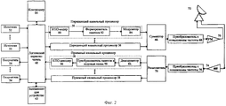
фиг. 2 - упрощенную структурную схему, иллюстрирующую центральный терминал спутниковой системы связи, в котором применяется кодирование с параллельным объединением в соответствии с настоящим изобретением;
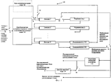
фиг. 3 - упрощенную структурную схему, иллюстрирующую программируемый кодер, используемый в системе связи с ТОМА в соответствии с настоящим изобретением;
фиг.4 - упрощенную структурную схему, иллюстрирующую программируемый декодер, применяемый в системе связи с ТОМА в соответствии с настоящим изобретением.The features and advantages of the present invention will become more apparent from the following detailed description of the invention with reference to the accompanying drawings, where:
FIG. 1 is a simplified block diagram illustrating a TOMA communication system that utilizes parallel combining in accordance with the present invention;
FIG. 2 is a simplified block diagram illustrating a central terminal of a satellite communications system in which parallel combining is used in accordance with the present invention;
FIG. 3 is a simplified block diagram illustrating a programmable encoder used in a TOMA communication system in accordance with the present invention;
4 is a simplified block diagram illustrating a programmable decoder used in a communication system with TOMA in accordance with the present invention.
Описываемая далее система представляет собой спутниковую систему связи с ТОМА, в которой применяются способ кодирования с параллельным объединением, например сверточное кодирование с параллельным объединением и с добавлением битов в конец, а также рекурсивное систематическое сверточное кодирование с параллельным обединением (так называемое "турбо"-кодирование) с соответствующими декодерами. В частности, для сверточных кодов с параллельным объединением и добавлением битов в конец применяется декодер, в котором используется циркулярное декодирование с максимальной апостериорной вероятностью, подобное описанному в заявке на американский патент, рассматриваемой вместе с настоящей заявкой и присоединяемой по ссылке: No.08/636742 авторов Stephen M. Hladik и John B.Anderson, поданной 19 апреля 1996. The system described below is a satellite communication system with TOMA, which uses a parallel combining coding method, for example convolutional coding with parallel combining and adding bits to the end, as well as recursive systematic convolutional coding with parallel combining (the so-called “turbo” coding ) with appropriate decoders. In particular, for convolutional codes with parallel combining and adding bits to the end, a decoder is used that uses circular decoding with maximum posterior probability, similar to that described in the application for US patent, considered together with this application and attached by reference: No.08 / 636742 authors Stephen M. Hladik and John B. Anderson, filed April 19, 1996.
Кодирование с параллельным объединением используется на входящих линиях передачи (ТОМА-центральный терминал) или на исходящих линиях передачи (центральный терминал-ТОМА), либо на обеих линиях спутниковой сети связи с ТОМА. Кроме того, кодирование с параллельным объединением может быть использовано для обеспечения кодирования с исправлением ошибок при непосредственной одноуровневой (ТОМА-ТОМА) передаче. В одном варианте реализации для кодирования коротких информационных блоков, типичных для пакетной передачи, действий с кредитными картами и для передачи сжатого речевого сигнала, в качестве составляющих кодов в схеме кодирования с параллельным объединением используются нерекурсивные систематические сверточные коды с добавлением битов в конец. Для более длинных информационных блоков, типичных для передачи данных, в ТОМА и в центральных терминалах сети используются рекурсивные систематические сверточные коды. Coding with parallel combining is used on incoming transmission lines (TOMA-central terminal) or on outgoing transmission lines (central terminal-TOMA), or on both lines of a satellite communication network with TOMA. In addition, parallel combining coding can be used to provide error correction coding for direct single-level (TOMA-TOMA) transmission. In one embodiment, non-recursive systematic convolutional codes with the addition of bits to the end are used as encoding schemes for encoding short information blocks, typical for packet transmission, credit card operations, and for transmitting a compressed speech signal. For longer information blocks, typical for data transmission, recursive systematic convolutional codes are used in TOMA and in the central terminals of the network.
В соответствии с настоящим изобретением использование данного способа кодирования с параллельным объединением в сочетании с модуляцией с расширенным спектром позволяет получить весьма эффективное решение, удовлетворяющее вышеупомянутым ограничениям, накладываемым ФКС на взаимные помехи от соседних спутников, за счет снижения требуемой эффективной излучаемой мощности (ЗИМ) и спектральной плотности мощности передаваемого сигнала. Кроме того, это сочетание позволяет снизить взаимные помехи от соседних спутников. In accordance with the present invention, the use of this parallel combining coding method in combination with spread spectrum modulation provides a very efficient solution that satisfies the aforementioned restrictions imposed by the FCC on mutual interference from neighboring satellites by reducing the required effective radiated power (ZIM) and spectral power density of the transmitted signal. In addition, this combination reduces interference from neighboring satellites.
На фиг. 1 представлена структурная схема спутниковой системы связи с ТОМА, в которой применяется кодирование с параллельным объединением в соответствии с настоящим изобретением. Данная система в общем случае содержит несколько терминалов ТОМА 10, спутник 12 со связным приемоответчиком, а также, возможно, центральный терминал 14. Связь в пределах сети с ТОМА может быть односторонней или двухсторонней и может осуществляться различными путями: (1) непосредственно ТОМА-ТОМА (т. е. сетевая связь) и (2) ТОМА-центральный терминал и/или центральный терминал-ТОМА (т.е. связь по звездообразной схеме). In FIG. 1 is a structural diagram of a satellite communication system with TOMA, in which coding with parallel combining is used in accordance with the present invention. This system generally contains several TOMA 10 terminals, satellite 12 with a connected transponder, and possibly a central terminal 14. Communication within the network with TOMA can be one-way or two-way and can be carried out in various ways: (1) directly TOMA-TOMA (i.e. network communication) and (2) TOMA-central terminal and / or central terminal-TOMA (i.e. star-shaped communication).
Как показано на фиг.1, терминал ТОМА 10 включает блок обработки передаваемых сигналов 20, блок обработки принимаемых сигналов 22 и антенну 24. В соответствии с раскрываемым изобретением блок обработки передаваемых сигналов ТОМА содержит: входной порт 25 для приема данных от источника информации 26; кодер 28, который осуществляет кодирование с параллельным объединением блоков данных, поступающих из источника; формирователь пакетов 30, предназначенный для получения пакетов данных (содержащих одно или более кодовых слов с кодера 28), синхронизирующей битовой последовательности и управляющих битов сигнализации; модулятор 32; переносчик с повышением частоты 34, предназначенный для переноса модулированного сигнала на частоту несущей с целью передачи модулированных сигналов от антенны к космическому аппарату; усилитель мощности 36 и соединение с антенной 24 через соответствующее согласующее устройство (например, переключатель или антенный переключатель с фильтром). As shown in FIG. 1, the TOMA terminal 10 includes a transmitted signal processing unit 20, a received signal processing unit 22, and an antenna 24. In accordance with the disclosed invention, the TOMA transmitted signal processing unit includes: an input port 25 for receiving data from an information source 26; an encoder 28 that encodes in parallel combining data blocks coming from a source; a packetizer 30, designed to receive data packets (containing one or more code words from encoder 28), a synchronizing bit sequence and control signaling bits; modulator 32; a frequency increasing carrier 34 for transmitting a modulated signal to a carrier frequency in order to transmit modulated signals from an antenna to a spacecraft; a power amplifier 36 and connection to the antenna 24 through an appropriate matching device (for example, a switch or an antenna switch with a filter).
Модулированные сигналы, перенесенные на сигнал несущей, принимают от космического аппарата на антенну и посредством антенного переключателя подают в блок обработки принимаемых сигналов ТОМА, который содержит малошумящий усилитель 40; преобразователь с понижением частоты 42, предназначенный для переноса принимаемого сигнала с частоты несущей на промежуточную частоту, демодулятор 44 для синхронизации и демодуляции; формирователь кодовых слов из пакетов 46, декодер 48, обеспечивающий декодирование сигналов с кодированием с параллельным объединением, которое применяется в передатчике, а также выходной порт 49 для передачи принимаемых сообщений (т.е. блоков информационных битов) получателю информации 50. Для краткости на фиг.1 показана подробная структурная схема для единственного ТОМА. Modulated signals transferred to the carrier signal are received from the spacecraft to the antenna and, through the antenna switch, are fed to the received signal processing unit TOMA, which contains a low-noise amplifier 40; a down-converter 42 for transferring a received signal from a carrier frequency to an intermediate frequency; a demodulator 44 for synchronization and demodulation; a codeword generator from packets 46, a decoder 48, which provides decoding of signals with encoding with parallel combining, which is used in the transmitter, as well as an output port 49 for transmitting received messages (i.e. blocks of information bits) to the information receiver 50. For brevity, in FIG. .1 shows a detailed block diagram for a single TOMA.
Функции синхронизации, выполняемые демодулятором 44, включают настройку на частоту несущей, кадровую синхронизацию, посимвольную синхронизацию и, при необходимости, синхронизацию по фазе несущей. Посимвольная синхронизация представляет собой процедуру нахождения наилучшего времени выборки (т.е. времени появления символа) на выходе демодулятора с целью минимизации вероятности ошибочного приема символа. Кадровая синхронизация заключается в оценивании времени появления символа для первого символа в кадре принимаемых данных (для непрерывной передачи) или пакета (для прерывистой передачи). The synchronization functions performed by the demodulator 44 include tuning to the carrier frequency, frame synchronization, character-by-symbol synchronization, and, if necessary, carrier phase synchronization. Symbol-by-symbol synchronization is the procedure for finding the best sampling time (i.e., the time a symbol appears) at the output of a demodulator in order to minimize the likelihood of an erroneous symbol reception. Frame synchronization consists in estimating the time of occurrence of a symbol for the first symbol in a frame of received data (for continuous transmission) or a packet (for intermittent transmission).
В случае, когда ТОМА передает сигналы с расширенным спектром, модулятор ТОМА, показанный на фиг.1, осуществляет функции расширения спектра, а демодулятор ТОМА, показанный на фиг.1, осуществляет функции сужения спектра. Способ расширения спектра приводит к увеличению полосы сигнала по сравнению с шириной спектра модулированного информационного сигнала за счет наложения расширяющего сигнала, содержащего элементарные сигнальные посылки (в случае расширения спектра прямой последовательностью) или перескоки (в случае расширения спектра с перескоками частоты), которые являются псевдослучайными и не зависят от информационного сигнала. При расширении спектра прямой последовательностью информационный сигнал умножается на сигнал, соответствующий псевдослучайной последовательности элементарных сигнальных посылок, принимающих значения +1 или -1. Длительность элементарной сигнальной посылки меньше, чем период передачи символа модулированного информационного сигнала, в результате чего полоса спектра результирующего сигнала превышает полосу исходного модулированного сигнала. При расширении спектра с перескоками частоты несущая модулированного сигнала периодически изменяется по псевдослучайному закону. Как и прежде, полоса спектра расширенного сигнала превышает полосу исходного модулированного сигнала. In the case where TOMA transmits spread spectrum signals, the TOMA modulator shown in FIG. 1 performs spectrum spreading functions, and the TOMA demodulator shown in FIG. 1 performs spectrum narrowing functions. The method of spreading the spectrum leads to an increase in the signal bandwidth compared to the spectrum width of the modulated information signal due to the superposition of the spreading signal containing elementary signal parcels (in the case of spreading the spectrum by a direct sequence) or hopping (in the case of spreading the spectrum with frequency jumps), which are pseudo-random independent of the information signal. When the spectrum is expanded by a direct sequence, the information signal is multiplied by a signal corresponding to a pseudo-random sequence of elementary signal packets taking the values +1 or -1. The duration of the elementary signal transmission is less than the period of transmission of the symbol of the modulated information signal, as a result of which the spectrum bandwidth of the resulting signal exceeds the bandwidth of the original modulated signal. When expanding the spectrum with frequency hopping, the carrier of the modulated signal periodically changes according to the pseudo-random law. As before, the bandwidth of the spread signal exceeds the bandwidth of the original modulated signal.
Сужение спектра в демодуляторе заключается в устранении расширения спектра принимаемого сигнала. Обычно демодулятор коррелирует принимаемый сигнал с репликой расширяющего сигнала для сужения спектра сигнала со спектром, расширенным прямой последовательностью, а в системах с расширением спектра за счет перескоков частоты осуществляется скачкообразная перестройка частоты задающего генератора в преобразователе с понижением частоты приемника и при этом используется тот же закон перестройки, что и на передающем терминале для расширения спектра за счет перескоков частоты. Обычно для ослабления широкополосного шума и помеховых составляющих в принимаемом сигнале после сужения спектра используется фильтр. The narrowing of the spectrum in the demodulator is to eliminate the expansion of the spectrum of the received signal. Typically, a demodulator correlates the received signal with a replica of the spreading signal to narrow the spectrum of the signal with a spectrum expanded by a direct sequence, and in systems with spreading of the spectrum due to frequency hopping, frequency hopping of the master oscillator in the converter with decreasing receiver frequency is used and the same tuning law is used as on the transmitting terminal for spreading the spectrum due to frequency hopping. Typically, a filter is used to attenuate broadband noise and interfering components in the received signal after spectrum narrowing.
Структурная схема центрального терминала представлена на фиг.2. В соответствии с описываемым изобретением центральный терминал включает в себя входные порты 51 для приема данных от одного или более источников информации 52, выходные порты 53 для передачи принимаемых сообщений (т.е. блоков информационных битов) одному или нескольким получателям информации 54, набор передающих канальных процессоров 56, набор приемных канальных процессоров 58, переключатель 60 для подключения каждого действующего источника к передающему канальному процессору и для подключения каждого действующего приемного канального процессора к соответствующему получателю информации или передающему канальному процессору, запоминающее устройство 62, контроллер 64, предназначенный для управления потоком данных через переключатель, сумматор 66 для объединения сигналов, формируемых каждым передающим канальным процессором, в один сигнал, преобразователь с повышением частоты 68 для переноса объединенных сигналов на частоту несущей, усилитель мощности 70, подключенный к антенне через соответствующее согласующее устройство (например, переключатель или антенный переключатель с фильтром), антенну 72, малошумящий усилитель 74, подключенный к антенне через вышеупомянутое согласующее устройство, преобразователь с понижением частоты 76, предназначенный для переноса принимаемых сигналов с частоты несущей на промежуточную частоту (ПЧ), а также разветвитель сигнала 78, обеспечивающий возможность подачи принятого сигнала ПЧ или, возможно, отфильтрованного варианта принятого сигнала ПЧ на набор приемных канальных процессоров. The structural diagram of the Central terminal is presented in figure 2. In accordance with the described invention, the central terminal includes
Передающий канальный процессор, показанный на фиг.2, включает в себя кодер 80, который обеспечивает кодирование с параллельным объединением блоков информационных битов, принимаемых от источника, формирователь пакетов 82 для получения информационных пакетов (содержащих одно или несколько кодовых слов от кодера 80), синхронизирующей битовой последовательности и управляющих битов сигнализации, а также модулятор 84. Как и в ТОМА, модулятор центрального терминала выполняет функции расширения спектра для случая, в котором сигналы с расширенным спектром передаются через центральный терминал. Приемный канальный процессор на фиг.2 содержит демодулятор 86, преобразователь пакетов в кодовые слова 88, предназначенный для селективной выборки с выхода демодулятора с целью получения принимаемых кодовых слов, которые поступают на декодер для снятия кода с параллельным объединением, а также декодер 90, приспособленный для снятия кода с параллельным объединением, использующегося в передатчике. Демодуляторы центрального терминала выполняют несколько функций: синхронизации, демодуляции, а также, в случае приема центральным терминалом сигналов с расширенным спектром, - сжатия сигналов. The transmitting channel processor shown in FIG. 2 includes an encoder 80, which provides parallel combining of blocks of information bits received from a source, a packetizer 82 for receiving information packets (containing one or more code words from encoder 80), synchronizing the bit sequence and control bits of the signaling, as well as the modulator 84. As in TOMA, the central terminal modulator performs spreading functions for the case in which the signals with extended spectrum are transmitted through the central terminal. The receiving channel processor in figure 2 contains a demodulator 86, a packet-to-codeword converter 88, for selectively sampling from the output of the demodulator in order to obtain received codewords that are received at a decoder for code extraction with parallel combining, as well as a decoder 90 adapted for removing code with parallel combining used in the transmitter. Demodulators of the central terminal perform several functions: synchronization, demodulation, and also, in the case of reception by the central terminal of signals with an extended spectrum, compression of signals.
Одной из функций запоминающего устройства центрального терминала является временное хранение информации, принимаемой от источника информации или приемных канальных процессоров в случае занятости всех передающих канальных процессоров или выходных портов при прибытии сообщения на коммутатор 60. В запоминающем устройстве хранятся также необходимые параметры конфигурации сети и рабочая информация. One of the functions of the central terminal storage device is to temporarily store information received from an information source or receiving channel processors in case all transmit channel processors or output ports are occupied when a message arrives at switch 60. The necessary network configuration parameters and operating information are also stored in the storage device.
В одном альтернативном варианте выполнения настоящего изобретения внешний код используется путем последовательного объединения с (внутренним) кодом с параллельным объединением (КПО, РСС, parallel concatenated code); соответствующий внешний декодер также подключается последовательно с декодером для снятия внутреннего КПО. In one alternative embodiment of the present invention, the external code is used by sequentially combining with (internal) parallel-combining code (KPO, PCC, parallel concatenated code); the corresponding external decoder is also connected in series with the decoder to remove the internal KPO.
Кроме того, гибкое программируемое устройство кодирования/декодирования может быть использовано в составе ТОМА и центрального терминала для работы по нескольким вариантам:
(1) описанного выше кодирования с параллельным объединением;
(2) описанного выше последовательного объединения внешнего кода с внутренним кодом с параллельным объединением (КПО);
(3) кодирования с последовательным объединением при помощи внешнего кодера и лишь одной кодирующей компоненты КПО-кодера;
(4) обычного сверточного кодирования или кодирования блоков по отдельности (т.е. без последовательного или параллельного объединения).In addition, a flexible programmable encoding / decoding device can be used as part of the TOMA and the central terminal to work in several ways:
(1) the parallel coding described above;
(2) the sequential combination of an external code described above with an internal code with a parallel combination (KPO);
(3) coding with sequential combining using an external encoder and only one coding component of the KPO encoder;
(4) conventional convolutional coding or block coding separately (i.e., without serial or parallel combining).
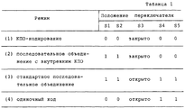
На фиг. 3 показана структурная схема гибкого программируемого кодера, который осуществляет все четыре перечисленных режима кодирования. Как видно, гибкий программируемый кодер содержит кодер 100 для кодирования с параллельным объединением, кодер 102 для внешнего кодирования, а также пять переключателей S1-S5. Кодер 100 для кодирования с параллельным объединением содержит N кодеров, N-1 перемежителей, а также формирователь кодовых слов 106. В приведенной далее табл.1 показаны положения переключателей для различных режимов кодирования. In FIG. 3 shows a block diagram of a flexible programmable encoder that implements all four of the encoding modes listed. As can be seen, the flexible programmable encoder comprises an
На фиг.4 приведена структурная схема гибкого программируемого декодера, обеспечивающего декодирование для четырех приведенных выше режимов кодирования. Данный программируемый составной декодер содержит декодер 110 для снятия кодов с параллельным объединением, пороговое решающее устройство 112 для реализации решающего правила, декодер 114 для снятия внешнего кода, а также шесть переключателей S1-S6. Полагая, что выходной сигнал декодера 110 представляет собой вероятность того, что значение декодированных битов равняется нулю, примерное решающее правило имеет следующий вид: если выходной сигнал больше 1/2, то принимается решение о том, что декодированный бит равен нулю; если меньше 1/2, то принимается нулевое значение; если равняется 1/2, то принимается произвольное значение. Figure 4 shows the structural diagram of a flexible programmable decoder that provides decoding for the four above encoding modes. This programmable composite decoder comprises a
Декодер 110 для снятия кодов с параллельным объединением далее содержит преобразователь составного кодового слова в составные части кодового слова 116, N декодеров составных частей, N-1 перемежителей и два одинаковых деперемежителя 118. Каждый деперемежитель выполняет функцию восстановления порядка, в результате чего восстанавливается последовательность элементов информации, которая была изменена N-1 перемежителями, подключены последовательно в их исходном порядке. В приведенной далее табл.2 обобщены положения переключателей для различных режимов декодирования. (В таблице "X" обозначает ситуацию "не важно", т.е. когда переключатель может находиться в любом положении). The
В ТОМА используются различные коды (например, КПО-кодирование, КПО-кодирование с добавлением битов в конец, рекурсивное систематическое сверточное, нерекурсивное систематическое сверточное, блочное кодирование) в различных сочетаниях (например, режимы 1, 2, 3 и 4) в зависимости от связного приложения и требуемой скорости передачи. TOMA uses different codes (for example, KPO coding, KPO coding with bits added to the end, recursive systematic convolutional, non-recursive systematic convolutional, block coding) in various combinations (for example,
Когда в любом из описанных выше режимов используется сверточный код, программируемый кодер на фиг.3 может выполнять также операцию перфорирования кода по известному закону для увеличения скорости результирующего кода, а программируемый декодер на фиг.4 может выполнять также операцию деперфорирования. Если в качестве составной кода при кодировании с параллельным объединением используются перфорированные сверточные коды, то формирователь кодового слова на фиг.3 удаляет информационные биты из составляющих кодовых слов в соответствии с требуемым законом перфорирования. В этом случае преобразователь составного кодового слова в составляющие кодовые слова, входящий в состав КПО-декодера, вставляет нейтральные значения для перфорированных битов в составляющих словах, которые выдаются на декодеры составляющих слов. Заметим, что в режимах 3 или 4 переключатели кодера S4 и S5, а также переключатели декодера S1 и S2 установлены в положение 0. Следовательно, на фиг.3 и фиг. 4 показано, что когда перфорированные сверточные коды используются в режимах 3 или 4, то устройства перфорирования 140 и деперфорирования 142 не выполняют операции перфорирования и деперфорирования кода соответственно. When a convolutional code is used in any of the modes described above, the programmable encoder of FIG. 3 can also perform the punching operation of the code according to the known law to increase the speed of the resulting code, and the programmable decoder of FIG. 4 can also perform the deperforation operation. If perforated convolutional codes are used as the composite code in parallel combining, then the codeword generator in FIG. 3 removes information bits from the constituent codewords in accordance with the required perforation law. In this case, the converter of the composite code word into constituent code words included in the KPO decoder inserts neutral values for the perforated bits in the constituent words that are output to the decoders of the constituent words. Note that in modes 3 or 4, the encoder switches S4 and S5, as well as the switches of the decoder S1 and S2 are set to 0. Therefore, in FIG. 3 and FIG. 4 shows that when perforated convolutional codes are used in modes 3 or 4, the punching and 140 punching devices 142 do not perform punching and code punching operations, respectively.
В предпочтительном варианте воплощения изобретения сверточные коды используются в качестве составляющих кодов во внутреннем коде с параллельным объединением, а блоковые коды (например, код Рида-Соломона или БЧХ-код) используется в качестве внешнего кода с последовательным объединением. In a preferred embodiment, convolutional codes are used as constituent codes in the parallel-coded internal code, and block codes (e.g., Reed-Solomon code or BCH code) are used as the serial-coded external code.
В предпочтительном варианте, в котором ТОМА передаются сигналы с расширенным спектром, в сочетании с множественным доступом с кодовым разделением используется протокол произвольного доступа к каналам типа ALOHA. В приемнике центрального терминала используется несколько демодуляторов для каждого расширяющего кода с целью приема перекрывающихся во времени сигналов, в которых используется одна и та же расширяющая последовательность, но с различными задержками во времени. Каждый демодулятор для заданной расширяющей последовательности демодулирует сигнал, используя различный временной сдвиг этой расширяющей последовательности. In a preferred embodiment in which TOMA spread spectrum signals are transmitted, a random access protocol for ALOHA channels is used in combination with code division multiple access. A central terminal receiver uses several demodulators for each spreading code to receive time-overlapping signals that use the same spreading sequence, but with different time delays. Each demodulator for a given spreading sequence demodulates the signal using a different time offset of this spreading sequence.
Кроме того, в предпочтительном варианте выполнения изобретения одна или несколько расширяющих последовательностей зарезервированы для использования в ТОМА на протяжении определенных периодов времени на выделенной основе для создания высококачественных каналов с более высокой пропускной способностью. Запросы на резервирование от ТОМА и назначения обрабатываются сетевым контроллером, подключенным к центральному терминалу. In addition, in a preferred embodiment of the invention, one or more spreading sequences are reserved for use in TOMA for certain periods of time on a dedicated basis to create high-quality channels with higher throughput. Reservation requests from TOMA and destination are processed by a network controller connected to the central terminal.
В предпочтительном варианте при использовании сигналов с расширенным спектром и описанных выше программируемых кодера и декодера система связывает заданную расширяющую последовательность с конкретным корректирующим ошибки кодом, что позволяет различным сигналам одновременно использовать различные коды, исправляющие ошибки. Так как каждая обнаруженная расширяющая последовательность сигнала идентифицируется соответствующим демодулятором, приемник может соответствующим образом устанавливать конфигурацию программируемого декодера для каждого обнаруженного сигнала. Этот режим функционирования сети применим для одновременной поддержки нескольких приложений, имеющих различные требования к корректирующей способности кодов, и при этом нет необходимости в дополнительной управляющей сигнализации. In a preferred embodiment, when using spread-spectrum signals and the programmable encoder and decoder described above, the system associates a given spreading sequence with a specific error-correcting code, which allows different signals to simultaneously use different error-correcting codes. Since each detected spreading sequence of a signal is identified by a corresponding demodulator, the receiver can appropriately set the configuration of a programmable decoder for each detected signal. This mode of network operation is applicable for simultaneous support of several applications that have different requirements for the correcting ability of codes, and there is no need for additional control signaling.
Циркулярный МАВ декодер с максимальной апостериорной вероятностью, который может использоваться в качестве составляющих декодеров на фиг.4, раскрыт в совместно заявляемой и присоединенной по ссылке заявке на американский патент No.08/636742. Циркулярный МАВ-декодер позволяет получать как оценку кодированного блока данных, так и надежную информацию для получателя данных, являясь, например, сигнальным процессором восстановления речи для использования при скрытии ошибки передачи или протокольным процессором для пакетированных данных, в качестве средства измерения вероятности блоковой ошибки для использования в случае решений с повторным запросом. Как описано в совместно рассматриваемой, присоединяемой заявке на американский патент No.08/636732 авторов Stephen M. Hladik и John B.Anderson, поданной 19 апреля 1996 г. и присоединенной по ссылке, циркулярный МАВ-декодер может использоваться для декодирования сверточных кодов с добавлением битов в конец, в частности, когда эти коды используются в качестве составляющих кодов в схеме кодирования с параллельным объединением. A circular MAV decoder with maximum posterior probability, which can be used as component decoders in FIG. 4, is disclosed in U.S. Patent Application No. 08/636742, jointly claimed and incorporated by reference. The circular MAV decoder allows one to obtain both an estimate of the encoded data block and reliable information for the data recipient, being, for example, a speech recovery signal processor for use in concealing transmission errors or a protocol processor for packet data as a means of measuring the probability of a block error for use in the case of re-query solutions. As described in co-pending, adjoining U.S. Patent Application No. 08/636732 by Stephen M. Hladik and John B. Anderson, filed April 19, 1996 and linked by reference, a circular MAV decoder can be used to decode convolutional codes with the addition of bits to the end, in particular when these codes are used as constituent codes in a parallel combining coding scheme.
Циркулярный МАВ-декодер для исправляющих ошибки решетчатых кодов, в котором применяется добавление битов в конец в соответствии с заявкой на американский патент No. 08/636742, позволяет получить выходной сигнал в соответствии с мягким решающим правилом. Циркулярный МАВ-декодер обеспечивает оценку вероятностей состояний в первом состоянии решетки, причем эти вероятности замещают априорно известные начальные состояния в обычном МАВ-декодере. Циркулярный МАВ-декодер получает распределение начальных вероятностей одним из двух способов. Первый способ включает в себя решение задачи собственных значений, для которых результирующий собственный вектор представляет собой требуемое распределение вероятностей начальных состояний; получив информацию о начальных состояниях циркулярный МАВ-декодер выполняет оставшуюся часть процедуры декодирования в соответствии с обычным алгоритмом МАВ-декодирования. Второй способ основан на рекурсии, в которой итерации сходятся к распределению начальных состояний. После подходящего числа итераций состояние на циркулярной последовательности состояний становится известным с высокой вероятностью и циркулярный МАВ-декодер выполняет оставшуюся часть декодирования в соответствии с обычным алгоритмом МАВ-декодирования, описанным в статье "Оптимальное декодирование линейных кодов с целью минимизации частоты появления ошибок", Balh, Cocke, Jelinek и Raviv, IEEE Transactions on Information Theory, c. 284-287. Март 1974. A circular MAV decoder for error-correcting trellis codes, which uses the addition of bits to the end in accordance with U.S. Patent Application No. 08/636742, allows you to get the output signal in accordance with the soft decision rule. The circular MAV decoder provides an estimate of the probabilities of states in the first state of the lattice, and these probabilities replace the a priori known initial states in a conventional MAV decoder. The circular MAV decoder receives the initial probability distribution in one of two ways. The first method involves solving the eigenvalue problem for which the resulting eigenvector represents the required probability distribution of the initial states; Having received information on the initial states, the circular MAV decoder performs the remainder of the decoding procedure in accordance with the conventional MAV decoding algorithm. The second method is based on recursion, in which iterations converge to the distribution of the initial states. After a suitable number of iterations, the state on the circular sequence of states becomes known with high probability and the circular MAV decoder performs the rest of the decoding in accordance with the usual MAV decoding algorithm described in the article “Optimal decoding of linear codes to minimize the error rate”, Balh, Cocke, Jelinek and Raviv, IEEE Transactions on Information Theory, c. 284-287. March 1974.
Цель обычного алгоритма МАВ-декодирования заключается в отыскании условных вероятностей:
Р [состояние m в момент t|вых. сигналы приемных каналов y1...yL].The purpose of the conventional MAV decoding algorithm is to find conditional probabilities:
P [state m at time t | out. signals of the receiving channels y 1 ... y L ].
Величина L в приведенном выражении обозначает длину блока данных, измеряемую числом декодированных символов. (Кодер для (n, k)-кода при поступлении на его вход k битов формирует на выходе n битов). Обозначение yt использовано для выходного сигнала (символа) канала в момент времени t.The value L in the above expression denotes the length of the data block, measured by the number of decoded symbols. (The encoder for the (n, k) -code when it arrives at its input k bits generates n bits at the output). The designation y t is used for the output signal (symbol) of the channel at time t.
Алгоритм МАВ-декодирования в первую очередь в действительности отыскивает вероятности:
λt(m) = P[St = m; Y
при этом получаются совместные вероятности того, что в момент t состояние кодера St есть m, а выходные сигналы приемных каналов Y1 L= [y1,..yL]. Полученные вероятности являются искомыми вероятностями, умноженными на некоторые константы (P[Y1 L] вероятности того, что набор сигналов на выходе приемных каналов будет равен [y1,...yL]).The MAV decoding algorithm first of all actually searches for probabilities:
λ t (m) = P [S t = m; Y
this gives the joint probabilities that at time t the state of the encoder S t is m, and the output signals of the receiving channels Y 1 L = [y 1 , .. y L ]. The obtained probabilities are the sought probabilities multiplied by some constants (P [Y 1 L ] is the probability that the set of signals at the output of the receiving channels will be [y 1 , ... y L ]).
Определим элементы матрицы Гt следующим образом: Гt(i,j)=Р [состояние j в момент t; Yt| состояние i в момент t-1].We define the elements of the matrix Г t as follows: Г t (i, j) = Р [state j at time t; Y t | state i at time t-1].
Матрица Гt вычисляется как функция вероятности канального перехода R(Yt, X), вероятность pt(m|m′) того, что кодер осуществляет переход из состояний m' в m в момент времени t, и вероятность qt(x|m′m) того, что выходной символ кодера является X, причем предыдущее состояние кодера m', а текущее состояние кодера - m. В частности, каждый элемент Гt вычисляется путем суммирования по всем возможным выходам кодера Х следующим образом:
![]()
МАВ-декодер вычисляет L таких матриц, по одной для каждого состояния решетки. Они получаются из символов на выходе приемных каналов и с учетом характера ветвей решетки для заданного кода.The matrix Г t is calculated as a function of the probability of the channel transition R (Y t , X), the probability p t (m | m ′) of the encoder transitioning from the states m 'to m at time t, and the probability q t (x | m′m) that the output symbol of the encoder is X, with the previous state of the encoder m 'and the current state of the encoder m. In particular, each element Г t is calculated by summing over all possible outputs of the encoder X as follows:
![]()
The MAV decoder calculates L such matrices, one for each lattice state. They are obtained from the symbols at the output of the receiving channels and taking into account the nature of the lattice branches for a given code.
Далее определяются М элементов совместной вероятности вектора-строки αt:
![]()
и М элементов условной вероятности вектора-столбцаβt
![]()
для j= 0,1,...,(М-1), где М - число состояний кодера (заметим, что матрицы и векторы выделяются полужирным наклонным шрифтом).Next, M elements of the joint probability of the row vector α t are determined:
![]()
and M elements of conditional probability of the column vector β t
![]()
for j = 0,1, ..., (M-1), where M is the number of encoder states (note that matrices and vectors are highlighted in bold oblique).
Этапы алгоритма МАВ-декодирования заключаются в следующем:
(i) вычисляются α1,...,αL при помощи прямой рекурсии:
αt = αt-1 Гt, t = 1,..., L, (5)
(ii) вычисляются β1,...βL-1 при помощи обратной рекурсии:
βt = Гt+1 βt+1, t = L-1,..., 1 (6)
(iii) вычисляются элементы λt:
λt(i) = αt(i) βt(i), для всех i, t=1,...,L. (7)
(iv) при необходимости отыскиваются связанные величины. Например, пусть Аt j - набор состояний St=[St 1, St 2,...,St km], таких, что j-й элемент St, St j равен нулю. Для обычного нерекурсивного решетчатого кода St j=dt j, j-му информационному биту в момент t. Следовательно, на выходе декодера с мягким решающим правилом имеем:
![]()
где ![]()
(i) α 1 , ..., α L are calculated using direct recursion:
α t = α t-1 Г t , t = 1, ..., L, (5)
(ii) β 1 , ... β L-1 are computed using inverse recursion:
β t = Г t + 1 β t + 1 , t = L-1, ..., 1 (6)
(iii) the elements λ t are calculated:
λ t (i) = α t (i) β t (i), for all i, t = 1, ..., L. (7)
(iv) if necessary, related quantities are found. For example, let A t j be the set of states S t = [S t 1 , S t 2 , ..., S t km ] such that the jth element S t , S t j is equal to zero. For a regular non-recursive trellis code, S t j = d t j , the jth information bit at time t. Therefore, at the output of the decoder with a soft decision rule, we have:
![]()
Where ![]()
Жесткое решающее правило декодера или выходной декодированный бит получают путем приложения P[d

При этом, если P[d
Moreover, if P [d
В качестве другого примера связанных величин для вышеупомянутого этапа (iv) вычисляется матрица вероятностей σt со следующими элементами:

Эти вероятности могут быть использованы, когда требуется определить апостериорную вероятность выходных битов кодера. Эти вероятности используются также при декодировании рекурсивных сверточных кодов.As another example of related quantities for the aforementioned step (iv), a probability matrix σ t is calculated with the following elements:
These probabilities can be used when it is necessary to determine the posterior probability of the output bits of the encoder. These probabilities are also used in decoding recursive convolutional codes.
В стандартном применении алгоритма МАВ-декодирования прямая рекурсия начинается с вектора α0 = (1,0,..., 0), а обратная рекурсия начинается с вектора βL = (1,0,..., 0)T. Эти начальные условия основаны на предположениях, что начальное состояние кодера S0=0 и конечное состояние кодера SL=0.In the standard application of the MAV decoding algorithm, direct recursion begins with the vector α 0 = (1,0, ..., 0), and reverse recursion begins with the vector β L = (1,0, ..., 0) T. These initial conditions are based on the assumption that the initial state of the encoder is S 0 = 0 and the final state of the encoder is S L = 0.
В одном из вариантов реализации циркулярного МАВ-декодера распределение вероятностей начальных состояний определяется путем решения задачи собственных значений следующим образом. Пусть αt, βt, Гt и λt остаются теми же, что и прежде, а α0 и βL определяются следующим образом:
положим βL равным вектору-столбцу (111...1)T
Пусть α0 является неизвестной (векторной) переменной.In one embodiment of the implementation of a circular MAV decoder, the probability distribution of the initial states is determined by solving the eigenvalue problem as follows. Let α t , β t , Г t and λ t remain the same as before, and α 0 and β L are defined as follows:
put β L equal to the column vector (111 ... 1) T
Let α 0 be an unknown (vector) variable.
Тогда:
(i) вычисляют Гt для t=1,2,...,L в соответствии с выражением (2).Then:
(i) calculate Г t for t = 1,2, ..., L in accordance with the expression (2).
(ii) находят наибольшее собственное число матричного произведения Г1Г2.. . ГL. Нормируют соответствующий собственный вектор так, чтобы сумма его компонентов оказалась равной единице. Этот вектор представляет собой решение α0. Собственное значение является Р[Y1 L].(ii) find the largest eigenvalue of the matrix product Γ 1 Γ 2 ... G L. The corresponding eigenvector is normalized so that the sum of its components is equal to unity. This vector is a solution of α 0 . The eigenvalue is P [Y 1 L ].
(iii) при помощи выражения (5) с прямой рекурсией находят последовательные векторы αt.
(iv) начиная с βL, начальное значение которому присвоено так, как это описано выше, получают βt путем обратной рекурсии в соответствии с выражением (6).(iii) using expression (5) with direct recursion find successive vectors α t .
(iv) starting with β L , the initial value of which is assigned as described above, receive β t by reverse recursion in accordance with expression (6).
(v) в соответствии с (7) получают λt, а затем и другие необходимые переменные, как, например, выходные значения с мягким решающим правилом P[d
Неизвестная переменная α0 удовлетворяет матричному уравнению:

Учитывая, что приведенная формула отражает соотношения между вероятностями, произведение матриц Гt в правой части имеет наибольшее собственное значение, равное Р [Y1 L], и соответствующий собственный вектор должен быть вектором вероятностей.(v) in accordance with (7), they obtain λ t , and then other necessary variables, such as, for example, output values with a soft decision rule P [d
The unknown variable α 0 satisfies the matrix equation:
Given that the above formula reflects the relationship between the probabilities, the product of the matrices t t on the right-hand side has the largest eigenvalue equal to P [Y 1 L ], and the corresponding eigenvector should be a probability vector.
При начальном βL = (111...1)T выражение (6) позволяет получить βL-1. Таким образом, повторное применение этой обратной рекурсии позволяет получить все βt. После того, как α0 известен и βL установлен, все вычисления в циркулярном МАВ-декодере соответствуют обычному алгоритму МАВ-декодирования.With the initial β L = (111 ... 1) T, expression (6) allows one to obtain β L-1 . Thus, reapplying this inverse recursion allows you to get all β t . After α 0 is known and β L is set, all calculations in the circular MAV decoder correspond to the usual MAV decoding algorithm.
В альтернативном варианте реализации циркулярного МАВ-декодера распределение вероятностей состояний определяется с использованием рекурсивного способа. В частности, в одном варианте реализации (метод динамической сходимости) рекурсивная процедура продолжается до тех пор, пока не будет выявлена сходимость декодера. В этой рекурсии (или в методе динамической сходимости) этапы (i) и (ii) описанного выше способа, основанного на вычислении собственного вектора, замещаются следующими этапами:
(ii. a) начиная с начального значения α0, равного (1/М,...,1/М), где М - число состояний решетки, прямой рекурсией осуществляются вычисления L раз. Нормируют результат так, чтобы сумма элементов каждого нового αt равнялась единице. Сохраняют все L векторов αt.
(ii.b) пусть α0 равняется αl из предыдущего этапа и, начиная с t=1 как и прежде вычисляется первое Lw-min векторов вероятности αt.
После этого вычисляют ![]()
для m= 0,1, ..., М-1, и t=l,2,..., Lw-min где Lw-min - минимальное приемлемое число ступеней решетки. Нормируют прежним способом. Сохраняют только самый последний набор L векторов α, найденных в соответствии с рекурсивной процедурой на этапах (ii. a) и (ii.b), а также ![]()
(ii. a) starting from the initial value of α 0 equal to (1 / M, ..., 1 / M), where M is the number of states of the lattice, L times are calculated by direct recursion. The result is normalized so that the sum of the elements of each new α t is equal to unity. Save all L vectors α t .
(ii.b) let α 0 be equal to α l from the previous stage and, starting from t = 1, the first L w-min probability vectors α t are calculated as before.
After that calculate ![]()
for m = 0,1, ..., M-1, and t = l, 2, ..., L w-min where L w-min is the minimum acceptable number of lattice steps. Normalize in the same way. Only the most recent set of L vectors α found in accordance with the recursive procedure in steps (ii.a) and (ii.b), as well as ![]()
(ii.c) сравнивают ![]()
![]()
![]()
![]()
(ii. d) пусть t=t+1 и вычисляется αt = αt-1 Гt. Нормируют прежним способом. Сохраняют только набор самых последних L вычисленных векторов α и αt, ранее найденный на этапе (ii.a).(ii. d) let t = t + 1 and calculate α t = α t-1 Г t . Normalize in the same way. Only the set of the most recent L calculated vectors α and α t , previously found in step (ii.a), is retained.
(ii. e) сравнивают новые αt с ранее полученным набором. Если М новых и старых αt находятся в пределах допустимого интервала, то выполнить этап (iv). В противном случае перейти к этапу (ii.d), если два последних вектора не попадают в допустимый интервал и если число рекурсий не превышает определенного максимального значения (обычно 2L); перейти к этапу (iv) в противном случае.(ii. e) compare the new α t with the previously obtained set. If M new and old α t are within the acceptable interval, then perform step (iv). Otherwise, go to step (ii.d) if the last two vectors do not fall into the allowable interval and if the number of recursions does not exceed a certain maximum value (usually 2L); go to step (iv) otherwise.
После этого способ продолжается на этапах (iv) и (v), описанных выше при раскрытии способа, основанного на вычислении собственного вектора, для получения выходных сигналов в соответствии с мягким решающим правилом и выходных декодированных битов с циркулярного МАВ-декодера. After that, the method continues to steps (iv) and (v) described above in the disclosure of the method based on the calculation of the eigenvector to obtain the output signals in accordance with the soft decision rule and the output decoded bits from the circular MAV decoder.
В другом альтернативном варианте реализации циркулярного МАВ-декодера, описанного в заявке на американский патент No.08/636742, рекурсивная процедура модифицируется таким образом, что декодеру нужно обработать только заранее заданное, фиксированное число ступеней решетки во вторую очередь, то есть на заданную глубину перекрытия. Это обеспечивает преимущества при реализации, обусловленные тем, что объем вычислений, необходимый для декодирования, остается прежним для каждого кодированного блока сообщения. Соответственно сокращается сложность программного и аппаратного обеспечения. In another alternative embodiment of the circular MAV decoder described in U.S. Patent Application No. 08/636742, the recursive procedure is modified so that the decoder only needs to process a predetermined, fixed number of lattice steps in the second place, i.e., at a given overlap depth . This provides implementation advantages due to the fact that the amount of computation required for decoding remains the same for each coded message block. Accordingly, the complexity of software and hardware is reduced.
Одним из способов определения требуемой глубины перекрытия для МАВ-декодирования сверточного кода с добавлением битов в конец заключается в определении ее путем экспериментирования с программным или аппаратным обеспечением, причем для этого требуется циркулярный МАВ-декодер с переменной глубиной перекрытия и экспериментальные исследования проводятся с целью измерения частоты поступления ошибок в зависимости от Еb/Nо при допустимом увеличении глубины перекрытия. Вычисляется минимальная глубина перекрытия декодера, которая обеспечивает минимальную вероятность ошибки декодированных битов для определенного отношения Eb/No, при которой дальнейшее увеличение глубины перекрытия не приводит к снижению вероятности ошибки.One way to determine the required overlap depth for MAV decoding of a convolutional code with the addition of bits at the end is to determine it by experimenting with software or hardware, and this requires a circular MAV decoder with a variable depth of overlap and experimental studies are conducted to measure the frequency the occurrence of errors depending on E b / Nо with a permissible increase in the depth of overlap. The minimum decoder overlap depth is calculated, which provides the minimum error probability of decoded bits for a specific E b / No ratio, at which a further increase in the overlap depth does not reduce the probability of error.
Если скорость поступления ошибочных декодированных битов, превышающая минимально достижимую для заданного отношения Eb/No, является допустимой, то представляется возможным сократить требуемое число ступеней решетки, обрабатываемых циркулярным МАВ-декодером. В частности, описанная выше процедура отыскания глубины перекрытия может быть просто прекращена при достижении требуемой средней вероятности ошибки.If the arrival rate of erroneous decoded bits, exceeding the minimum achievable for a given ratio E b / No, is acceptable, it seems possible to reduce the required number of lattice steps processed by a circular MAV decoder. In particular, the above-described procedure for finding the depth of overlap can simply be stopped when the desired average probability of error is reached.
Другой способ определения глубины перекрытия для заданного кода основан на использовании свойств кодового расстояния. Для этого необходимо определить две различных решающих глубины декодера (decoder decision depth). В данном случае термин "правильный путь" означает последовательность состояний или путь сквозь решетку, которые получаются в результате кодирования блока информационных битов. Термин "некорректное подмножество узла" означает набор всех неправильных ветвлений (решетки), уходящих с правильного пути узла и его наследников. Обе определенные выше решающие глубины зависят от сверточного кодера. Another way to determine the depth of overlap for a given code is based on the use of code distance properties. To do this, you need to define two different decoder decision depths. In this case, the term “correct path” means a sequence of states or a path through a lattice that results from encoding a block of information bits. The term “incorrect subset of a node” means a set of all incorrect branches (lattices) that leave the correct path of the node and its descendants. Both decisive depths defined above are dependent on the convolutional encoder.
Решающие глубины определяются следующим образом:
(i) определяют, что передняя решающая глубина для корректировки е ошибок, LF(е), есть первая глубина в решетке, при которой все пути некорректного подмножества начального узла правильного пути, независимо от того, сливаются ли они в дальнейшем с правильным путем или нет, отстоят от правильного пути на расстояние, превышающее расстояние Хемминга 2е. Значение LF(e) состоит в том, что если число ошибок перед начальным узлом не превышает е и известное кодирование начинается с этого момента, то декодер должен снимать код безошибочно. Формальное представление в табличном виде передней решающей глубины для сверточных кодов было получено J.B. Anderson и K. Balachandran в статье "Решающие глубины для сверточных кодов", IEEE Transactions on Information Theory, v. IT-35, c.455-459, март 1989. Некоторые свойства LF(e) описаны в этой статье и также в книге J.B.Anderson и S.Mohan "Кодирование источника и канала - алгоритмический подход", Kluwer Academic Piblishers, Norwell, MA, 1991. Основное из этих свойств заключается в том, что между LF и е существует простое линейное соотношение; например, для кодов 1/2 LF приблизительно равно 9.08е.Decisive depths are defined as follows:
(i) determine that the forward decisive depth for correcting e errors, LF (e), is the first depth in the lattice at which all paths of an incorrect subset of the starting node of the correct path, regardless of whether they merge with the correct path in the future are separated from the correct path by a distance exceeding the Hamming distance 2e. The value of LF (e) is that if the number of errors in front of the initial node does not exceed e and the known encoding starts from this moment, then the decoder must correctly read the code. A formal tabular presentation of the front decimal depth for convolutional codes was obtained by JB Anderson and K. Balachandran in the article Decisive Depths for Convolutional Codes, IEEE Transactions on Information Theory, v. IT-35, c.455-459, March 1989. Some of the properties of LF (e) are described in this article and also in JBAnderson and S. Mohan's book “Source and Channel Coding - An Algorithmic Approach”, Kluwer Academic Piblishers, Norwell, MA, 1991. The main of these properties is that there is a simple linear relationship between LF and e; for example, for 1/2 LF codes, approximately 9.08e.
(ii) далее определяют, что не объединяющая решающая глубина для исправления е ошибок, LU (е), есть первая глубина в решетке, при которой все пути в решетке, которые никогда не соприкасаются с правильным путем, отстоят от правильного пути на расстояние, превышающее расстояние Хемминга 2е. (ii) it is further determined that the non-decisive decisive depth for correcting e errors, LU (e), is the first depth in the lattice at which all paths in the lattice that never touch the correct path are separated from the correct path by a distance exceeding Hamming distance 2e.
Значение LU (е) для циркулярного МАВ-декодирования с мягким решающим правилом состоит в том, что вероятность идентификации состояния на действительном передаваемом пути является наивысшей после того, как декодер обработает LU (е) ступеней решетки. Следовательно, минимальная глубина перекрытия для циркулярного МАВ-декодера составляет LU(e). Вычисления глубины LU(e) показывают, что она всегда больше, чем LF(e), но что она подчиняется тому же аппроксимирующему закону. Это означает, что если необъединяющая решающая глубина кода не известна, то минимальная глубина перекрытия должна быть выбрана равной передней решающей глубине LF(e). The value of LU (e) for circular MAV decoding with a soft decision rule is that the probability of identifying the state on the actual transmitted path is the highest after the decoder processes the LU (e) of the grating stages. Therefore, the minimum overlap depth for a circular MAV decoder is LU (e). Calculations of the depth LU (e) show that it is always greater than LF (e), but that it obeys the same approximating law. This means that if the non-combining decision depth of the code is not known, then the minimum overlap depth should be chosen equal to the front decision depth LF (e).
Отыскивая минимальную необъединяющую решающую глубину для заданного кодера мы находим наименьшее число ступеней решетки, которое должно быть обработано конкретным циркулярным декодером, формирующим выходные сигналы на основе мягкого решающего правила. Алгоритм отыскания LF(e), передней решающей глубины, был предложен J.B.Anderson и K. Balachandran в упоминавшейся выше статье "Решающие глубины для сверточных кодов". Для отыскания LU(e):
(i) вытягивают кодовые решетки слева направо, начиная одновременно со всех узлов решетки, исключая узлы для нулевого состояния.Finding the minimum non-combining decisive depth for a given encoder, we find the smallest number of lattice steps that should be processed by a particular circular decoder that generates output signals based on a soft decision rule. The algorithm for finding LF (e), the front decisive depth, was proposed by JBAnderson and K. Balachandran in the deciding depth for convolutional codes article mentioned above. To find LU (e):
(i) extend the code gratings from left to right, starting simultaneously from all nodes of the grating, excluding nodes for the zero state.
(ii) на каждом уровне удаляют все пути, которые сливаются с правильным (полностью нулевым) путем; не вытягивают пути, выходящие из правильного (нулевого) узла состояния. (ii) at each level, remove all paths that merge with the correct (completely zero) path; Do not stretch paths exiting the correct (zero) state node.
(iii) на уровне k среди путей, оканчивающихся в узлах на этом уровне, находят наименьшее расстояние Хемминга или вес. (iii) at level k, among the paths ending in nodes at that level, find the smallest Hamming distance or weight.
(iv) если это наименьшее расстояние превышает 2е, то происходит прекращение вычислений. Это означает, что LU(e)=k. (iv) if this smallest distance exceeds 2e, then the computation ceases. This means that LU (e) = k.
Как описано в заявке на американский патент No. 08/636742, экспериментирование путем компьютерного моделирования привело к двум неожиданным результатам: (1) обработка с перекрытием βt улучшает характеристики декодера; (2) использование глубины перекрытия LU(e)+LF(e)≈(2LF(e) значительно улучшает характеристики. Следовательно, предпочтительный вариант реализации алгоритма циркулярного МАВ-декодера основан на рекурсии, включающей следующие этапы:
(i) вычисляют Гt для t=1, 2,...,L в соответствии с выражением (2).As described in U.S. Patent Application No. 08/636742, experimentation by computer simulation led to two unexpected results: (1) processing with overlapping β t improves decoder performance; (2) using the overlap depth LU (e) + LF (e) ≈ (2LF (e) significantly improves the performance. Therefore, the preferred embodiment of the circular MAV decoder algorithm is based on recursion, which includes the following steps:
(i) compute Г t for t = 1, 2, ..., L in accordance with expression (2).
(ii) начиная с начального значения α0, равного (1/М,..., 1/М), где М - число состояний в решетке, осуществляют вычисление по прямой рекурсии в соответствии с выражением (5) (L+LW) раз для u=1, 2,... (L+Lw), где L - глубина перекрытия декодера. Индекс уровня решетки t принимает значения (u-1) mod L) + 1. После того, как декодер "прогоняет" (wraps around) последовательность символов, принимаемых в канале, αt трактуется как α0. Нормализуют результат таким образом, что сумма элементов каждого нового вектора αt равна единице. Оставляют L последних векторов α, полученных в результате этой рекурсии.(ii) starting from the initial value of α 0 equal to (1 / M, ..., 1 / M), where M is the number of states in the lattice, direct recursion is calculated in accordance with expression (5) (L + L W ) times for u = 1, 2, ... (L + L w ), where L is the depth of the decoder overlap. The lattice level index t takes the values (u-1) mod L) + 1. After the decoder “wraps around” the sequence of characters received in the channel, α t is treated as α 0 . Normalize the result so that the sum of the elements of each new vector α t is equal to one. Leave L of the last vectors α obtained as a result of this recursion.
(iii) начиная с начального значения βt, равного (1,...1)T, в соответствии с выражением обратной рекурсии (6) осуществляют вычисления (L+Lw) раз для u=1,2,... (L+Lw). Индекс уровня решетки принимает значения L-(u mod L). После того, как декодер "прогоняет" принятую последовательность, β1 используется как βL+1,, а Г1- используется как ГL+1 при вычислении нового βL. Нормируют результат таким образом, что сумма элементов каждого нового βt равняется единице. Как и прежде, сохраняют L последних векторов β, полученных в результате этой рекурсии.(iii) starting from the initial value of β t equal to (1, ... 1) T , in accordance with the inverse recursion expression (6), calculations are performed (L + L w ) times for u = 1,2, ... ( L + L w ). The lattice level index takes the values L- (u mod L). After the decoder “runs through” the received sequence, β 1 is used as β L + 1 , and Г 1 is used as Г L + 1 when calculating the new β L. The result is normalized in such a way that the sum of the elements of each new β t is equal to one. As before, retain the L last vectors β obtained as a result of this recursion.
Следующий этап данного рекурсивного способа совпадает с этапом (v) приведенного выше способа, основанного на вычислении собственного вектора и заключающегося в получении выходных мягких решений и декодированных битов при помощи циркулярного МАВ-декодера. The next step of this recursive method coincides with step (v) of the above method, based on the calculation of the eigenvector and consisting in obtaining output soft solutions and decoded bits using a circular MAV decoder.
Несмотря на то, что выше были приведены предпочтительные варианты реализации настоящего изобретения, ясно, что эти варианты реализации приведены исключительно в качестве примеров. Многочисленные вариации, изменения и замены могут быть предложены без выхода за пределы объема изобретения. Соответственно подразумевается, что изобретение ограничивается только основной идеей и объемом, раскрытыми в нижеследующей формуле. Although the preferred embodiments of the present invention have been described above, it is clear that these embodiments are provided solely as examples. Numerous variations, changes, and substitutions may be proposed without departing from the scope of the invention. Accordingly, it is understood that the invention is limited only by the basic idea and scope disclosed in the following claims.
Claims (12)
Applications Claiming Priority (2)
| Application Number | Priority Date | Filing Date | Title |
|---|---|---|---|
| US08/684,276 | 1996-07-17 | ||
| US08/684,276 US5734962A (en) | 1996-07-17 | 1996-07-17 | Satellite communications system utilizing parallel concatenated coding |
Publications (2)
| Publication Number | Publication Date |
|---|---|
| RU97112743A RU97112743A (en) | 1999-06-27 |
| RU2191471C2 true RU2191471C2 (en) | 2002-10-20 |
Family
ID=24747407
Family Applications (1)
| Application Number | Title | Priority Date | Filing Date |
|---|---|---|---|
| RU97112743/09A RU2191471C2 (en) | 1996-07-17 | 1997-07-16 | Satellite communication system using encoding with parallel integration |
Country Status (21)
| Country | Link |
|---|---|
| US (1) | US5734962A (en) |
| EP (1) | EP0820159B1 (en) |
| JP (1) | JP3833783B2 (en) |
| KR (1) | KR100496232B1 (en) |
| CN (1) | CN1113486C (en) |
| AR (1) | AR008403A1 (en) |
| AU (1) | AU718266B2 (en) |
| BR (1) | BR9704012A (en) |
| CA (1) | CA2208413C (en) |
| CZ (1) | CZ290425B6 (en) |
| DE (1) | DE69735979T2 (en) |
| ES (1) | ES2264153T3 (en) |
| HU (1) | HUP9701215A3 (en) |
| ID (1) | ID17541A (en) |
| IL (1) | IL121232A (en) |
| MX (1) | MX9705401A (en) |
| NO (1) | NO320121B1 (en) |
| PL (1) | PL184615B1 (en) |
| RU (1) | RU2191471C2 (en) |
| UA (1) | UA44752C2 (en) |
| ZA (1) | ZA975952B (en) |
Cited By (4)
| Publication number | Priority date | Publication date | Assignee | Title |
|---|---|---|---|---|
| US8451770B2 (en) | 2002-05-06 | 2013-05-28 | Qualcomm Incorporated | Multi-media broadcast and multicast service (MBMS) in a wireless communication system |
| US8694869B2 (en) | 2003-08-21 | 2014-04-08 | QUALCIMM Incorporated | Methods for forward error correction coding above a radio link control layer and related apparatus |
| US8804761B2 (en) | 2003-08-21 | 2014-08-12 | Qualcomm Incorporated | Methods for seamless delivery of broadcast and multicast content across cell borders and/or between different transmission schemes and related apparatus |
| RU2557462C2 (en) * | 2010-03-16 | 2015-07-20 | Панасоник Интеллекчуал Проперти Корпорэйшн оф Америка | Wireless communication system, base station, terminal and method of generating codebook |
Families Citing this family (122)
| Publication number | Priority date | Publication date | Assignee | Title |
|---|---|---|---|---|
| US6023783A (en) * | 1996-05-15 | 2000-02-08 | California Institute Of Technology | Hybrid concatenated codes and iterative decoding |
| WO1998058468A1 (en) * | 1997-06-19 | 1998-12-23 | Kabushiki Kaisha Toshiba | Information data multiplexing transmission system, multiplexer and demultiplexer used therefor, and error correcting encoder and decoder |
| US6189123B1 (en) * | 1997-03-26 | 2001-02-13 | Telefonaktiebolaget Lm Ericsson | Method and apparatus for communicating a block of digital information between a sending and a receiving station |
| US5983384A (en) * | 1997-04-21 | 1999-11-09 | General Electric Company | Turbo-coding with staged data transmission and processing |
| KR19990003242A (en) | 1997-06-25 | 1999-01-15 | 윤종용 | Structural Punched Convolutional Codes and Decoders |
| KR100387078B1 (en) * | 1997-07-30 | 2003-10-22 | 삼성전자주식회사 | Apparatus and method for puncturing and recovering symbol in band-spreading communication system |
| US6192503B1 (en) * | 1997-08-14 | 2001-02-20 | Ericsson Inc. | Communications system and methods employing selective recursive decording |
| WO1999012265A1 (en) * | 1997-09-02 | 1999-03-11 | Sony Corporation | Turbo-coder/decoder and turbo-coding/decoding method |
| US6031874A (en) * | 1997-09-26 | 2000-02-29 | Ericsson Inc. | Unequal error protection in coded modulation schemes |
| US6157642A (en) * | 1997-10-14 | 2000-12-05 | Teledesic Llc | Coding system and method for low-earth orbit satellite data communication |
| US6000054A (en) * | 1997-11-03 | 1999-12-07 | Motorola, Inc. | Method and apparatus for encoding and decoding binary information using restricted coded modulation and parallel concatenated convolution codes |
| EP1042870B1 (en) * | 1997-12-24 | 2002-04-24 | Inmarsat Ltd. | Coding method and apparatus |
| US6263466B1 (en) | 1998-03-05 | 2001-07-17 | Teledesic Llc | System and method of separately coding the header and payload of a data packet for use in satellite data communication |
| CA2234006C (en) * | 1998-04-06 | 2004-10-19 | Wen Tong | Encoding and decoding methods and apparatus |
| FR2778040B1 (en) * | 1998-04-28 | 2000-05-26 | Alsthom Cge Alcatel | ERROR CORRECTIVE CODING METHOD AND DEVICE FOR HIGH RATE DIGITAL DATA TRANSMISSIONS, AND CORRESPONDING METHOD AND DECODING DEVICE |
| US6324159B1 (en) * | 1998-05-06 | 2001-11-27 | Sirius Communications N.V. | Method and apparatus for code division multiple access communication with increased capacity through self-noise reduction |
| CA2273418C (en) * | 1998-06-01 | 2008-03-25 | Stewart N. Crozier | Tail-biting turbo-code encoder and associated decoder |
| AU4981499A (en) * | 1998-07-09 | 2000-02-01 | Act Wireless | Satellite network terminal |
| EP1101313A1 (en) * | 1998-07-30 | 2001-05-23 | Vocal Technologies, Ltd | Forward error correcting system with encoders configured in parallel and/or series |
| US6043788A (en) * | 1998-07-31 | 2000-03-28 | Seavey; John M. | Low earth orbit earth station antenna |
| JP2000068862A (en) | 1998-08-19 | 2000-03-03 | Fujitsu Ltd | Error correction coder |
| JP2000068863A (en) | 1998-08-19 | 2000-03-03 | Fujitsu Ltd | Coder and its method |
| US6223319B1 (en) | 1998-08-20 | 2001-04-24 | General Electric Company | Turbo code decoder with controlled probability estimate feedback |
| US6128765A (en) * | 1998-08-20 | 2000-10-03 | General Electric Company | Maximum A posterior estimator with fast sigma calculator |
| US6192501B1 (en) | 1998-08-20 | 2001-02-20 | General Electric Company | High data rate maximum a posteriori decoder for segmented trellis code words |
| US6263467B1 (en) | 1998-08-20 | 2001-07-17 | General Electric Company | Turbo code decoder with modified systematic symbol transition probabilities |
| KR100377939B1 (en) * | 1998-09-01 | 2003-06-12 | 삼성전자주식회사 | Frame Composition Device and Method for Subframe Transmission in Mobile Communication System |
| US6279132B1 (en) * | 1998-09-28 | 2001-08-21 | Trw Inc. | Concatenated error control method and system for a processing satellite uplink |
| US6292918B1 (en) * | 1998-11-05 | 2001-09-18 | Qualcomm Incorporated | Efficient iterative decoding |
| DE19983761T1 (en) | 1998-11-24 | 2002-01-10 | Niksun Inc | Device and method for collecting and analyzing communication data |
| US6247158B1 (en) * | 1998-11-30 | 2001-06-12 | Itt Manufacturing Enterprises, Inc. | Digital broadcasting system and method |
| US6175940B1 (en) * | 1998-12-03 | 2001-01-16 | Trw Inc. | In-flight programmable spacecraft error correction encoder |
| US6233709B1 (en) | 1998-12-07 | 2001-05-15 | Nokia Mobile Phones Ltd. | Dynamic iterative decoding for balancing quality of service parameters |
| US6374382B1 (en) * | 1998-12-15 | 2002-04-16 | Hughes Electronics Corporation | Short block code for concatenated coding system |
| US6584102B1 (en) | 1998-12-21 | 2003-06-24 | At&T Corp. | Communication network apparatus and method |
| EP1017176B1 (en) * | 1998-12-30 | 2011-02-16 | Canon Kabushiki Kaisha | Coding device and method, decoding device and method and systems using them |
| US6484283B2 (en) * | 1998-12-30 | 2002-11-19 | International Business Machines Corporation | Method and apparatus for encoding and decoding a turbo code in an integrated modem system |
| KR100315708B1 (en) * | 1998-12-31 | 2002-02-28 | 윤종용 | Apparatus and method for puncturing a turbo encoder in a mobile communication system |
| KR100321978B1 (en) | 1998-12-31 | 2002-07-02 | 윤종용 | Apparatus and method for eterative decoding in telecommunication system |
| US6687308B1 (en) * | 1999-01-12 | 2004-02-03 | Sony Corporation | Signal processing apparatus and signal processing method |
| US6947500B1 (en) * | 1999-01-29 | 2005-09-20 | Northrop Grumman Corporation | Buffering and sequencing of soft decisions of multiple channels into a single shared biorthogonal decoder |
| FR2789824B1 (en) * | 1999-02-12 | 2001-05-11 | Canon Kk | METHOD FOR CORRECTING RESIDUAL ERRORS AT THE OUTPUT OF A TURBO-DECODER |
| US6304996B1 (en) * | 1999-03-08 | 2001-10-16 | General Electric Company | High-speed turbo decoder |
| US20020196843A1 (en) * | 1999-03-23 | 2002-12-26 | Itzik Ben-Bassat | Satellite communication card |
| FR2792476B1 (en) * | 1999-04-13 | 2001-06-08 | Canon Kk | ARQ TYPE METHOD FOR TRANSMISSION METHOD USING TURBO-CODES, AND ASSOCIATED DEVICE |
| US6715120B1 (en) | 1999-04-30 | 2004-03-30 | General Electric Company | Turbo decoder with modified input for increased code word length and data rate |
| US6594792B1 (en) | 1999-04-30 | 2003-07-15 | General Electric Company | Modular turbo decoder for expanded code word length |
| EP1175734A1 (en) * | 1999-05-10 | 2002-01-30 | Sirius Communications N.V. | Method and apparatus for high-speed software reconfigurable code division multiple access communication |
| US7372888B1 (en) | 1999-05-10 | 2008-05-13 | Agilent Technologies Inc. | Method and apparatus for software reconfigurable communication transmission/reception and navigation signal reception |
| DE19924211A1 (en) * | 1999-05-27 | 2000-12-21 | Siemens Ag | Method and device for flexible channel coding |
| US7327779B1 (en) | 1999-07-23 | 2008-02-05 | Agilent Technologies, Inc. | Method and apparatus for high-speed software reconfigurable code division multiple access communication |
| DE19946721A1 (en) | 1999-09-29 | 2001-05-03 | Siemens Ag | Method and device for channel coding in a communication system |
| US6466569B1 (en) * | 1999-09-29 | 2002-10-15 | Trw Inc. | Uplink transmission and reception techniques for a processing satelliteation satellite |
| EP1098451A3 (en) * | 1999-11-02 | 2003-02-19 | Sirius Communications N.V. | Non-synchronous access scheme using CDMA and turbo coding |
| US6400290B1 (en) | 1999-11-29 | 2002-06-04 | Altera Corporation | Normalization implementation for a logmap decoder |
| WO2001043310A2 (en) | 1999-12-03 | 2001-06-14 | Broadcom Corporation | Embedded training sequences for carrier acquisition and tracking |
| WO2001043384A2 (en) * | 1999-12-03 | 2001-06-14 | Broadcom Corporation | Viterbi slicer for turbo codes |
| JP3587110B2 (en) * | 1999-12-07 | 2004-11-10 | 日本電気株式会社 | VSAT station |
| US20020080885A1 (en) * | 1999-12-08 | 2002-06-27 | Digital Cinema Systems Corporation | Combined turbo coding and trellis coded modulation |
| FR2804260B1 (en) * | 2000-01-21 | 2002-10-18 | Mitsubishi Electric Inf Tech | METHOD OF DIGITAL TRANSMISSION OF TYPE WITH ERROR CORRECTING CODING |
| US6606724B1 (en) * | 2000-01-28 | 2003-08-12 | Conexant Systems, Inc. | Method and apparatus for decoding of a serially concatenated block and convolutional code |
| US6810502B2 (en) | 2000-01-28 | 2004-10-26 | Conexant Systems, Inc. | Iteractive decoder employing multiple external code error checks to lower the error floor |
| US6516437B1 (en) | 2000-03-07 | 2003-02-04 | General Electric Company | Turbo decoder control for use with a programmable interleaver, variable block length, and multiple code rates |
| GB2360858B (en) * | 2000-03-20 | 2004-08-18 | Motorola Inc | High-speed maximum a posteriori (MAP) architecture with optimized memory size and power consumption |
| US6606725B1 (en) | 2000-04-25 | 2003-08-12 | Mitsubishi Electric Research Laboratories, Inc. | MAP decoding for turbo codes by parallel matrix processing |
| WO2001088731A1 (en) | 2000-05-12 | 2001-11-22 | Niksun, Inc. | Security camera for a network |
| US6542559B1 (en) * | 2000-05-15 | 2003-04-01 | Qualcomm, Incorporated | Decoding method and apparatus |
| US6738942B1 (en) * | 2000-06-02 | 2004-05-18 | Vitesse Semiconductor Corporation | Product code based forward error correction system |
| US7254190B2 (en) * | 2000-09-01 | 2007-08-07 | Broadcom Corporation | Satellite receiver |
| US7421044B2 (en) * | 2000-09-05 | 2008-09-02 | Broadcom Corporation | Quasi error free (QEF) communication using turbo codes |
| US7242726B2 (en) * | 2000-09-12 | 2007-07-10 | Broadcom Corporation | Parallel concatenated code with soft-in soft-out interactive turbo decoder |
| US20020058477A1 (en) * | 2000-09-28 | 2002-05-16 | Chapelle Michael De La | Return link design for PSD limited mobile satellite communication systems |
| US6604220B1 (en) * | 2000-09-28 | 2003-08-05 | Western Digital Technologies, Inc. | Disk drive comprising a multiple-input sequence detector selectively biased by bits of a decoded ECC codedword |
| US7054593B2 (en) * | 2000-09-28 | 2006-05-30 | The Boeing Company | Return link design for PSD limited mobile satellite communication systems |
| US6518892B2 (en) | 2000-11-06 | 2003-02-11 | Broadcom Corporation | Stopping criteria for iterative decoding |
| US7072971B2 (en) * | 2000-11-13 | 2006-07-04 | Digital Foundation, Inc. | Scheduling of multiple files for serving on a server |
| WO2002054601A1 (en) | 2000-12-29 | 2002-07-11 | Morphics Technology, Inc. | Channel codec processor configurable for multiple wireless communications standards |
| US6990624B2 (en) * | 2001-10-12 | 2006-01-24 | Agere Systems Inc. | High speed syndrome-based FEC encoder and decoder and system using same |
| JP2003203435A (en) * | 2002-01-09 | 2003-07-18 | Fujitsu Ltd | Data reproducing device |
| JP3735579B2 (en) * | 2002-02-26 | 2006-01-18 | 株式会社東芝 | Disk storage device and data recording / reproducing method |
| JP3898574B2 (en) * | 2002-06-05 | 2007-03-28 | 富士通株式会社 | Turbo decoding method and turbo decoding apparatus |
| US7016327B2 (en) * | 2002-08-21 | 2006-03-21 | Qualcomm Incorporated | Method and system for communicating content on a broadcast services communication system |
| US7020109B2 (en) * | 2002-08-21 | 2006-03-28 | Qualcomm Incorporated | Method and system for communicating content on a broadcast services communication system |
| US7346833B2 (en) * | 2002-11-05 | 2008-03-18 | Analog Devices, Inc. | Reduced complexity turbo decoding scheme |
| EP1618730A4 (en) * | 2003-05-01 | 2010-08-25 | Atc Tech Llc | Aggregate radiated power control for multi-band/multi-mode satellite radiotelephone communications systems and methods |
| US7318187B2 (en) | 2003-08-21 | 2008-01-08 | Qualcomm Incorporated | Outer coding methods for broadcast/multicast content and related apparatus |
| FR2880219B1 (en) * | 2004-12-23 | 2007-02-23 | Thales Sa | METHOD AND SYSTEM FOR DIGITAL RADIOCOMMUNICATION, IN PARTICULAR FOR MOBILE SOIL STATIONS |
| US7970345B2 (en) * | 2005-06-22 | 2011-06-28 | Atc Technologies, Llc | Systems and methods of waveform and/or information splitting for wireless transmission of information to one or more radioterminals over a plurality of transmission paths and/or system elements |
| US7343539B2 (en) * | 2005-06-24 | 2008-03-11 | The United States Of America As Represented By The United States National Aeronautics And Space Administration | ARA type protograph codes |
| US7499490B2 (en) * | 2005-06-24 | 2009-03-03 | California Institute Of Technology | Encoders for block-circulant LDPC codes |
| US7856579B2 (en) | 2006-04-28 | 2010-12-21 | Industrial Technology Research Institute | Network for permutation or de-permutation utilized by channel coding algorithm |
| US7797615B2 (en) * | 2005-07-07 | 2010-09-14 | Acer Incorporated | Utilizing variable-length inputs in an inter-sequence permutation turbo code system |
| US20070011557A1 (en) * | 2005-07-07 | 2007-01-11 | Highdimension Ltd. | Inter-sequence permutation turbo code system and operation methods thereof |
| KR100740209B1 (en) * | 2005-10-21 | 2007-07-18 | 삼성전자주식회사 | Digital broadcasting receiving system and method thereof |
| US7831894B2 (en) * | 2006-10-10 | 2010-11-09 | Broadcom Corporation | Address generation for contention-free memory mappings of turbo codes with ARP (almost regular permutation) interleaves |
| US7827473B2 (en) * | 2006-10-10 | 2010-11-02 | Broadcom Corporation | Turbo decoder employing ARP (almost regular permutation) interleave and arbitrary number of decoding processors |
| US8117523B2 (en) * | 2007-05-23 | 2012-02-14 | California Institute Of Technology | Rate-compatible protograph LDPC code families with linear minimum distance |
| GB0712376D0 (en) * | 2007-06-26 | 2007-08-01 | Nxp Bv | Processing of satellite navigation system signals |
| US8719670B1 (en) * | 2008-05-07 | 2014-05-06 | Sk Hynix Memory Solutions Inc. | Coding architecture for multi-level NAND flash memory with stuck cells |
| US8035537B2 (en) * | 2008-06-13 | 2011-10-11 | Lsi Corporation | Methods and apparatus for programmable decoding of a plurality of code types |
| WO2010019169A1 (en) * | 2008-08-15 | 2010-02-18 | Lsi Corporation | Rom list-decoding of near codewords |
| US8254304B2 (en) * | 2008-12-14 | 2012-08-28 | Qualcomm Incorporated | Channel capacity adaptive repeater |
| US10022468B2 (en) * | 2009-02-02 | 2018-07-17 | Kimberly-Clark Worldwide, Inc. | Absorbent articles containing a multifunctional gel |
| JP5432367B2 (en) | 2009-04-21 | 2014-03-05 | アギア システムズ インコーポレーテッド | Code error floor reduction using write verification |
| US8924811B1 (en) * | 2010-01-12 | 2014-12-30 | Lockheed Martin Corporation | Fast, efficient architectures for inner and outer decoders for serial concatenated convolutional codes |
| US8464142B2 (en) | 2010-04-23 | 2013-06-11 | Lsi Corporation | Error-correction decoder employing extrinsic message averaging |
| US8499226B2 (en) * | 2010-06-29 | 2013-07-30 | Lsi Corporation | Multi-mode layered decoding |
| US8458555B2 (en) | 2010-06-30 | 2013-06-04 | Lsi Corporation | Breaking trapping sets using targeted bit adjustment |
| US8504900B2 (en) | 2010-07-02 | 2013-08-06 | Lsi Corporation | On-line discovery and filtering of trapping sets |
| US9116826B2 (en) * | 2010-09-10 | 2015-08-25 | Trellis Phase Communications, Lp | Encoding and decoding using constrained interleaving |
| US8737925B2 (en) | 2011-03-10 | 2014-05-27 | Comtech Ef Data Corp. | Method for the control of a wireless communications link for mitigating adjacent satellite interference |
| US9184958B2 (en) | 2011-11-07 | 2015-11-10 | Blackberry Limited | System and method of encoding and transmitting codewords |
| WO2013070189A1 (en) * | 2011-11-07 | 2013-05-16 | Research In Motion Limited | System and method of encoding and transmitting codewords |
| US8768990B2 (en) | 2011-11-11 | 2014-07-01 | Lsi Corporation | Reconfigurable cyclic shifter arrangement |
| US9047203B1 (en) * | 2011-12-21 | 2015-06-02 | Altera Corporation | Systems and methods for encoding and decoding data |
| RU2012146685A (en) | 2012-11-01 | 2014-05-10 | ЭлЭсАй Корпорейшн | DATABASE DETAILS DATABASE FOR DECODER BASED ON SPARED PARITY CONTROL |
| CN105262558B (en) * | 2014-06-26 | 2019-07-09 | 深圳市中兴微电子技术有限公司 | A kind of multilevel coding device and its implementation |
| US10320481B2 (en) * | 2016-07-13 | 2019-06-11 | Space Systems/Loral, Llc | Flexible high throughput satellite system using optical gateways |
| WO2018092132A1 (en) * | 2016-11-17 | 2018-05-24 | Satixfy Israel Ltd. | A method and system for satellite communication |
| US10944432B2 (en) * | 2018-09-18 | 2021-03-09 | Avago Technologies International Sales Pte. Limited | Methods and systems for transcoder, FEC and interleaver optimization |
| CN109450534B (en) * | 2018-09-29 | 2021-05-25 | 吉林大学 | Visible light wireless local area network based on image sensor |
| CN110278055B (en) * | 2019-06-03 | 2021-11-23 | 京信网络系统股份有限公司 | Tail-biting convolutional coding processing method and device and communication equipment |
Family Cites Families (12)
| Publication number | Priority date | Publication date | Assignee | Title |
|---|---|---|---|---|
| US4032886A (en) * | 1975-12-01 | 1977-06-28 | Motorola, Inc. | Concatenation technique for burst-error correction and synchronization |
| USRE32905F1 (en) * | 1980-10-20 | 1992-11-10 | Satellite communications system and apparatus | |
| JPH01106639A (en) * | 1987-10-20 | 1989-04-24 | Nec Corp | Transmitter-receiver for satellite communication earth station |
| JP2702303B2 (en) * | 1991-03-20 | 1998-01-21 | 日本電気株式会社 | Data communication method |
| FR2675971B1 (en) * | 1991-04-23 | 1993-08-06 | France Telecom | CORRECTIVE ERROR CODING METHOD WITH AT LEAST TWO SYSTEMIC CONVOLUTIVE CODES IN PARALLEL, ITERATIVE DECODING METHOD, CORRESPONDING DECODING MODULE AND DECODER. |
| US5416804A (en) * | 1991-08-21 | 1995-05-16 | U.S. Philips Corporation | Digital signal decoder using concatenated codes |
| KR100200801B1 (en) * | 1991-08-31 | 1999-06-15 | 윤종용 | Error correction device |
| US5511079A (en) * | 1993-05-26 | 1996-04-23 | Hughes Aircraft Company | Apparatus and method for controlling forward error correction encoding in a very small aperture terminal |
| US5625624A (en) * | 1993-10-21 | 1997-04-29 | Hughes Aircraft Company | High data rate satellite communication system |
| KR960015852B1 (en) * | 1993-12-27 | 1996-11-22 | 현대전자산업 주식회사 | Synchronization detecting method in base |
| KR950022253A (en) * | 1993-12-29 | 1995-07-28 | 정장호 | Miniature earth station (VSAT) and data transmission method of satellite communication system |
| KR960014677B1 (en) * | 1993-12-29 | 1996-10-19 | 양승택 | Satellite telecommunication |
-
1996
- 1996-07-17 US US08/684,276 patent/US5734962A/en not_active Expired - Fee Related
-
1997
- 1997-06-20 CA CA002208413A patent/CA2208413C/en not_active Expired - Fee Related
- 1997-06-27 UA UA97063380A patent/UA44752C2/en unknown
- 1997-06-30 KR KR1019970029015A patent/KR100496232B1/en not_active IP Right Cessation
- 1997-07-03 ZA ZA9705952A patent/ZA975952B/en unknown
- 1997-07-04 IL IL12123297A patent/IL121232A/en not_active IP Right Cessation
- 1997-07-08 PL PL97321011A patent/PL184615B1/en not_active IP Right Cessation
- 1997-07-09 AU AU28544/97A patent/AU718266B2/en not_active Ceased
- 1997-07-10 CZ CZ19972197A patent/CZ290425B6/en not_active IP Right Cessation
- 1997-07-14 ID IDP972436A patent/ID17541A/en unknown
- 1997-07-15 JP JP18883697A patent/JP3833783B2/en not_active Expired - Fee Related
- 1997-07-15 ES ES97305229T patent/ES2264153T3/en not_active Expired - Lifetime
- 1997-07-15 EP EP97305229A patent/EP0820159B1/en not_active Expired - Lifetime
- 1997-07-15 DE DE69735979T patent/DE69735979T2/en not_active Expired - Fee Related
- 1997-07-16 RU RU97112743/09A patent/RU2191471C2/en not_active IP Right Cessation
- 1997-07-16 MX MX9705401A patent/MX9705401A/en not_active IP Right Cessation
- 1997-07-16 HU HU9701215A patent/HUP9701215A3/en unknown
- 1997-07-16 NO NO19973289A patent/NO320121B1/en unknown
- 1997-07-17 BR BR9704012A patent/BR9704012A/en not_active Application Discontinuation
- 1997-07-17 AR ARP970103212A patent/AR008403A1/en active IP Right Grant
- 1997-07-17 CN CN97114592A patent/CN1113486C/en not_active Expired - Fee Related
Cited By (4)
| Publication number | Priority date | Publication date | Assignee | Title |
|---|---|---|---|---|
| US8451770B2 (en) | 2002-05-06 | 2013-05-28 | Qualcomm Incorporated | Multi-media broadcast and multicast service (MBMS) in a wireless communication system |
| US8694869B2 (en) | 2003-08-21 | 2014-04-08 | QUALCIMM Incorporated | Methods for forward error correction coding above a radio link control layer and related apparatus |
| US8804761B2 (en) | 2003-08-21 | 2014-08-12 | Qualcomm Incorporated | Methods for seamless delivery of broadcast and multicast content across cell borders and/or between different transmission schemes and related apparatus |
| RU2557462C2 (en) * | 2010-03-16 | 2015-07-20 | Панасоник Интеллекчуал Проперти Корпорэйшн оф Америка | Wireless communication system, base station, terminal and method of generating codebook |
Also Published As
| Publication number | Publication date |
|---|---|
| CN1113486C (en) | 2003-07-02 |
| EP0820159A3 (en) | 2003-07-09 |
| UA44752C2 (en) | 2002-03-15 |
| PL184615B1 (en) | 2002-11-29 |
| ZA975952B (en) | 1998-01-30 |
| CA2208413A1 (en) | 1998-01-17 |
| AU2854497A (en) | 1998-01-29 |
| KR980013022A (en) | 1998-04-30 |
| US5734962A (en) | 1998-03-31 |
| HU9701215D0 (en) | 1997-08-28 |
| KR100496232B1 (en) | 2005-09-30 |
| DE69735979D1 (en) | 2006-07-06 |
| BR9704012A (en) | 1998-11-10 |
| NO320121B1 (en) | 2005-10-31 |
| CN1173085A (en) | 1998-02-11 |
| HUP9701215A3 (en) | 2002-09-30 |
| EP0820159A2 (en) | 1998-01-21 |
| IL121232A0 (en) | 1998-01-04 |
| EP0820159B1 (en) | 2006-05-31 |
| IL121232A (en) | 2000-07-16 |
| NO973289L (en) | 1998-01-19 |
| JPH10135888A (en) | 1998-05-22 |
| DE69735979T2 (en) | 2007-01-04 |
| CZ219797A3 (en) | 1998-02-18 |
| HUP9701215A2 (en) | 1998-03-30 |
| AU718266B2 (en) | 2000-04-13 |
| CZ290425B6 (en) | 2002-07-17 |
| ID17541A (en) | 1998-01-08 |
| AR008403A1 (en) | 2000-01-19 |
| PL321011A1 (en) | 1998-01-19 |
| JP3833783B2 (en) | 2006-10-18 |
| CA2208413C (en) | 2006-11-14 |
| ES2264153T3 (en) | 2006-12-16 |
| NO973289D0 (en) | 1997-07-16 |
| MX9705401A (en) | 1998-04-30 |
Similar Documents
| Publication | Publication Date | Title |
|---|---|---|
| RU2191471C2 (en) | Satellite communication system using encoding with parallel integration | |
| JP3996205B2 (en) | Concatenated code data transmission / reception method and transmission / reception apparatus | |
| EP0931383B1 (en) | Error correction with two block codes | |
| US5638408A (en) | Variable transmission bit rate discrimination method and apparatus | |
| EP2264925B1 (en) | Error-correcting encoding apparatus | |
| US5966401A (en) | RF simplex spread spectrum receiver and method with symbol deinterleaving prior to bit estimating | |
| MXPA97005401A (en) | Satellite communications system that uses concatenated paral use | |
| KR19990008161A (en) | Method and apparatus for providing variable rate data in a communication system using statistical multiplexing | |
| JP2002501707A (en) | Method and apparatus for error protection of wireless file transfer | |
| JP2001518250A (en) | Communication system and method using code rate partitioning with non-orthogonal modulation | |
| US4293951A (en) | Method and apparatus for encoding/decoding a convolutional code to a periodic convolutional code block | |
| JP2000503185A (en) | Data transmission method and apparatus for encoding a signal | |
| CN102612822B (en) | For having the program product for the method and correspondence that transmit digital signal and the relay of the multiple access trunk channel system of half-duplex relaying | |
| US5677919A (en) | Faster linear block decoding apparatus and method for receivers in digital cellular communication and other systems | |
| RU2342796C1 (en) | Method of code cyclic sync | |
| JP3285475B2 (en) | Spread spectrum communication equipment | |
| KR100390693B1 (en) | Binary Linear codes generation apparatus and method using orthogonal codes for communication system | |
| EP0993158B1 (en) | Apparatus and method for data rate conversion | |
| CN112104440A (en) | Communication signal processing method and wireless communication system | |
| Redinbo et al. | Fault tolerance in VSAT front-end signal processing subsystems | |
| JP2002261627A (en) | Transmitter using parallel continuous folding encoding, receiver and digital communication system | |
| Rudolph et al. | Forward error correction techniques for mobile satellite communications | |
| Daraiseh et al. | Exact performance analysis of spread spectrum satellite networks | |
| Richharia et al. | Coding | |
| AU4881200A (en) | Error correction with two block codes |
Legal Events
| Date | Code | Title | Description |
|---|---|---|---|
| MM4A | The patent is invalid due to non-payment of fees |
Effective date: 20070717 |