RU2186309C1 - Heat-transfer module - Google Patents
Heat-transfer module Download PDFInfo
- Publication number
- RU2186309C1 RU2186309C1 RU2001109989A RU2001109989A RU2186309C1 RU 2186309 C1 RU2186309 C1 RU 2186309C1 RU 2001109989 A RU2001109989 A RU 2001109989A RU 2001109989 A RU2001109989 A RU 2001109989A RU 2186309 C1 RU2186309 C1 RU 2186309C1
- Authority
- RU
- Russia
- Prior art keywords
- coils
- heat
- module
- low
- heating
- Prior art date
Links
Images
Abstract
Description
Изобретение относится к теплоэнергетике, в частности, к установкам отопления, горячего водоснабжения индивидуальных жилых домов, отдельных сооружений при использовании низкопотенциальных природных источников тепла, хозбытовых стоков и других тепловых отходов. The invention relates to a power system, in particular, to installations for heating, hot water supply of individual residential buildings, individual structures using low-potential natural sources of heat, domestic waste water and other thermal waste.
Известно, что содержащееся в сточных водах низкопотенциальное тепло до последнего времени, как правило, не утилизировалось. Между тем существует постоянная потребность в воде, нагретой до температуры порядка 50-70oС, что вполне можно обеспечить с помощью тепловых насосов, позволяющих эффективно трансформировать низкопотенциальное тепло до более высоких температур.It is known that the low-grade heat contained in wastewater has not been utilized until recently, as a rule. Meanwhile, there is a constant need for water heated to a temperature of the order of 50-70 o C, which can be fully achieved with the help of heat pumps, which allow efficiently transforming low-grade heat to higher temperatures.
Однако их непосредственное взаимодействие с неочищенной сточной водой недопустимо, что требует использования промежуточных теплообменников, в которых нагреваемой средой является чистая вода, циркулирующая в контуре испарителя теплового насоса. Другой специфической особенностью утилизации низкопотенциального тепла сточных вод является необходимость иметь дело с открытыми тонкослойными потоками теплоносителя с периодически изменяющейся высотой слоя, что наиболее характерно, например, для грабельных отделений городских канализационных насосных станций. However, their direct interaction with untreated wastewater is unacceptable, which requires the use of intermediate heat exchangers, in which the heated medium is pure water circulating in the heat pump evaporator circuit. Another specific feature of the utilization of low-grade wastewater heat is the need to deal with open thin-layer coolant flows with a periodically changing layer height, which is most typical, for example, for rake sections of urban sewage pumping stations.
Известна установка отопления и горячего водоснабжения, включающая теплообменник с вибратором, размещенные в слое теплоносителя - приемном колодце сточных вод сети канализации, тепловой насос (патент РФ 2155302). A known installation of heating and hot water supply, including a heat exchanger with a vibrator, located in the coolant layer - the receiving well of wastewater of the sewer network, a heat pump (RF patent 2155302).
Недостатком такой установки является то, что она не может работать с открытыми тонкослойными потоками низкопотенциального теплоносителя с изменяющейся высотой слоя. The disadvantage of this installation is that it cannot work with open thin-layer flows of low-grade coolant with a variable layer height.
Известны конструкции кожухотрубных водоводяных теплообменников, в которых греющий и нагреваемый теплоносители протекают одновременно с разных сторон разделяющей их стенки, которой чаще всего является стенка трубки небольшого диаметра (ГОСТ 27590-88). Known designs of shell-and-tube water-water heat exchangers in which heating and heated fluids flow simultaneously from different sides of the wall separating them, which is most often the wall of a tube of small diameter (GOST 27590-88).
Известен также фильтровально-теплообменный аппарат, содержащий трубчатые змеевики с циркулирующей в них нагреваемой средой, делитель потока, коллектор, размещенные в заполненном низкопотенциальным теплоносителем корпусе (патент РФ 2161763) - прототип. Also known is a filter-heat exchange apparatus containing tubular coils with a heated medium circulating in them, a flow divider, a collector placed in a housing filled with a low-grade heat transfer medium (RF patent 2161763) - prototype.
Недостатками перечисленных выше устройств являются значительные габариты, жесткость и замкнутость конструкции и связанное с этим постоянство установочных габаритных размеров, что исключает использование их в средах с изменяющийся высотой слоя низкопотенциального теплоносителя. The disadvantages of the above devices are significant dimensions, rigidity and isolation of the structure and the associated constancy of the installation overall dimensions, which excludes their use in environments with a changing height of the layer of low-grade coolant.
Задачей настоящего изобретения является повышение эффективности утилизации низкопотенциального тепла открытых тонкослойных потоков греющего теплоносителя с изменяющейся высотой слоя за счет создания компактного эффективного теплообменного модуля, позволяющего оперативно, с минимальными затратами труда и времени изменять его габаритные размеры. The objective of the present invention is to increase the efficiency of utilization of low potential heat of open thin-layer flows of a heating fluid with a varying layer height by creating a compact efficient heat transfer module that allows you to quickly, with minimal labor and time, change its overall dimensions.
Для решения поставленной задачи в теплообменном модуле, включающем трубчатые змеевики, размещенные в слое теплоносителя, делитель потока, коллектор, трубчатые змеевики выполнены S-образной формы посредством трех трубок, соединенных между собой проходными штуцерами и угольниками, с возможностью бесступенчато изменять свое положение в поперечном сечении модуля от вертикального до горизонтального и обратно, при этом фиксацию змеевиков в требуемом положении осуществляют посредством стандартных контргаек, а количество змеевиков кратно двум. To solve the problem in a heat exchange module, including tubular coils located in the coolant layer, a flow divider, a collector, tubular coils are made S-shaped by means of three tubes interconnected by passage fittings and elbows, with the ability to continuously change their position in the cross section module from vertical to horizontal and vice versa, while fixing the coils in the required position is carried out using standard locknuts, and the number of coils is a multiple of d woom.
Змеевики S-образной формы, выполненные посредством трех трубок, соединенных между собой проходными штуцерами и угольниками, позволяют оперативно изменять свои установочные габаритные размеры при открытых тонкослойных потоках теплоносителя с периодически изменяющейся высотой слоя, кроме того, просты в изготовлении и удобны при монтаже. S-shaped coils made by means of three tubes interconnected by passage fittings and elbows allow you to quickly change your installation dimensions with open thin-layer coolant flows with a periodically changing layer height, in addition, they are simple to manufacture and convenient to install.
Количество змеевиков, кратное двум, обеспечивает равномерное деление общего потока нагреваемой воды между змеевиками самым простым и надежным способом - каждый раз пополам. В предлагаемой конструкции тонкослойный модуль снабжен по меньшей мере четырьмя змеевиками S-образной формы. The number of coils, a multiple of two, provides an even division of the total flow of heated water between the coils in the simplest and most reliable way - each time in half. In the proposed design, the thin-layer module is equipped with at least four S-shaped coils.
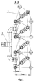
На фиг. 1 изображен общий вид теплообменного модуля, на фиг.2 показано его поперечное сечение. In FIG. 1 shows a General view of the heat exchange module, figure 2 shows its cross section.
Теплообменный модуль включает в себя делитель потока 1, соединенный со змеевиком 2 с помощью стандартных угольников 3 и контргаек 4. Змеевик S-образной формы выполнен из трех трубок 5, двух проходных штуцеров 6 и четырех угольников 3. Коллектор 7 конструктивно аналогичен делителю потока 1 и отличается от него лишь направлением движения нагреваемой воды. Положение коллектора 7 относительно концевых трубок 5 змеевика обеспечивается также с помощью угольников 3 и фиксируется контргайками 4, изготовленными согласно ГОСТ 8968-75. The heat exchange module includes a flow divider 1 connected to the
Всесторонний анализ конструкции различных вариантов теплообменного модуля выявил наиболее целесообразный из них, состоящий из четырех змеевиков, изготовленных из стальной оцинкованной водогазовой трубы по ГОСТ 3262-75 (например, трубы с условным проходом 15-20 мм и наружным диаметром 21,3-26,8 мм). A comprehensive analysis of the design of various options for the heat exchange module revealed the most appropriate of them, consisting of four coils made of galvanized steel water-gas pipe according to GOST 3262-75 (for example, pipes with nominal bore 15-20 mm and outer diameter 21.3-26.8 mm).
Теплообменный модуль работает следующим образом. The heat exchange module operates as follows.
Нагреваемая вода подается циркуляционным насосом контура испарителя теплового насоса в делитель потока 1, равномерно распределяющий ее между четырьмя змеевиками 2, полностью погруженными в поток греющего теплоносителя за счет предварительно установленной и зафиксированной с помощью контргаек 4 габаритной высоты модуля в соответствии с толщиной (высотой) слоя потока. Heated water is supplied by the circulation pump of the heat pump evaporator circuit to a flow divider 1, evenly distributing it between four
В процессе движения воды по трубкам 5, из которых 2/3 работают в режиме противотока, вода подогревается пропорционально среднему температурному напору и с помощью коллектора 7 подается в тепловой насос, трансформирующий низкопотенциальное утилизируемое тепло с температурой 15-20oС в теплоноситель с температурой порядка 50-70oС, что затем позволяет с успехом использовать его в системах отопления или горячего водоснабжения.During the movement of water through tubes 5, of which 2/3 operate in countercurrent mode, the water is heated in proportion to the average temperature head and, using collector 7, is supplied to a heat pump that transforms low-grade utilized heat with a temperature of 15-20 o C into a heat carrier with a temperature of the order of 50-70 o C, which then allows you to successfully use it in heating systems or hot water.
При уменьшении толщины (высоты) слоя греющего теплоносителя контргайки 4 "отпускаются", габаритная высота модуля уменьшается до требуемой величины за счет соответствующего поворота змеевиков 2, после чего контргайки вновь фиксируют змеевики в установленном положении. When the thickness (height) of the heating medium layer decreases, the locknuts 4 are released, the overall height of the module decreases to the required value due to the corresponding rotation of the
По сравнению с известными техническими решениями предлагаемая конструкция теплообменного модуля со змеевиками S-образной формы, выполненными посредством трех трубок, соединенных между собой проходными штуцерами и угольниками, которые обеспечивают движение воды в заданном направлении, а именно - в основном навстречу потоку теплоносителя, удлиняют ее путь в потоке греющего теплоносителя в 3 раза, могут иметь минимальные габариты по ширине за счет отказа от гибки трубок и использования стандартных угольников по ГОСТ 8946-75, позволяющих сократить расстояние между осями соседних трубок в два раза, позволяют оперативно изменять установочные габаритные размеры теплообменного модуля, просты в изготовлении и удобны при монтаже, применима для утилизация низкопотенциального тепла сточных вод с периодически изменяющейся высотой слоя, что наиболее характерно, например для грабельных отделений городских канализационных насосных станций. Compared with the known technical solutions, the proposed design of a heat exchanger module with S-shaped coils made by means of three tubes interconnected by passage fittings and elbows, which provide water movement in a given direction, namely, mainly towards the heat carrier flow, lengthens its path in the flow of the heating medium by 3 times, can have minimum dimensions in width due to the refusal to bend the tubes and the use of standard elbows in accordance with GOST 8946-75, allowing to cut To double the distance between the axes of adjacent tubes, they allow you to quickly change the installation dimensions of the heat exchange module, are easy to manufacture and convenient for installation, it is applicable for the utilization of low-grade heat of wastewater with a periodically changing layer height, which is most typical, for example, for rake sections of urban sewer pumping stations.
Предлагаемый теплообменный модуль может найти применение для отопления и горячего водоснабжения насосных станций, расположенных на больших расстояниях от центральных тепловых пунктов и требующих поэтому прокладки длинных трубопроводов. The proposed heat exchange module can be used for heating and hot water supply of pumping stations located at large distances from central heat points and therefore requiring the laying of long pipelines.
Claims (1)
Priority Applications (1)
| Application Number | Priority Date | Filing Date | Title |
|---|---|---|---|
| RU2001109989A RU2186309C1 (en) | 2001-04-12 | 2001-04-12 | Heat-transfer module |
Applications Claiming Priority (1)
| Application Number | Priority Date | Filing Date | Title |
|---|---|---|---|
| RU2001109989A RU2186309C1 (en) | 2001-04-12 | 2001-04-12 | Heat-transfer module |
Publications (1)
| Publication Number | Publication Date |
|---|---|
| RU2186309C1 true RU2186309C1 (en) | 2002-07-27 |
Family
ID=20248400
Family Applications (1)
| Application Number | Title | Priority Date | Filing Date |
|---|---|---|---|
| RU2001109989A RU2186309C1 (en) | 2001-04-12 | 2001-04-12 | Heat-transfer module |
Country Status (1)
| Country | Link |
|---|---|
| RU (1) | RU2186309C1 (en) |
Cited By (1)
| Publication number | Priority date | Publication date | Assignee | Title |
|---|---|---|---|---|
| RU2683058C2 (en) * | 2014-01-17 | 2019-03-26 | Юлия Аг | Heat exchanger for shower or bathtub |
-
2001
- 2001-04-12 RU RU2001109989A patent/RU2186309C1/en not_active IP Right Cessation
Cited By (1)
| Publication number | Priority date | Publication date | Assignee | Title |
|---|---|---|---|---|
| RU2683058C2 (en) * | 2014-01-17 | 2019-03-26 | Юлия Аг | Heat exchanger for shower or bathtub |
Similar Documents
| Publication | Publication Date | Title |
|---|---|---|
| US20190212062A1 (en) | Helical coil-on-tube heat exchanger | |
| Culha et al. | Heat exchanger applications in wastewater source heat pumps for buildings: A key review | |
| CA2541378C (en) | Geothermal aqueduct network | |
| US20040108096A1 (en) | Geothermal loopless exchanger | |
| JP2007010275A (en) | Geothermal heat pump type air-conditioner | |
| RU2104447C1 (en) | Method of heating of building interior and device for its realization | |
| RU2186309C1 (en) | Heat-transfer module | |
| RU2239129C1 (en) | Method of heat supply | |
| KR20130022770A (en) | Heat exchange system using air source heat and a sepitc waste source heat | |
| CN206208080U (en) | Separate heat pipe shower waste water residual heat recovery system | |
| KR100743364B1 (en) | Heat Pump System using Water Supply Pipe Line | |
| US11549716B2 (en) | Wastewater conditioning apparatus and method | |
| CN204787409U (en) | Bathing pool heat energy cyclic utilization special use cascading formula hot water unit | |
| RU2265776C1 (en) | Building heat supply system | |
| US20020144807A1 (en) | Effluent energy recovery system | |
| CN201059896Y (en) | Multi-strokes bundled tubes type sewage water heat exchanger | |
| RU178987U1 (en) | Waste Water Heat Recovery System | |
| US20170045237A1 (en) | Tank for energy recovery | |
| RU10247U1 (en) | HEAT EXCHANGE RADIATOR | |
| Gavilán del Amo et al. | Drain water heat recovery in a residential building | |
| RU73718U1 (en) | DEVICE FOR ENERGY SUPPLY OF PREMISES USING LOW-POTENTIAL ENERGY CARRIERS | |
| FI113203B (en) | A method of pumping heat in a cooling system, particularly a district cooling network, to recover the waste heat from the water circulating therein, and a device for that purpose | |
| PL230910B1 (en) | Vertical spiral heat exchanger | |
| SU1132140A1 (en) | Thermal siphon heat exchanger | |
| Gabor et al. | HEAT EXCHANGER UTILIZATIONS IN WASTEWATER HEAT RECOVERY FOR BUILDINGS: A KEY REVIEW |
Legal Events
| Date | Code | Title | Description |
|---|---|---|---|
| MM4A | The patent is invalid due to non-payment of fees |
Effective date: 20080413 |