RU2175463C2 - Direct-conversion radio receiver - Google Patents
Direct-conversion radio receiver Download PDFInfo
- Publication number
- RU2175463C2 RU2175463C2 RU97101907A RU97101907A RU2175463C2 RU 2175463 C2 RU2175463 C2 RU 2175463C2 RU 97101907 A RU97101907 A RU 97101907A RU 97101907 A RU97101907 A RU 97101907A RU 2175463 C2 RU2175463 C2 RU 2175463C2
- Authority
- RU
- Russia
- Prior art keywords
- signals
- phase
- circuit
- axes
- signal
- Prior art date
Links
Images
Abstract
Description
Настоящее изобретение относится к радиоприемнику прямого преобразования для использования в радиосистемах. The present invention relates to a direct conversion radio receiver for use in radio systems.
Известно использование прямого преобразования в радиоприемниках, которые избегают объемных и дорогих фильтров ПЧ. Использование РЧ-фильтров также значительно упрощается, и весь радиоприемник может быть объединен в единственную микросхему. It is known to use direct conversion in radios that avoid volumetric and expensive IF filters. The use of RF filters is also greatly simplified, and the entire radio receiver can be combined into a single chip.
На практике одним из основных препятствий успешной реализации прямого преобразования, особенно в цифровом коммуникационном оборудовании, является потребность в автоматической регулировке усиления (АРУ). В приемнике прямого преобразования АРУ должно быть получено из полосы частот модулирующих сигналов, что часто делает его слишком медленным для применения с импульсными сигналами, обычно применяемыми в современных цифровых системах. In practice, one of the main obstacles to the successful implementation of direct conversion, especially in digital communication equipment, is the need for automatic gain control (AGC). In the direct conversion receiver, the AGC must be obtained from the frequency band of the modulating signals, which often makes it too slow to use with pulsed signals, usually used in modern digital systems.
На фиг. 1 изображена блок-схема, которая часто используется в приемниках поискового вызова (пейджинговых) с малой скоростью передачи данных, и включает в себя антенну 2, соединенную с входом блокирующего фильтра 4, выход которого подсоединен ко входу усилителя 6. Выходной сигнал усилителя подается на вход смесителей 8, 10 соответственно, которые принимают на второй вход выходной сигнал гетеродина 12. Смеситель 8 принимает сигнал, который отличается по фазе от сигнала гетеродина 12 на 0o, а смеситель 10 принимает сигнал, который отличается по фазе от сигнала гетеродина 12 на 90o. Выходы смесителей 8 и 10 подаются соответственно на вход фильтров низких частот 14, 16, выходы которых подсоединены к ограничителям 18, 20 соответственно. Выходной сигнал ограничителя 18 является синфазным сигналом I, а выходной сигнал ограничителя 20 является квадратурным фазовым сигналом Q. Описанная схема, таким образом, не требует никакого АРУ.In FIG. 1 shows a block diagram, which is often used in paging receivers (paging) with a low data rate, and includes an antenna 2 connected to the input of the blocking filter 4, the output of which is connected to the input of the amplifier 6. The output signal of the amplifier is fed to the input mixers 8, 10, respectively, which receive the output signal of the local oscillator 12 at the second input. The mixer 8 receives a signal that differs in phase from the signal of the local oscillator 12 by 0 o , and mixer 10 receives a signal that differs in phase from the signal la heterodyne 12 at 90 o . The outputs of the mixers 8 and 10 are respectively supplied to the input of the low-pass filters 14, 16, the outputs of which are connected to the limiters 18, 20, respectively. The output signal of the limiter 18 is an in-phase signal I, and the output signal of the limiter 20 is a quadrature phase signal Q. The described circuit thus does not require any AGC.
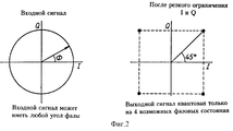
Если входные сигналы приемника являются частотно-манипулированными (FSK, ЧМн) сигналами, это может быть представлено в векторном виде так, как изображено на фиг. 2. Диаграмма слева на фиг. 2 изображает, что входной сигнал может иметь любой фазовый угол, в то время как выходные сигналы после резкого ограничения - сигналы I и Q - являются квантованными в любом из четырех возможных состояний, как изображено на правой диаграмме на фиг. 2. If the receiver input signals are frequency-manipulated (FSK, FSK) signals, this can be represented in vector form as shown in FIG. 2. The diagram on the left in FIG. 2 shows that the input signal can have any phase angle, while the output signals after a sharp restriction — signals I and Q — are quantized in any of the four possible states, as shown in the right diagram in FIG. 2.
Для того, чтобы демодулировать ЧМн сигнал, необходимо установить направление поворота вектора. Это является открытым (простым) в пейджинговых системах, где индекс модуляции является высоким, поэтому вектор будет вращаться несколько периодов для каждого бита данных. Ограниченные выходные сигналы I и Q затем становятся импульсами прямоугольной формы со сдвигом фазы на 90o друг к другу, или опережающими или запаздывающими, в зависимости от направления вращения. С помощью сравнения ограниченных сигналов I и Q на фазочувствительном детекторе (например D-триггере) может быть определена полярность разности фаз, а следовательно, может быть восстановлена модуляция.In order to demodulate the FSK signal, it is necessary to establish the direction of rotation of the vector. This is open (simple) in paging systems where the modulation index is high, so the vector will rotate several periods for each bit of data. The limited output signals I and Q then become rectangular pulses with a phase shift of 90 ° to each other, or leading or lagging, depending on the direction of rotation. By comparing the limited I and Q signals on a phase-sensitive detector (for example, a D-trigger), the polarity of the phase difference can be determined, and therefore, modulation can be restored.
Однако в более спектрально эффективных схемах с низким индексом модуляции, например схемах частотной манипуляции по Гауссу (GFSK), вектор может вращаться до 50o на бит данных. Это означает, что вектор может оставаться целиком в одном квадранте, поэтому изменений в выходных сигналах ограничителей нет. В этом случае данные являются невосстанавливаемыми.However, in more spectrally efficient schemes with a low modulation index, such as Gaussian frequency shift keying (GFSK) schemes, the vector can rotate up to 50 o per data bit. This means that the vector can remain entirely in one quadrant, so there are no changes in the output signals of the limiters. In this case, the data is not recoverable.
Задачей настоящего изобретения является создание приемника прямого преобразования для использования с сигналами фазовой модуляции, который не требует АРУ. An object of the present invention is to provide a direct conversion receiver for use with phase modulation signals, which does not require AGC.
Согласно настоящему изобретению создан приемник, содержащий средство для приема входного сигнала, переданного через радиосреду, средство для генерации синфазного и квадратурного фазовых сигналов из принятого входного сигнала и средство для генерации синфазного и квадратурного фазовых выходных сигналов в форме импульсов сильно ограниченных сигналов, отличающийся тем, что приемник включает в себя схемное средство, сконструированное для генерации дополнительных осей, являющихся промежуточными к осям синфазного и квадратурного фазовых сигналов, из которых генерируются импульсные сильно ограниченные сигналы, и средство декодирования, сконструированное для приема импульсов сильно ограниченных сигналов и сконструированное для генерации данных, соответствующих принятому радиосигналу. According to the present invention, there is provided a receiver comprising means for receiving an input signal transmitted through a radio medium, means for generating in-phase and quadrature phase signals from a received input signal, and means for generating in-phase and quadrature phase output signals in the form of pulses of strongly limited signals, characterized in that the receiver includes circuit means designed to generate additional axes that are intermediate to the in-phase and quadrature phase axes x signals from which pulsed strongly limited signals are generated, and decoding means designed to receive pulses of strongly limited signals and designed to generate data corresponding to the received radio signal.
Это схемное средство может включать в себя схемы первого и второго сумматоров, первая из которых предназначена для суммирования синфазного и квадратурного фазовых сигналов, из которых второй сконструирован для вычитания синфазного и квадратурного фазовых сигналов, посредством этого генерируя сигналы, имеющие оси, которые являются промежуточными к осям синфазного и квадратурного фазовых сигналов. This circuit means may include circuits of the first and second adders, the first of which is designed to sum the common-mode and quadrature phase signals, of which the second is designed to subtract the common-mode and quadrature phase signals, thereby generating signals having axes that are intermediate to the axes in-phase and quadrature phase signals.
Схемное средство может включать в себя рациометрический сумматор для генерации восьми осей, промежуточных к осям синфазного и квадратурного фазовых сигналов. The circuit means may include a ratiometric adder for generating eight axes intermediate to the axes of the in-phase and quadrature phase signals.
В дальнейшем изобретение поясняется наилучшими вариантами его воплощения со ссылками на сопровождающие чертежи, на которых:
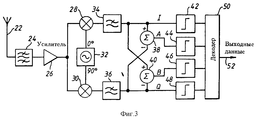
фиг. 3 изображает приемник прямого преобразования с использованием четырех ограничителей согласно изобретению,
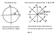
фиг. 4 изображает векторное представление сигнала в четырехосном приемнике согласно изобретению,
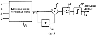
фиг. 5 изображает блок-схему ЧМн декодера согласно изобретению,
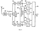
фиг. 6 изображает блок-схему приемника прямого преобразования, использующего "n" ограничителей согласно изобретению,
фиг. 7 изображает блок-схему П/4-DQPSK (относительной квадратурной фазовой манипуляции) декодера согласно изобретению.The invention is further illustrated by the best options for its implementation with reference to the accompanying drawings, in which:
FIG. 3 shows a direct conversion receiver using four limiters according to the invention,
FIG. 4 is a vectorial representation of a signal in a four-axis receiver according to the invention,
FIG. 5 shows a block diagram of an FSK decoder according to the invention,
FIG. 6 depicts a block diagram of a direct conversion receiver using “n” limiters according to the invention,
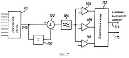
FIG. 7 depicts a block diagram of a P / 4-DQPSK (relative quadrature phase shift keying) decoder according to the invention.
На фиг. 3 изображена блок-схема приемника прямого преобразования, использующего четыре ограничителя. Изображенный приемник преодолевает недостаток предшествующего уровня техники с помощью эффективного введения дополнительных осей, являющихся промежуточными к осям синфазного и квадратурного фазовых сигналов. Простейшей реализацией этого является добавить две дополнительные оси под 45o и 135o с помощью определения суммы и разности синфазного I и квадратурного Q фазовых сигналов, сильно (амплитудное) ограничивая два новых сигнала, обозначенных A и B, как изображено на чертеже. Приемник содержит антенну 22, подсоединенную к блокирующему фильтру 24, выход которого подается на усилитель 26. Выходной сигнал усилителя подается на первый вход схемы смесителей 28, 30 соответственно. Схема смесителя 28 принимает синфазный сигнал 1 от гетеродина 32, а схема смесителя 30 принимает квадратурный фазовый сигнал Q от гетеродина 32. Выходной сигнал с каждой схемы смесителей 28, 30 подается на вход фильтров низких частот 34, 36 соответственно. Выходной сигнал фильтра 34 представляет собой синфазный сигнал и подается на вход ограничителя 42, на вход схемы сумматора 38 и на вход схемы сумматора 40. Аналогично выходной сигнал фильтра 36 представляет собой квадратурный фазовый сигнал и подается на вход ограничителя 48, на дополнительный вход схемы сумматора 40 и на дополнительный вход схемы сумматора 38. Сумматор 38 генерирует выходной сигнал А, который является суммой двух входных сигналов, а сумматор 40 генерирует выходной сигнал В, который является разностью двух входных сигналов. Выходной сигнал сумматора 38 подается на ограничитель 44, а выходной сигнал сумматора 40 подается на вход ограничителя 46. Каждый из ограничителей 42-48 генерирует выходной сигнал, который подается на декодер 50, с которого сигнал выходных данных выдается на выходную линию 52.In FIG. 3 shows a block diagram of a direct conversion receiver using four limiters. The illustrated receiver overcomes the drawback of the prior art by efficiently introducing additional axes that are intermediate to the axes of the in-phase and quadrature phase signals. The simplest implementation of this is to add two additional axes at 45 o and 135 o by determining the sum and difference of the in-phase I and quadrature Q phase signals, strongly (amplitude) limiting the two new signals indicated by A and B, as shown in the drawing. The receiver includes an
На фиг. 4 изображена векторная диаграмма, относящаяся к фиг. 3. При наличии четырех осей существует восемь секторов, а сильно ограниченные сигналы в действительности представляют собой сигналы, квантованные в восемь возможных фазовых состояний, разделенных 45o. Когда входной сигнал является GFSK модулированным сигналом, вектор будет пересекать по меньшей мере одну ось, поэтому направление вращения может быть установлено, а данные восстановлены.In FIG. 4 is a vector diagram related to FIG. 3. If there are four axes, there are eight sectors, and the strongly limited signals are actually signals quantized into eight possible phase states, separated by 45 o . When the input signal is a GFSK modulated signal, the vector will cross at least one axis, so the direction of rotation can be set and the data restored.
На фиг. 4 диаграмма слева изображает, что входной сигнал может иметь любой фазовый угол, а диаграмма справа изображает, что после сильного ограничения выходной сигнал квантуется на восемь возможных фазовых состояний. In FIG. 4, the diagram on the left shows that the input signal can have any phase angle, and the diagram on the right shows that after a strong limitation, the output signal is quantized into eight possible phase states.
Декодирование данных может быть получено в цифровом виде из двоичных сигналов на выходах ограничителей 42-48 на фиг. 4, и декодирование показано со ссылкой на фиг. 5. Фиг. 5 изображает ЧМн декодер, содержащий комбинационную логическую схему 54, которая принимает входные сигналы I, A, B и Q от ограничителей 42-48 на фиг. 4. Выход комбинационной логической схемы подсоединен ко входу схемы 56 задержки и ко входу схемы 58 суммирования. Выходной сигнал схемы 56 задержки подсоединен к дополнительному входу схемы 58 суммирования. Выход схемы 58 суммирования подсоединен ко входу схемы 60 усреднения, выходной сигнал которого подается на амплитудный ограничитель 62, с выхода которого данные передаются на выходную линию 64. Data decoding can be obtained digitally from binary signals at the outputs of limiters 42-48 in FIG. 4, and decoding is shown with reference to FIG. 5. FIG. 5 depicts an FSK decoder comprising a
Простая комбинационная логическая схема может применяться для получения выходного двоичного сектора с номером 0 до 7, представляющего собой сектор фазы, в котором находится мгновенное значение сигнала. Вычитая (по модулю 8) значение предыдущего сектора из значения текущего сектора, получаются серии импульсов, которые являются отрицательными или положительными в зависимости от направления вращения. В действительности образуется дискриминатор частотной выборки. Чтобы избежать наложения, элемент задержки должен иметь продолжительность менее половины битового периода. Импульсная последовательность затем усредняется в схеме 60 и ограничивается схемой 62 для выделения данных. A simple combinational logic circuit can be used to obtain the output binary sector numbered 0 to 7, which is the phase sector in which the instantaneous value of the signal is located. Subtracting (modulo 8) the value of the previous sector from the value of the current sector, we obtain a series of pulses that are negative or positive depending on the direction of rotation. In fact, the discriminator of the frequency sample is formed. To avoid overlapping, the delay element must have a duration of less than half the bit period. The pulse sequence is then averaged in
В схемах модуляции, в которых фазовый сдвиг на бит меньше (например π/4-DQPSK или GFSK с очень низким коэффициентом ВТ, где B является шириной полосы пропускания фильтра модуляции, а T является битовым периодом), способ может быть расширен с помощью введения большего количества осей, улучшая таким образом разрешение фазы. Эта концепция показана на фиг. 6. In modulation schemes in which the phase shift is lower by a bit (for example, π / 4-DQPSK or GFSK with a very low BT coefficient, where B is the bandwidth of the modulation filter and T is the bit period), the method can be expanded by introducing a larger number of axes, thus improving phase resolution. This concept is shown in FIG. 6.
На примере фиг. 6 будет пояснено дополнительное воплощение настоящего изобретения и описан приемник прямого преобразования, использующий "n" ограничителей. In the example of FIG. 6, an additional embodiment of the present invention will be explained and a direct conversion receiver using “n” delimiters will be described.
Приемник содержит антенну 66, которая подсоединена к РЧ-фильтру 68, выход которого подсоединен к входному сигналу усилителя 70. Выходной сигнал усилителя подается на вход схемы смесителя 72 и на вход схемы смесителя 74. Вторые входы смесителей 72, 74 принимают выходные сигналы от гетеродина 76 в форме синфазного сигнала, поданного на смеситель 72, и квадратурного фазового сигнала, поданного на смеситель 74. Выходной сигнал схемы смесителя 72 подается на фильтр 78 низких частот, и аналогично выходной сигнал схемы 74 смесителя подается на фильтр низких частот 80. Выходные сигналы фильтров 78, 80 каждый подаются на рациометрический сумматор 82 соответственно и на вход ограничителя 84 и ограничителя 92 соответственно. Рациометрический сумматор 82 генерирует ряд выходных сигналов, каждый из которых подается на вход ограничителей 86-90 соответственно. Выходной сигнал каждого ограничителя подается на вход декодера 94, который предназначен для генерации выходного сигнала на выходную линию 96. The receiver includes an antenna 66, which is connected to an
При π/4-DQPSK модуляции фазовый сдвиг на символ составляет ±45 или ±135 в зависимости от битовой парной комбинации (00, 01, 10, 11). В конструкции приемника, изображенной на фиг. 6, потребуются минимум 8 осей (8 ограничителей), давая 16 секторов и разрешение фазы в 22.5o. Декодирование будет также слабо изменяться от ЧМн версии, следовательно три порога точности потребуются для детектирования амплитуды, а также полярности сдвига фазы. Декодер изображен на фиг. 7.With π / 4-DQPSK modulation, the phase shift per symbol is ± 45 or ± 135 depending on the bit pair combination (00, 01, 10, 11). In the receiver structure shown in FIG. 6, a minimum of 8 axes (8 limiters) will be required, giving 16 sectors and a phase resolution of 22.5 o . Decoding will also vary slightly from the FMN version, therefore, three accuracy thresholds will be required to detect the amplitude, as well as the phase shift polarity. The decoder is shown in FIG. 7.
Схема декодера (фиг. 7) содержит логическую схему 98, которая принимает входной сигнал от схем ограничителей 84-92 (фиг. 6). Выходной сигнал логической схемы подается на вход сумматора 102 и на вход схемы задержки 100. Выходной сигнал схемы 100 задержки подается на дополнительный вход сумматора 102. Выходной сигнал сумматора 102 подается на вход схемы 104 усреднения, выходной сигнал которой подается на три пороговых устройства 106, 108, 110, которые предназначены для сравнения выходного сигнала схемы 104 усреднения с пороговым сигналом, поданным на ее второй вход. Выходной сигнал каждой пороговой схемы 106-110 подается на вход логической схемы 112 соответственно, которая предназначена для генерирования выходных битовых данных на выходную линию 114 и на выходную линию 116. The decoder circuit (Fig. 7) contains a
Специалистами могут быть сделаны различные модификации и изменения в рамках настоящего изобретения. Приемник предназначен в первую очередь для схем фазовой или частотной модуляции. Однако в системах, где изменение огибающей должно быть сохранено (например, для выравнивания), огибающая сигнала может быть получена из выходных сигналов индикатора амплитуды принятого сигнала ограничителя. Так как это должна быть огибающая логарифмического сжатия, то необходима антилогарифмическая функция для восстановления линейного амплитудного изменения. Various modifications and changes can be made by those skilled in the art within the scope of the present invention. The receiver is primarily intended for phase or frequency modulation schemes. However, in systems where the envelope change must be saved (for example, for alignment), the envelope of the signal can be obtained from the output signals of the amplitude indicator of the received limiter signal. Since this should be an envelope of logarithmic compression, an antilogarithmic function is necessary to restore the linear amplitude change.
Claims (8)
Priority Applications (1)
| Application Number | Priority Date | Filing Date | Title |
|---|---|---|---|
| RU97101907A RU2175463C2 (en) | 1995-05-10 | 1995-05-10 | Direct-conversion radio receiver |
Applications Claiming Priority (1)
| Application Number | Priority Date | Filing Date | Title |
|---|---|---|---|
| RU97101907A RU2175463C2 (en) | 1995-05-10 | 1995-05-10 | Direct-conversion radio receiver |
Publications (2)
| Publication Number | Publication Date |
|---|---|
| RU97101907A RU97101907A (en) | 1999-04-27 |
| RU2175463C2 true RU2175463C2 (en) | 2001-10-27 |
Family
ID=20189745
Family Applications (1)
| Application Number | Title | Priority Date | Filing Date |
|---|---|---|---|
| RU97101907A RU2175463C2 (en) | 1995-05-10 | 1995-05-10 | Direct-conversion radio receiver |
Country Status (1)
| Country | Link |
|---|---|
| RU (1) | RU2175463C2 (en) |
Cited By (1)
| Publication number | Priority date | Publication date | Assignee | Title |
|---|---|---|---|---|
| RU2542939C1 (en) * | 2013-10-09 | 2015-02-27 | Общество с ограниченной ответственностью "Алсет Веллен" | Direct transform receiver having quadrature three-phase architecture, method for direct signal transform using said receiver and method of controlling tuning of said receiver |
-
1995
- 1995-05-10 RU RU97101907A patent/RU2175463C2/en active
Non-Patent Citations (1)
| Title |
|---|
| ОКУНЕВ Ю.Б. Теория фазоразностной модуляции. - М.: Связь, 1979, с. 127 рис. 4.7, с. 147 рис. 4.20. * |
Cited By (1)
| Publication number | Priority date | Publication date | Assignee | Title |
|---|---|---|---|---|
| RU2542939C1 (en) * | 2013-10-09 | 2015-02-27 | Общество с ограниченной ответственностью "Алсет Веллен" | Direct transform receiver having quadrature three-phase architecture, method for direct signal transform using said receiver and method of controlling tuning of said receiver |
Similar Documents
| Publication | Publication Date | Title |
|---|---|---|
| CA2194695C (en) | A direct conversion receiver | |
| US3993956A (en) | Digital detection system for differential phase shift keyed signals | |
| EP0333266B1 (en) | A direct conversion receiver | |
| CA2173530C (en) | Modulation and demodulation method, modulator and demodulator | |
| US4887280A (en) | System for detecting the presence of a signal of a particular data rate | |
| US5640427A (en) | Demodulator | |
| US4647864A (en) | Variable-delay, sine-cosine non-coherent demodulator | |
| US4336500A (en) | MSK Demodulator frequency acquistion apparatus and method | |
| US4246653A (en) | In-phase quadrature demodulator for CPSK signals | |
| US6823026B2 (en) | Apparatus and method for baseband detection | |
| JP3902661B2 (en) | Receiver, demodulator, and demodulation method | |
| JPH0621992A (en) | Demodulator | |
| EP0484914B1 (en) | Demodulator and method for demodulating digital signals modulated by a minimum shift keying | |
| US4439737A (en) | Phase locked loop, as for MPSK signal detector | |
| RU2175463C2 (en) | Direct-conversion radio receiver | |
| US5598125A (en) | Method for demodulating a digitally modulated signal and a demodulator | |
| US4748641A (en) | Suppressed carrier modulation method | |
| GB1594320A (en) | Method and device for measuring the difference in envelope delay at the extreme frequences of channel passband in a data transmission system | |
| US6002725A (en) | M-ary FSK receiver | |
| CN1066870C (en) | Direct conversion receiver | |
| KR100368013B1 (en) | Direct conversion receiver | |
| US5982200A (en) | Costas loop carrier recovery circuit using square-law circuits | |
| RU2808227C1 (en) | Amplitude shift keying demodulator | |
| JP2696948B2 (en) | Carrier recovery circuit | |
| JPH05304542A (en) | Demodulation method and demodulator |