RU2166782C2 - Single-mode optical waveguide with large effective area ( versions ) - Google Patents
Single-mode optical waveguide with large effective area ( versions ) Download PDFInfo
- Publication number
- RU2166782C2 RU2166782C2 RU96123578/28A RU96123578A RU2166782C2 RU 2166782 C2 RU2166782 C2 RU 2166782C2 RU 96123578/28 A RU96123578/28 A RU 96123578/28A RU 96123578 A RU96123578 A RU 96123578A RU 2166782 C2 RU2166782 C2 RU 2166782C2
- Authority
- RU
- Russia
- Prior art keywords
- refractive index
- profile
- core region
- optical waveguide
- waveguide fiber
- Prior art date
Links
Images
Classifications
-
- G—PHYSICS
- G02—OPTICS
- G02B—OPTICAL ELEMENTS, SYSTEMS OR APPARATUS
- G02B6/00—Light guides; Structural details of arrangements comprising light guides and other optical elements, e.g. couplings
- G02B6/02—Optical fibres with cladding with or without a coating
- G02B6/036—Optical fibres with cladding with or without a coating core or cladding comprising multiple layers
- G02B6/03605—Highest refractive index not on central axis
- G02B6/03611—Highest index adjacent to central axis region, e.g. annular core, coaxial ring, centreline depression affecting waveguiding
-
- G—PHYSICS
- G02—OPTICS
- G02B—OPTICAL ELEMENTS, SYSTEMS OR APPARATUS
- G02B6/00—Light guides; Structural details of arrangements comprising light guides and other optical elements, e.g. couplings
- G02B6/02—Optical fibres with cladding with or without a coating
-
- G—PHYSICS
- G02—OPTICS
- G02B—OPTICAL ELEMENTS, SYSTEMS OR APPARATUS
- G02B6/00—Light guides; Structural details of arrangements comprising light guides and other optical elements, e.g. couplings
- G02B6/02—Optical fibres with cladding with or without a coating
- G02B6/02004—Optical fibres with cladding with or without a coating characterised by the core effective area or mode field radius
- G02B6/02009—Large effective area or mode field radius, e.g. to reduce nonlinear effects in single mode fibres
- G02B6/02014—Effective area greater than 60 square microns in the C band, i.e. 1530-1565 nm
- G02B6/02019—Effective area greater than 90 square microns in the C band, i.e. 1530-1565 nm
-
- G—PHYSICS
- G02—OPTICS
- G02B—OPTICAL ELEMENTS, SYSTEMS OR APPARATUS
- G02B6/00—Light guides; Structural details of arrangements comprising light guides and other optical elements, e.g. couplings
- G02B6/02—Optical fibres with cladding with or without a coating
- G02B6/02214—Optical fibres with cladding with or without a coating tailored to obtain the desired dispersion, e.g. dispersion shifted, dispersion flattened
- G02B6/02219—Characterised by the wavelength dispersion properties in the silica low loss window around 1550 nm, i.e. S, C, L and U bands from 1460-1675 nm
- G02B6/02223—Dual window fibres, i.e. characterised by dispersion properties around 1550 nm and in at least another wavelength window, e.g. 1310 nm
-
- G—PHYSICS
- G02—OPTICS
- G02B—OPTICAL ELEMENTS, SYSTEMS OR APPARATUS
- G02B6/00—Light guides; Structural details of arrangements comprising light guides and other optical elements, e.g. couplings
- G02B6/02—Optical fibres with cladding with or without a coating
- G02B6/028—Optical fibres with cladding with or without a coating with core or cladding having graded refractive index
- G02B6/0281—Graded index region forming part of the central core segment, e.g. alpha profile, triangular, trapezoidal core
-
- G—PHYSICS
- G02—OPTICS
- G02B—OPTICAL ELEMENTS, SYSTEMS OR APPARATUS
- G02B6/00—Light guides; Structural details of arrangements comprising light guides and other optical elements, e.g. couplings
- G02B6/02—Optical fibres with cladding with or without a coating
- G02B6/028—Optical fibres with cladding with or without a coating with core or cladding having graded refractive index
- G02B6/0286—Combination of graded index in the central core segment and a graded index layer external to the central core segment
-
- G—PHYSICS
- G02—OPTICS
- G02B—OPTICAL ELEMENTS, SYSTEMS OR APPARATUS
- G02B6/00—Light guides; Structural details of arrangements comprising light guides and other optical elements, e.g. couplings
- G02B6/02—Optical fibres with cladding with or without a coating
- G02B6/036—Optical fibres with cladding with or without a coating core or cladding comprising multiple layers
- G02B6/03616—Optical fibres characterised both by the number of different refractive index layers around the central core segment, i.e. around the innermost high index core layer, and their relative refractive index difference
- G02B6/03622—Optical fibres characterised both by the number of different refractive index layers around the central core segment, i.e. around the innermost high index core layer, and their relative refractive index difference having 2 layers only
- G02B6/03633—Optical fibres characterised both by the number of different refractive index layers around the central core segment, i.e. around the innermost high index core layer, and their relative refractive index difference having 2 layers only arranged - -
Abstract
Description
Изобретение относится к одномодовому оптическому волноводному волокну с большой эффективной площадью Aэфф для применения в области связи. В частности, изобретение относится к одномодовому оптическому волноводному волокну с большой эффективной площадью для рабочего окна как на длине волны 1300 нм, так и 1550 нм.The invention relates to a single-mode optical waveguide fiber with a large effective area A eff for use in the field of communication. In particular, the invention relates to a single-mode optical waveguide fiber with a large effective area for the working window both at a wavelength of 1300 nm and 1550 nm.
В одномодовом волноводе с большой эффективной площадью меньше проявляются нелинейные оптические эффекты, в том числе фазовая автомодуляция, четырехволновое смешение, перекрестная фазовая модуляция и процессы нелинейного рассеяния. В случае четырехволнового смешения важным является также положение длины волны нулевой дисперсии. Каждый из этих эффектов вызывает искажение сигнала в системах большой мощности. In a single-mode waveguide with a large effective area, nonlinear optical effects appear, including phase self-modulation, four-wave mixing, cross-phase modulation, and nonlinear scattering processes. In the case of four-wave mixing, the position of the zero dispersion wavelength is also important. Each of these effects causes signal distortion in high power systems.
Процессы рассеяния, которые искажают сигнал, в общем виде описываются уравнением, содержащим член exp (cP/Aэфф), где c - постоянная, P - мощность сигнала. Другие нелинейные эффекты описываются уравнениями, которые включают отношение P/Aэфф в качестве множителя. Таким образом, увеличение Aэфф вызывает уменьшение вклада нелинейных эффектов в искажение светового сигнала.Scattering processes that distort the signal are generally described by an equation containing the term exp (cP / A eff ), where c is a constant, P is the signal power. Other non-linear effects are described by equations that include the P / A eff ratio as a factor. Thus, an increase in A eff causes a decrease in the contribution of nonlinear effects to the distortion of the light signal.
Требование индустрии связи по увеличению объема информации, передаваемого на большие расстояния без использования регенераторов, привело к переоценке подхода к разработке профилей показателя преломления одномодовых волокон. Сущность этой переоценки заключается в том, чтобы создать оптические волноводы, которые:
- уменьшают нелинейные эффекты, указанные выше,
- совместимы с оптическими усилителями и
- сохраняют требуемые характеристики оптических волноводов, в частности, малое затухание, высокую прочность, усталостную прочность и устойчивость к изгибу. Эта разработка предназначалась для диапазонов длин волн, которые включают рабочее окно на длине волны 1550 нм. Однако, так как многие надежные приборы, включая лазеры, оптические усилители, приемники, передатчики и регенераторы, разработаны для использования на длине волны около 1300 нм, то необходимо уменьшить нелинейные эффекты и на этой более короткой рабочей длине волны.The requirement of the communications industry to increase the amount of information transmitted over long distances without the use of regenerators has led to a reassessment of the approach to the development of refractive index profiles of single-mode fibers. The essence of this reassessment is to create optical waveguides that:
- reduce the non-linear effects indicated above,
- compatible with optical amplifiers and
- retain the required characteristics of the optical waveguides, in particular, low attenuation, high strength, fatigue strength and resistance to bending. This development was intended for wavelength ranges that include a working window at a wavelength of 1550 nm. However, since many reliable instruments, including lasers, optical amplifiers, receivers, transmitters and regenerators, are designed for use at a wavelength of about 1300 nm, it is necessary to reduce non-linear effects at this shorter working wavelength.
Таким образом, для рабочих окон на длинах волн около 1300 нм и 1550 нм имеется потребность в одномодовом оптическом волноводном волокне с большой эффективной площадью. Thus, for working windows at wavelengths of about 1300 nm and 1550 nm, there is a need for a single-mode optical waveguide fiber with a large effective area.
Предшествующие разработки, такие как описанные в заявке на патент США N 08/378780, включают некоторые основные концепции конструкции сердцевины, состоящей из нескольких участков, впервые описанной в патенте США N 4715679. Для класса конструкций сердцевины, описанного в вышеуказанной заявке США N 08/378780, были созданы волноводы с большей эффективной площадью. В этой заявке была описана конкретная конструкция, включающая по меньшей мере одну область сердцевины, имеющую минимальный показатель преломления, меньший показателя преломления оболочки. Prior art designs, such as those described in US Patent Application No. 08/378780, include some basic concepts of a multi-section core structure first described in US Pat. No. 4,715,679. For the class of core structures described in US Application No. 08/378780 above. , waveguides with a larger effective area were created. This application has described a specific structure comprising at least one core region having a minimum refractive index lower than the shell refractive index.
Кроме того, в заявке на патент США N 08/287262 описаны конкретные признаки семейства профилей показателя преломления, у которых максимальный показатель преломления расположен на расстоянии от центральной оси волноводного волокна. In addition, U.S. Patent Application No. 08/287262 describes specific features of a family of refractive index profiles in which the maximum refractive index is located at a distance from the center axis of the waveguide fiber.
Новые описанные здесь профили показателя преломления являются, однако, другими вариантами профилей из патента США N 4715679. Основополагающая концепция сердцевины, состоящей из нескольких участков, достаточно универсальна для создания новых конструкций сердцевины согласно данному изобретению, которые разработаны с целью ограничения нелинейных эффектов для рабочего окна как на длине волны 1300 нм, так и 1550 нм. The new refractive index profiles described here, however, are other profile options from US Pat. No. 4,715,679. The fundamental concept of a multi-segment core is versatile enough to create new core designs according to this invention that are designed to limit non-linear effects for the working window as at a wavelength of 1300 nm, and 1550 nm.
Определения
Эффективная площадь равна
![]()
The effective area is
![]()
Эффективный диаметр Dэфф может быть определен, как
Dэфф=2(Aэфф/ π )1/2.The effective diameter D eff can be defined as
D eff = 2 (A eff / π) 1/2 .
- Площадь поля моды Amf= π (Dmf/2)2, где Dmf - диаметр поля моды, измеренный по II методу Петермана, где 2w=Dmf и ![]()
- Ширина участка профиля показателя преломления равна расстоянию между двумя вертикальными линиями, проведенными от начальной и конечной точек профиля показателя преломления до горизонтальной оси графика зависимости показателя преломления от радиуса.- The area of the mode field A mf = π (D mf / 2) 2 , where D mf is the diameter of the mode field measured according to the II Peterman method, where 2w = D mf and ![]()
- The width of the section of the profile of the refractive index is equal to the distance between two vertical lines drawn from the start and end points of the profile of the refractive index to the horizontal axis of the graph of the dependence of the refractive index on the radius.
- Коэффициент Δ% (относительный показатель преломления) равен Δ% = [(n1 2-nc)2)/2n1 2] • 100, где n1 - показатель преломления сердцевины и nc - показатель преломления оболочки. Если не указано иное, то n1 равен максимальному показателю преломления области сердцевины, характеризуемой параметром Δ%.- The coefficient Δ% (relative refractive index) is Δ% = [(n 1 2 -n c ) 2 ) / 2n 1 2 ] • 100, where n 1 is the refractive index of the core and n c is the refractive index of the shell. Unless otherwise specified, then n 1 is equal to the maximum refractive index of the core region, characterized by the parameter Δ%.
- Профиль показателя преломления обычно имеет соответствующий эффективный профиль показателя преломления, который имеет другую форму. Эффективный профиль показателя преломления может быть использован вместо соответствующего ему профиля показателя преломления без изменения режима работы волновода, см. работу "Single Mode Fiber Optics, Marcel Dekker Inc., Luc B. Jeunhomme, 1990, p. 32, section 1.3.2''. - The refractive index profile usually has a corresponding effective refractive index profile, which has a different shape. An effective refractive index profile can be used in place of its corresponding refractive index profile without changing the waveguide operating mode, see "Single Mode Fiber Optics, Marcel Dekker Inc., Luc B. Jeunhomme, 1990, p. 32, section 1.3.2 '' .
- Работоспособность при изгибе определяется по стандартному тесту, в котором измеряют затухание, вызванное намоткой волноводного волокна на катушку. В стандартом тесте определяются параметры волноводного волокна, имеющего один виток вокруг катушки диаметром 32 мм и сто витков вокруг катушки диаметром 75 мм. Максимально допустимое затухание, вызванное изгибом, обычно определяется для рабочего окна на длине волны около 1300 нм и около 1550 нм. - Bending performance is determined by the standard test, which measures the attenuation caused by winding the waveguide fiber onto a spool. The standard test determines the parameters of a waveguide fiber having one turn around a 32 mm diameter coil and one hundred turns around a 75 mm diameter coil. The maximum allowable attenuation caused by bending is usually determined for the working window at a wavelength of about 1300 nm and about 1550 nm.
- Альтернативным тестом на изгиб является тест на изгиб с помощью расположенных в ряд стержней, который используется для определения относительной устойчивости волноводного волокна к изгибу. Чтобы выполнить этот тест, измеряют затухание в волноводном волокне по существу без изгибов. Затем волноводное волокно вплетается в ряд стержней и снова измеряется затухание. Потери, вызванные изгибами, равны разнице между двумя измеренными значениями затухания. Ряд стержней является набором из 10 цилиндрических стержней, расположенных в один ряд и закрепленных в вертикальном положении на плоской поверхности. Расстояние между стержнями равно 5 мм, от центра до центра. Диаметр стержня равен 0,67 мм. Во время испытания прикладывается достаточное усилие, чтобы заставить волноводное волокно повторить форму части поверхности стержней. - An alternative bending test is a bending test using in-line rods, which is used to determine the relative resistance of a waveguide fiber to bending. To perform this test, the attenuation in the waveguide fiber is measured substantially without bending. Then the waveguide fiber is woven into a series of rods and attenuation is measured again. Losses caused by bending equal the difference between the two measured attenuation values. A row of rods is a set of 10 cylindrical rods arranged in one row and mounted vertically on a flat surface. The distance between the rods is 5 mm, from center to center. The diameter of the rod is 0.67 mm. During the test, sufficient force is applied to force the waveguide fiber to repeat the shape of part of the surface of the rods.
- Термин "острый минимум" относится к части профиля показателя преломления, который имеет V-образную или узкую U-образную форму. Острый минимум равен наименьшей величине показателя преломления части профиля показателя преломления. - The term “sharp minimum” refers to a portion of the profile of a refractive index that is V-shaped or narrow U-shaped. The sharp minimum is equal to the smallest value of the refractive index of a part of the profile of the refractive index.
- Термин "широкий минимум" относится к части профиля показателя преломления, который имеет широкую U-образную или L-образную форму. Широкий минимум является линией, проходящей через наименьшие значения части профиля показателя преломления. - The term "broad minimum" refers to a portion of the profile of the refractive index, which has a wide U-shaped or L-shaped. A wide minimum is a line passing through the smallest values of a part of the profile of the refractive index.
Первым объектом изобретения является одномодовое оптическое волноводное волокно, имеющее профиль показателя преломления сердцевины, максимальный показатель преломления у которого расположен на расстоянии от продольной центральной оси волновода. Профиль показателя преломления имеет острый минимум около центральной оси волновода и симметричен относительно центральной оси. Слой оболочки окружает сердцевину и завершает волноводную структуру. По меньшей мере одна часть профиля показателя преломления сердцевины имеет значения показателя преломления больше максимального показателя преломления оболочки, чтобы обеспечить распространение светового сигнала. The first object of the invention is a single-mode optical waveguide fiber having a core refractive index profile, the maximum refractive index of which is located at a distance from the longitudinal central axis of the waveguide. The profile of the refractive index has a sharp minimum near the central axis of the waveguide and is symmetrical about the central axis. A sheath layer surrounds the core and completes the waveguide structure. At least one part of the core refractive index profile has refractive index values greater than the maximum cladding refractive index to allow the propagation of the light signal.
В варианте выполнения этого первого объекта изобретения часть профиля показателя преломления между острым минимумом и максимумом показателя преломления является непрерывной кривой. В предпочтительном варианте непрерывная кривая является монотонной. Способы компенсации диффузии легирующей примеси из центра заготовки, такие как регулирование уровня легирования на стадии осаждения или контроль среды, окружающей заготовку из сажи, на стадии отверждения, известны из литературы. In an embodiment of this first aspect of the invention, the portion of the refractive index profile between the sharp minimum and maximum of the refractive index is a continuous curve. In a preferred embodiment, the continuous curve is monotonic. Methods of compensating for the diffusion of dopants from the center of the preform, such as adjusting the doping level in the deposition step or controlling the environment surrounding the carbon black preform in the curing step, are known from the literature.
Параметры семейства волноводных профилей для первого объекта изобретения следующие:
- радиус сердцевины в диапазоне примерно от 4-7 мкм,
- максимум Δ% в диапазоне примерно 0,35-0,55%,
- острый минимум Δ% менее примерно 0,20%.The parameters of the family of waveguide profiles for the first object of the invention are as follows:
- the radius of the core in the range from about 4-7 microns,
- maximum Δ% in the range of about 0.35-0.55%,
- an acute minimum Δ% less than about 0.20%.
Это семейство волноводов имеет следующие характеристики:
- длина волны нулевой дисперсии λ0 около 1300 нм,
- Dэфф более диаметра поля моды в диапазоне λ примерно 1530 - 1565 нм.This family of waveguides has the following characteristics:
- the wavelength of zero dispersion λ 0 about 1300 nm,
- D eff greater than the mode field diameter in the λ range of about 1530 - 1565 nm.
Другим объектом изобретения является одномодовое оптическое волноводное волокно, в котором первый и второй участок расположены симметрично относительно центральной оси волновода. Протяженность каждого участка определяется радиусом, проведенным от центральной оси до крайней точки участка. Каждому участку соответствует Δ%. Слой оболочки окружает сердцевину и имеет максимальный показатель преломления nc. По меньшей мере одна часть профиля показателя преломления одного из участков имеет показатель преломления больше nc По меньшей мере один участок имеет широкий минимум. Это семейство новых профилей показателя преломления дает возможность получить волноводное волокно, имеющее Aэфф на длине волны 1300 нм более 90 мкм2 и на длине волны 1550 нм более 110 мкм2. λ0 равно примерно 1300 нм.Another object of the invention is a single-mode optical waveguide fiber, in which the first and second section are located symmetrically relative to the Central axis of the waveguide. The length of each section is determined by the radius drawn from the central axis to the extreme point of the section. Each plot corresponds to Δ%. A shell layer surrounds the core and has a maximum refractive index of n c . At least one part of the refractive index profile of one of the regions has a refractive index greater than n c. At least one region has a broad minimum. This family of new refractive index profiles makes it possible to obtain a waveguide fiber having A eff at a wavelength of 1300 nm more than 90 μm 2 and at a wavelength of 1550 nm more than 110 μm 2 . λ 0 is approximately 1300 nm.
В предпочтительном варианте выполнения этого второго объекта изобретения первый участок сердцевины по существу имеет постоянное значение показателя преломления, равное n1. Второй участок имеет максимальный показатель преломления n2, причем n2>n1.In a preferred embodiment of this second aspect of the invention, the first portion of the core essentially has a constant refractive index value of n 1 . The second section has a maximum refractive index of n 2 , with n 2 > n 1 .
В наиболее предпочтительном варианте выполнения второго объекта изобретения второй участок профиля показателя преломления имеет трапецеидальную форму. Внешний радиус первого участка, имеющего по существу постоянный показатель преломления, находится в диапазоне примерно 1,5 - 1,9 мкм, а n1 по существу равен nc. Внешний радиус второго участка сердцевины находится в диапазоне 3,8 - 5 мкм. Этот второй участок имеет относительный показатель преломления Δ2% в диапазоне примерно 0,25% - 0,45%.In a most preferred embodiment of the second aspect of the invention, the second portion of the profile of the refractive index has a trapezoidal shape. The outer radius of the first portion, having a substantially constant refractive index, is in the range of about 1.5 to 1.9 microns, and n 1 is substantially equal to n c . The outer radius of the second portion of the core is in the range of 3.8 - 5 microns. This second portion has a relative refractive index of Δ 2 % in the range of about 0.25% to 0.45%.
Третьим объектом изобретения является одномодовое оптическое волноводное волокно, имеющее ступенчатый профиль показателя преломления с показателем преломления n0, относительный показатель преломления Δ1% и радиус r1. Максимальный показатель преломления окружающего слоя оболочки равен nc, причем n0>nc. Относительный показатель преломления Δ1% находится в диапазоне около 0,25-0,30%, а радиус r1 - примерно от 5,5 - 6 мкм. Aэфф на длине волны 1300 нм и 1550 нм равна 90 мкм и 110 мкм2 соответственно. λ0 равна примерно 1300 нм.A third object of the invention is a single-mode optical waveguide fiber having a stepped refractive index profile with a refractive index n 0 , a relative refractive index Δ 1 % and a radius r 1 . The maximum refractive index of the surrounding shell layer is n c , with n 0 > n c . The relative refractive index Δ 1 % is in the range of about 0.25-0.30%, and the radius r 1 is from about 5.5 to 6 μm. A eff at a wavelength of 1300 nm and 1550 nm is 90 μm and 110 μm 2, respectively. λ 0 is approximately 1300 nm.
На фиг.1 изображен график, показывающий профиль показателя преломления, имеющий острый минимум. 1 is a graph showing a refractive index profile having a sharp minimum.
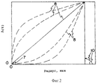
На фиг. 2 изображен график, показывающий альтернативные профили показателя преломления, имеющие острый минимум. In FIG. 2 is a graph showing alternative refractive index profiles having a sharp minimum.
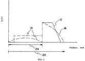
На фиг. 3 изображен график, показывающий профиль показателя преломления в виде трапецеидального кольца, расположенного на расстоянии от оси волновода, и альтернативные варианты. In FIG. 3 is a graph showing the profile of the refractive index in the form of a trapezoidal ring located at a distance from the axis of the waveguide, and alternatives.
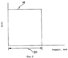
На фиг. 4 изображен вариант выполнения нового профиля показателя преломления ступенчатого типа. In FIG. 4 shows an embodiment of a new step-type refractive index profile.
Преимуществами двух рабочих окон, то есть двух диапазонов длин волн сигнала, отличающихся на несколько сотен нанометров, являются следующие:
- система может работать в одном окне до тех пор, пока требуемая скорость передачи информации не будет оправдывать использования второго рабочего окна,
- второе окно может работать как резервное для линий связи, требующих по существу безаварийной работы, и
- второе окно может использоваться в случае переполнения первого окна в системах с большой разностью между пиковой и средней потребностью в скорости передачи данных.The advantages of two working windows, that is, two ranges of signal wavelengths, differing by several hundred nanometers, are as follows:
- the system can operate in one window until the required information transfer rate justifies the use of a second working window,
- the second window can operate as a backup for communication lines requiring essentially trouble-free operation, and
- the second window can be used in case of overflow of the first window in systems with a large difference between the peak and average demand for data transfer speed.
Настоящее изобретение предлагает волноводное волокно с двойным окном, дополнительным свойством которого является то, что для него минимальны нелинейные эффекты, которые могут возникнуть в системах большой мощности, системах с уплотнением по длинам волн или в системах, включающих оптические усилители. Новые волноводные волокна согласно данной заявке имеют большую эффективную площадь в окнах как на 1300 нм, так и на 1550 нм. Первый вариант выполнения нового профиля сердцевины волновода изображен на фиг. 1. Относительный показатель преломления 1 около центральной оси мал, обычно меньше 0,20%. Уровень легирования увеличивается с радиусом, как показывает кривая 2, до достижения максимального значения Δ %. Конечная часть 4 профиля показателя преломления представляет резкий спад Δ % до нуля. Есть несколько эквивалентных профилей показателя преломления, в которых кривая 4 может быть изменена без значительного воздействия на свойства волноводного волокна. Например, кривая 4 может быть наклонена наружу, чтобы увеличить радиус примерно на микрон, или соединение кривых 4 и 2 может быть закругленным. Кроме того, могут быть выполнены небольшие дополнения к профилю показателя преломления, как показывают кривые 6, без значительного изменения свойств волноводного волокна. Таким образом, на фиг. 1 и фиг. 2 представлено семейство профилей показателя преломления, которые обеспечивают большую эффективную площадь на длине волны 1300 нм. Кривые 8 на фиг. 2 показывают несколько разновидностей нового семейства профилей показателя преломления. Кривые 10 изображают разные виды отклонений от предлагаемого профиля показателя преломления, все еще обеспечивающие требуемые свойства волноводного волокна. The present invention provides a double-window waveguide fiber, an additional property of which is that it has minimal non-linear effects that can occur in high power systems, wavelength-division multiplexing systems, or systems including optical amplifiers. New waveguide fibers according to this application have a large effective area in the windows at both 1300 nm and 1550 nm. A first embodiment of a new waveguide core profile is shown in FIG. 1. The relative
Дополнительным преимуществом профилей показателя преломления на фиг. 1 и 2 является то, что интегральный уровень легирования у них ниже по сравнению со стандартным профилем со ступенчатым изменением показателя преломления. Следовательно, затухание, которое зависит от количества легирующей примеси, в новом волноводном волокне будет меньше. An additional advantage of refractive index profiles in FIG. 1 and 2, the integral doping level is lower in comparison with the standard profile with a stepwise change in the refractive index. Therefore, the attenuation, which depends on the amount of dopant, in the new waveguide fiber will be less.
Пример. Свойства волновода с профилем, имеющим острый минимум
Для профилей показателя преломления, показанных непрерывной линией на фиг. 1, вычислены по компьютерной модели следующие характеристики: λ0 = 1298 нм; диаметр поля моды равен 10,91 мкм; Dэфф = 11,22 мкм; Aэфф = 98,9 мкм2; критическая длина волны равна 1480 нм и интегральный уровень GeO2 равен 2,58.Example. Properties of a waveguide with a profile having a sharp minimum
For the refractive index profiles shown by the solid line in FIG. 1, the following characteristics are calculated using a computer model: λ 0 = 1298 nm; the diameter of the mode field is 10.91 microns; D eff = 11.22 microns; A eff = 98.9 μm 2 ; the critical wavelength is 1480 nm and the integral level of GeO 2 is 2.58.
Отметим, что Dэфф больше диаметра поля моды и Aэфф почти на 25% больше, чем у стандартного волокна со ступенчатым изменением показателя преломления.Note that D eff is larger than the mode field diameter and A eff is almost 25% larger than that of a standard fiber with a stepwise change in the refractive index.
Для сравнения, волокно со ступенчатым изменением показателя преломления, имеющее радиус как на фиг. 1 и Δ = 0,36%, имеет следующие характеристики: λ0 = 1309 нм, диаметр поля моды равен 10,1 мкм; Dэфф = 9,97 мкм; Aэфф = 78 мкм2, критическая длина волны равна 1324 нм и интегральный уровень GeO2 равен 2,8. Эффективная площадь намного меньше и длина волны нулевой дисперсии λ0 находится в рабочем окне, что нежелательно для систем с уплотнением по длинам волн. Увеличение интегрального уровня GeO2 у стандартного ступенчатого профиля показателя преломления на 9% приведет к увеличению затухания в волноводе вследствие рэлеевского рассеяния. Как большая эффективная площадь, так и меньшее затухание у новых профилей показателя преломления волноводного волокна уменьшают нежелательные нелинейные эффекты.For comparison, a fiber with a step change in refractive index having a radius as in FIG. 1 and Δ = 0.36%, has the following characteristics: λ 0 = 1309 nm, the diameter of the mode field is 10.1 μm; D eff = 9.97 microns; A eff = 78 μm 2 , the critical wavelength is 1324 nm and the integral level of GeO 2 is 2.8. The effective area is much smaller and the wavelength of zero dispersion λ 0 is in the working window, which is undesirable for systems with wavelength division multiplexing. A 9% increase in the integral GeO 2 level of the standard step profile of the refractive index will lead to an increase in attenuation in the waveguide due to Rayleigh scattering. Both the large effective area and the smaller attenuation of new refractive index profiles of the waveguide fiber reduce undesirable nonlinear effects.
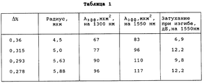
Стандартный ступенчатый профиль показателя преломления можно легко изменить для получения большой эффективной площади. Профиль характеризуется Δ ступеньки (18 на фиг. 4) и радиусом 20. В табл. 1 показано влияние изменения Δ% и изменения радиуса на эффективную площадь и устойчивость к изгибу на ряде стержней. The standard stepped refractive index profile can be easily changed to obtain a large effective area. The profile is characterized by Δ steps (18 in Fig. 4) and a radius of 20. In the table. Figure 1 shows the effect of changes in Δ% and changes in radius on the effective area and resistance to bending on a number of rods.
Существование компромиса при выборе между устойчивостью к изгибу и большей эффективной площадью очевидно. Уменьшение Δ% и увеличение радиуса обеспечивают требуемую большую эффективную площадь. Ступенчатая конструкция при Δ% около 0,3% и радиусе около 5,6 мкм обеспечивает приемлемую устойчивость к изгибу при значительном увеличении Aэфф.The existence of a compromise in choosing between bending resistance and a larger effective area is obvious. A decrease in Δ% and an increase in radius provide the required large effective area. A step design with Δ% of about 0.3% and a radius of about 5.6 microns provides acceptable bending resistance with a significant increase in A eff .
Трапецеидальный профиль показателя преломления на расстоянии от центральной оси волновода обеспечивает дополнительную гибкость конструкции профиля показателя преломления для получения приемлемой устойчивости к изгибу в сочетании с большой эффективной площадью в окнах на обеих длинах волн. The trapezoidal profile of the refractive index at a distance from the central axis of the waveguide provides additional flexibility in the design of the profile of the refractive index to obtain acceptable bending resistance in combination with a large effective area in the windows at both wavelengths.
Основная форма этого варианта выполнения нового волноводного волокна изображена на фиг. 3. Трапецеидальная фигура 12 расположена на расстоянии от центральной оси волновода. Внутренний и внешний радиусы трапецеидального участка профиля показателя преломления сердцевины обозначены 24 и 22, соответственно. Профиль показателя преломления участка сердцевины рядом с центральной осью волновода может быть по существу плоским или иметь криволинейную форму, как изображено кривыми 14. Требуемые характеристики нового волновода могут быть получены путем незначительных изменений формы трапеции, как показывает кривая 16, или подбором эквивалентных профилей показателя преломления. The basic form of this embodiment of the new waveguide fiber is shown in FIG. 3. The trapezoidal figure 12 is located at a distance from the Central axis of the waveguide. The inner and outer radii of the trapezoidal section of the core refractive index profile are designated 24 and 22, respectively. The profile of the refractive index of the core region near the central axis of the waveguide can be essentially flat or have a curved shape, as shown by
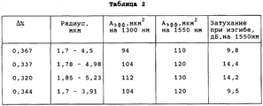
В табл. 2 приведены моделированные параметры трапецеидального варианта выполнения нового волноводного волокна. В колонке "Радиус" первая величина равна внутреннему радиусу трапеции, а вторая величина равна ее внешнему радиусу. In the table. Figure 2 shows the simulated parameters of a trapezoidal embodiment of a new waveguide fiber. In the "Radius" column, the first value is equal to the inner radius of the trapezoid, and the second value is equal to its outer radius.
Отличные характеристики показывают профили из первой и четвертой строк. Эти варианты выполнения отвечают требованиям к оптическим волноводным волокнам, которые ограничивают нелинейные эффекты и сохраняют при этом необходимую устойчивость к изгибу. The excellent characteristics are shown by profiles from the first and fourth lines. These embodiments meet the requirements for optical waveguide fibers that limit nonlinear effects and retain the necessary bending resistance.
Таблицы 1 и 2 показывают, что компьютерная модель необходима для эффективного определения профилей показателя преломления, которые отвечают заданному ряду требований. Сравнение профилей коэффициента преломления, приведенных в строках таблиц, показывает, что незначительные изменения параметров профиля могут оказывать значительное влияние на характеристики волновода. Таким образом, число комбинаций и перестановок, которые должны быть проверены, требует, чтобы компьютерное моделирование предшествало изготовлению волноводного волокна. Tables 1 and 2 show that a computer model is needed to efficiently determine refractive index profiles that meet a given set of requirements. A comparison of the refractive index profiles given in the rows of the tables shows that slight changes in the profile parameters can have a significant effect on the characteristics of the waveguide. Thus, the number of combinations and permutations that need to be verified requires that computer simulation precede the fabrication of the waveguide fiber.
Хотя приведены и описаны конкретные варианты выполнения изобретения, изобретение ограничено только формулой изобретения. Although specific embodiments of the invention are shown and described, the invention is limited only by the claims.
Claims (10)
Applications Claiming Priority (2)
| Application Number | Priority Date | Filing Date | Title |
|---|---|---|---|
| US08/573,472 | 1995-12-15 | ||
| US08/573,472 US5715346A (en) | 1995-12-15 | 1995-12-15 | Large effective area single mode optical waveguide |
Publications (2)
| Publication Number | Publication Date |
|---|---|
| RU96123578A RU96123578A (en) | 1999-02-10 |
| RU2166782C2 true RU2166782C2 (en) | 2001-05-10 |
Family
ID=24292129
Family Applications (1)
| Application Number | Title | Priority Date | Filing Date |
|---|---|---|---|
| RU96123578/28A RU2166782C2 (en) | 1995-12-15 | 1996-12-14 | Single-mode optical waveguide with large effective area ( versions ) |
Country Status (13)
| Country | Link |
|---|---|
| US (1) | US5715346A (en) |
| EP (2) | EP0779524B1 (en) |
| JP (1) | JP3223474B2 (en) |
| KR (1) | KR970042359A (en) |
| CN (1) | CN1113256C (en) |
| AU (1) | AU721088B2 (en) |
| BR (1) | BR9605852A (en) |
| CA (1) | CA2192425A1 (en) |
| DE (1) | DE69620558T2 (en) |
| DK (1) | DK0779524T3 (en) |
| RU (1) | RU2166782C2 (en) |
| TW (1) | TW316951B (en) |
| UA (1) | UA39137C2 (en) |
Families Citing this family (50)
| Publication number | Priority date | Publication date | Assignee | Title |
|---|---|---|---|---|
| CN1114114C (en) * | 1997-10-29 | 2003-07-09 | 康宁股份有限公司 | Waveguide profile for large effective area |
| US6031956A (en) * | 1997-11-17 | 2000-02-29 | Corning Incorporated | High performance single mode waveguide |
| US5905838A (en) * | 1998-02-18 | 1999-05-18 | Lucent Technologies Inc. | Dual window WDM optical fiber communication |
| FR2782390A1 (en) * | 1998-08-13 | 2000-02-18 | Alsthom Cge Alcatel | Single mode fibre optic cable index profiling construction; has V-shaped core profile index with outer core index rising above constant level outer sleeve index |
| US6212322B1 (en) * | 1998-09-11 | 2001-04-03 | Corning Incorporated | Positive dispersion low dispersion slope fiber |
| US6337942B1 (en) | 1998-12-17 | 2002-01-08 | Sumitomo Electric Industries, Ltd. | Optical fiber |
| WO2000036443A1 (en) * | 1998-12-17 | 2000-06-22 | Sumitomo Electric Industries, Ltd. | Optical fiber |
| WO2000037977A1 (en) * | 1998-12-18 | 2000-06-29 | Pirelli Cavi E Sistemi S.P.A. | Optical fiber for metropolitan and access network systems |
| FR2790106B1 (en) * | 1999-02-18 | 2001-05-04 | Cit Alcatel | BROADBAND INDEX JUMP FIBER |
| FR2790108B1 (en) * | 1999-02-18 | 2001-05-04 | Cit Alcatel | OPTICAL FIBER WITH LARGE EFFECTIVE SURFACE AND HIGH CHROMATIC DISPERSION |
| FR2790105B1 (en) * | 1999-02-18 | 2003-07-04 | Cit Alcatel | FIBER OPTIC TRANSMISSION SYSTEM, LINE AND METHOD |
| CA2334888A1 (en) * | 1999-04-13 | 2000-10-19 | Sumitomo Electric Industries, Ltd. | Optical fiber and optical communication system comprising the same |
| CA2340948A1 (en) * | 1999-06-25 | 2001-01-04 | The Furukawa Electric Co., Ltd. | Dispersion compensation optical fiber and optical transmission line comprising the dispersion compensation optical fiber |
| US6785453B1 (en) | 1999-07-12 | 2004-08-31 | Fujikura Ltd. | Dispersion shifted optical fiber |
| US6694079B1 (en) | 1999-07-27 | 2004-02-17 | Fujikura Ltd. | Disperson-shifted optical fiber employing dual shape core profile |
| WO2001014917A1 (en) | 1999-08-20 | 2001-03-01 | The Furukawa Electric Co., Ltd. | Optical fiber and optical transmission line including the same |
| WO2001018575A1 (en) * | 1999-09-09 | 2001-03-15 | Fujikura Ltd. | Dispersion shift optical fiber |
| US6424778B1 (en) | 1999-09-29 | 2002-07-23 | Corning Incorporated | Optical fiber with large effective area and low dispersion slope for submarine applications |
| WO2001038911A1 (en) | 1999-11-22 | 2001-05-31 | Corning Incorporated | Dispersion shifted large effective area waveguide fiber |
| KR20030051707A (en) | 2000-10-11 | 2003-06-25 | 코닝 인코포레이티드 | Single mode optical waveguide fiber with reduced dispersion |
| JP2002202428A (en) * | 2000-10-31 | 2002-07-19 | Sumitomo Electric Ind Ltd | Optical fiber |
| US6611647B2 (en) | 2000-12-12 | 2003-08-26 | Corning Incorporated | Large effective area optical fiber |
| JP2002208676A (en) | 2001-01-10 | 2002-07-26 | Mitsubishi Electric Corp | Semiconductor device, manufacturing and designing method therefor |
| JP3845260B2 (en) * | 2001-02-16 | 2006-11-15 | 古河電気工業株式会社 | Optical fiber and optical transmission line |
| US6516124B2 (en) * | 2001-03-02 | 2003-02-04 | Optical Power Systems Incorporated | Fiber for enhanced energy absorption |
| US7043125B2 (en) | 2001-07-30 | 2006-05-09 | Corning Incorporated | Optical waveguide fiber for local access |
| EP1444538A2 (en) * | 2001-11-15 | 2004-08-11 | Corning Incorporated | High capacity optical waveguide fiber |
| US6801699B1 (en) | 2001-11-15 | 2004-10-05 | Corning Incorporated | High capacity optical waveguide fiber |
| JPWO2003104886A1 (en) * | 2002-06-11 | 2005-10-13 | 古河電気工業株式会社 | Wavelength division multiplexing optical regeneration system and wavelength division multiplexing optical regeneration method |
| JP4073806B2 (en) * | 2002-08-09 | 2008-04-09 | 株式会社フジクラ | Optical fiber and optical transmission line using the optical fiber |
| CN100507621C (en) | 2003-04-17 | 2009-07-01 | 日本电信电话株式会社 | Hole-assisted single mode optical fiber |
| US6904218B2 (en) | 2003-05-12 | 2005-06-07 | Fitel U.S.A. Corporation | Super-large-effective-area (SLA) optical fiber and communication system incorporating the same |
| JP4451696B2 (en) | 2004-03-30 | 2010-04-14 | 富士通株式会社 | Device for canceling wavelength dependence of nonlinear coefficient of microstructured fiber |
| JP2006154707A (en) * | 2004-10-29 | 2006-06-15 | Shin Etsu Chem Co Ltd | Optical fiber |
| CN102185238B (en) * | 2011-04-01 | 2012-05-23 | 北京交通大学 | Large-effective-area single mode optical fiber amplifier based on change of refractive index distribution of cladding |
| CN102255228B (en) * | 2011-05-09 | 2012-05-30 | 北京交通大学 | Optical fiber amplifier having light collecting layer structure |
| CN102183813B (en) * | 2011-05-09 | 2012-05-30 | 北京交通大学 | Optical fiber structure with spotlighting layer |
| CN102222855B (en) * | 2011-05-09 | 2012-05-30 | 北京交通大学 | Fiber laser with spotlighting layer structure |
| EP2754524B1 (en) | 2013-01-15 | 2015-11-25 | Corning Laser Technologies GmbH | Method of and apparatus for laser based processing of flat substrates being wafer or glass element using a laser beam line |
| EP2781296B1 (en) | 2013-03-21 | 2020-10-21 | Corning Laser Technologies GmbH | Device and method for cutting out contours from flat substrates using a laser |
| US9517963B2 (en) | 2013-12-17 | 2016-12-13 | Corning Incorporated | Method for rapid laser drilling of holes in glass and products made therefrom |
| US11556039B2 (en) | 2013-12-17 | 2023-01-17 | Corning Incorporated | Electrochromic coated glass articles and methods for laser processing the same |
| CN106687419A (en) | 2014-07-08 | 2017-05-17 | 康宁股份有限公司 | Methods and apparatuses for laser processing materials |
| EP3169477B1 (en) | 2014-07-14 | 2020-01-29 | Corning Incorporated | System for and method of processing transparent materials using laser beam focal lines adjustable in length and diameter |
| KR102546692B1 (en) | 2015-03-24 | 2023-06-22 | 코닝 인코포레이티드 | Laser Cutting and Processing of Display Glass Compositions |
| WO2017011296A1 (en) | 2015-07-10 | 2017-01-19 | Corning Incorporated | Methods of continuous fabrication of holes in flexible substrate sheets and products relating to the same |
| US9995873B2 (en) | 2016-07-29 | 2018-06-12 | Corning Incorporated | Single-mode large effective area optical fibers |
| KR102078294B1 (en) | 2016-09-30 | 2020-02-17 | 코닝 인코포레이티드 | Apparatus and method for laser machining transparent workpieces using non-axisymmetric beam spots |
| EP3848333A1 (en) | 2016-10-24 | 2021-07-14 | Corning Incorporated | Substrate processing station for laser-based machining of sheet-like glass substrates |
| CN112099130B (en) * | 2020-09-25 | 2021-07-13 | 东北大学 | Slope-type refractive index distribution multi-core optical fiber with low crosstalk between cores |
Family Cites Families (11)
| Publication number | Priority date | Publication date | Assignee | Title |
|---|---|---|---|---|
| JPS583205B2 (en) * | 1979-10-08 | 1983-01-20 | 日本電信電話株式会社 | Ultra-wideband single mode optical fiber |
| US4473273A (en) * | 1981-09-04 | 1984-09-25 | Trw Inc. | High bandwidth fiber and method of forming the same by preform rotation during drawing |
| US4715679A (en) * | 1981-12-07 | 1987-12-29 | Corning Glass Works | Low dispersion, low-loss single-mode optical waveguide |
| JPS62165608A (en) * | 1986-01-17 | 1987-07-22 | Fujitsu Ltd | Single mode optical fiber |
| JPH0695167B2 (en) * | 1986-03-04 | 1994-11-24 | 富士通株式会社 | Wide wavelength range low dispersion single mode fiber |
| DE3812140A1 (en) * | 1988-04-12 | 1989-11-02 | Schott Glaswerke | MONOMODE LIGHT FIBER |
| JPH03242343A (en) * | 1990-02-19 | 1991-10-29 | Shin Etsu Chem Co Ltd | Production of glass preform for optical fiber |
| JP3132729B2 (en) * | 1990-02-23 | 2001-02-05 | 住友電気工業株式会社 | Broadband high NA optical fiber |
| US5278931A (en) * | 1992-12-31 | 1994-01-11 | Corning Incorporated | Low bend loss singlemode optical waveguide fiber |
| US5559921A (en) * | 1994-06-24 | 1996-09-24 | Sumitomo Electric Industries, Ltd. | Single mode optical fiber |
| US5553185A (en) * | 1994-12-27 | 1996-09-03 | Corning Incorporated | Controlled dispersion optical waveguide |
-
1995
- 1995-12-15 US US08/573,472 patent/US5715346A/en not_active Expired - Lifetime
-
1996
- 1996-12-04 BR BR9605852A patent/BR9605852A/en not_active IP Right Cessation
- 1996-12-05 AU AU74179/96A patent/AU721088B2/en not_active Ceased
- 1996-12-05 UA UA96124554A patent/UA39137C2/en unknown
- 1996-12-09 CA CA002192425A patent/CA2192425A1/en not_active Abandoned
- 1996-12-11 DE DE69620558T patent/DE69620558T2/en not_active Expired - Fee Related
- 1996-12-11 EP EP96119852A patent/EP0779524B1/en not_active Expired - Lifetime
- 1996-12-11 DK DK96119852T patent/DK0779524T3/en active
- 1996-12-11 EP EP01120120A patent/EP1160595A3/en not_active Withdrawn
- 1996-12-12 TW TW085115503A patent/TW316951B/zh active
- 1996-12-13 CN CN96123232A patent/CN1113256C/en not_active Expired - Fee Related
- 1996-12-14 KR KR1019960065874A patent/KR970042359A/en active IP Right Grant
- 1996-12-14 RU RU96123578/28A patent/RU2166782C2/en active
- 1996-12-16 JP JP33552296A patent/JP3223474B2/en not_active Expired - Fee Related
Also Published As
| Publication number | Publication date |
|---|---|
| EP0779524B1 (en) | 2002-04-10 |
| CA2192425A1 (en) | 1997-06-16 |
| JP3223474B2 (en) | 2001-10-29 |
| AU7417996A (en) | 1997-06-19 |
| KR970042359A (en) | 1997-07-24 |
| US5715346A (en) | 1998-02-03 |
| BR9605852A (en) | 1998-08-25 |
| DE69620558D1 (en) | 2002-05-16 |
| CN1160214A (en) | 1997-09-24 |
| AU721088B2 (en) | 2000-06-22 |
| EP0779524A2 (en) | 1997-06-18 |
| EP1160595A2 (en) | 2001-12-05 |
| EP1160595A3 (en) | 2001-12-12 |
| CN1113256C (en) | 2003-07-02 |
| DK0779524T3 (en) | 2002-07-29 |
| TW316951B (en) | 1997-10-01 |
| JPH09274118A (en) | 1997-10-21 |
| DE69620558T2 (en) | 2002-10-10 |
| UA39137C2 (en) | 2001-06-15 |
| EP0779524A3 (en) | 1998-04-29 |
Similar Documents
| Publication | Publication Date | Title |
|---|---|---|
| RU2166782C2 (en) | Single-mode optical waveguide with large effective area ( versions ) | |
| EP0260795B1 (en) | Optical fiber | |
| KR100636332B1 (en) | Optical fiber for extended wavelength band | |
| KR100353755B1 (en) | Dispersion flat optical fiber | |
| US7558461B2 (en) | High SBS threshold optical fiber with aluminum dopant | |
| US6363196B1 (en) | Single mode dispersion-shifted optical fiber with external refractive index ring | |
| KR100694365B1 (en) | Positive dispersion low dispersion slope fiber | |
| AU748054B2 (en) | Waveguide profile for large effective area | |
| US20040197063A1 (en) | Dispersion shifted fiber having low dispersion slope | |
| JP2004500603A (en) | Dispersion gradient compensated optical waveguide fiber | |
| US6317552B1 (en) | Dispersion managed optical waveguide fiber | |
| KR100571618B1 (en) | High Performance Single Mode Waveguide | |
| US6510268B1 (en) | Optical fiber for compensating the chromatic dispersion of an optical fiber having positive chromatic dispersion | |
| JP2005520200A (en) | Dispersion compensating optical fiber and optical transmission line using the same | |
| JP2004520607A (en) | Low dispersion single mode optical fiber | |
| CN114153021A (en) | Low dispersion slope large effective area non-zero dispersion displacement optical fiber | |
| WO2004034109A1 (en) | Bragg grating optical fiber | |
| KR20010053516A (en) | Single mode optical waveguide | |
| RU2172505C2 (en) | Single-mode optical waveguide with large effective area | |
| AU740523B2 (en) | Large effective area single mode optical waveguide |