JP2004520607A - Low dispersion single mode optical fiber - Google Patents
Low dispersion single mode optical fiber Download PDFInfo
- Publication number
- JP2004520607A JP2004520607A JP2002534882A JP2002534882A JP2004520607A JP 2004520607 A JP2004520607 A JP 2004520607A JP 2002534882 A JP2002534882 A JP 2002534882A JP 2002534882 A JP2002534882 A JP 2002534882A JP 2004520607 A JP2004520607 A JP 2004520607A
- Authority
- JP
- Japan
- Prior art keywords
- refractive index
- radius
- segment
- range
- core
- Prior art date
- Legal status (The legal status is an assumption and is not a legal conclusion. Google has not performed a legal analysis and makes no representation as to the accuracy of the status listed.)
- Pending
Links
Images


Classifications
-
- G—PHYSICS
- G02—OPTICS
- G02B—OPTICAL ELEMENTS, SYSTEMS OR APPARATUS
- G02B6/00—Light guides; Structural details of arrangements comprising light guides and other optical elements, e.g. couplings
- G02B6/02—Optical fibres with cladding with or without a coating
- G02B6/036—Optical fibres with cladding with or without a coating core or cladding comprising multiple layers
- G02B6/03616—Optical fibres characterised both by the number of different refractive index layers around the central core segment, i.e. around the innermost high index core layer, and their relative refractive index difference
- G02B6/03638—Optical fibres characterised both by the number of different refractive index layers around the central core segment, i.e. around the innermost high index core layer, and their relative refractive index difference having 3 layers only
- G02B6/03644—Optical fibres characterised both by the number of different refractive index layers around the central core segment, i.e. around the innermost high index core layer, and their relative refractive index difference having 3 layers only arranged - + -
-
- G—PHYSICS
- G02—OPTICS
- G02B—OPTICAL ELEMENTS, SYSTEMS OR APPARATUS
- G02B6/00—Light guides; Structural details of arrangements comprising light guides and other optical elements, e.g. couplings
- G02B6/02—Optical fibres with cladding with or without a coating
- G02B6/02004—Optical fibres with cladding with or without a coating characterised by the core effective area or mode field radius
- G02B6/02009—Large effective area or mode field radius, e.g. to reduce nonlinear effects in single mode fibres
- G02B6/02014—Effective area greater than 60 square microns in the C band, i.e. 1530-1565 nm
-
- G—PHYSICS
- G02—OPTICS
- G02B—OPTICAL ELEMENTS, SYSTEMS OR APPARATUS
- G02B6/00—Light guides; Structural details of arrangements comprising light guides and other optical elements, e.g. couplings
- G02B6/02—Optical fibres with cladding with or without a coating
- G02B6/02214—Optical fibres with cladding with or without a coating tailored to obtain the desired dispersion, e.g. dispersion shifted, dispersion flattened
- G02B6/02219—Characterised by the wavelength dispersion properties in the silica low loss window around 1550 nm, i.e. S, C, L and U bands from 1460-1675 nm
- G02B6/02228—Dispersion flattened fibres, i.e. having a low dispersion variation over an extended wavelength range
- G02B6/02238—Low dispersion slope fibres
- G02B6/02242—Low dispersion slope fibres having a dispersion slope <0.06 ps/km/nm2
-
- G—PHYSICS
- G02—OPTICS
- G02B—OPTICAL ELEMENTS, SYSTEMS OR APPARATUS
- G02B6/00—Light guides; Structural details of arrangements comprising light guides and other optical elements, e.g. couplings
- G02B6/02—Optical fibres with cladding with or without a coating
- G02B6/02214—Optical fibres with cladding with or without a coating tailored to obtain the desired dispersion, e.g. dispersion shifted, dispersion flattened
- G02B6/02219—Characterised by the wavelength dispersion properties in the silica low loss window around 1550 nm, i.e. S, C, L and U bands from 1460-1675 nm
- G02B6/02266—Positive dispersion fibres at 1550 nm
-
- G—PHYSICS
- G02—OPTICS
- G02B—OPTICAL ELEMENTS, SYSTEMS OR APPARATUS
- G02B6/00—Light guides; Structural details of arrangements comprising light guides and other optical elements, e.g. couplings
- G02B6/02—Optical fibres with cladding with or without a coating
- G02B6/036—Optical fibres with cladding with or without a coating core or cladding comprising multiple layers
- G02B6/03605—Highest refractive index not on central axis
- G02B6/03611—Highest index adjacent to central axis region, e.g. annular core, coaxial ring, centreline depression affecting waveguiding
-
- G—PHYSICS
- G02—OPTICS
- G02B—OPTICAL ELEMENTS, SYSTEMS OR APPARATUS
- G02B6/00—Light guides; Structural details of arrangements comprising light guides and other optical elements, e.g. couplings
- G02B6/02—Optical fibres with cladding with or without a coating
- G02B6/028—Optical fibres with cladding with or without a coating with core or cladding having graded refractive index
- G02B6/0281—Graded index region forming part of the central core segment, e.g. alpha profile, triangular, trapezoidal core
Abstract
相対的に大なる有効断面積と低い分散を有するシングルモード光導波路ファイバは、それぞれ半径、相対屈折率分布及び相対屈折率パーセントを有する少なくとも2つのセグメントを有するセグメントコアを含む。この導波路ファイバは、相対屈折率を有し、前記コアに接し且つこれを包囲するクラッド層を含む。前記屈折率分布は、約1550nmの波長で約11ps/nm−kmから約14ps/nm−kmの範囲内の全分散、約1550nmの波長で約0.045ps/nm2−kmから約0.055ps/nm2−kmの範囲内の全分散スロープを与える。屈折率分布は、更に、約60μm2以上の有効断面積、及び、約1550nmの波長で0.22dB/km以下の減衰を与える。A single mode optical waveguide fiber having a relatively large effective area and low dispersion includes a segment core having at least two segments each having a radius, a relative refractive index distribution, and a relative refractive index percent. The waveguide fiber has a relative refractive index and includes a cladding layer in contact with and surrounding the core. The refractive index distribution has a total dispersion in the range of about 11 ps / nm-km to about 14 ps / nm-km at a wavelength of about 1550 nm, and about 0.045 ps / nm 2 -km to about 0.055 ps at a wavelength of about 1550 nm. / Nm2-km gives the total dispersion slope. The refractive index profile also provides an effective area of about 60 μm 2 or greater and an attenuation of 0.22 dB / km or less at a wavelength of about 1550 nm.
Description
本出願は、2000年10月11日に出願された米国仮特許出願第60/239,563号についての利益及び優先権を請求する。
【0001】
【発明の属する技術分野】
本発明は、通信システムに使用されるシングルモード光導波路ファイバに関し、詳細には、非線形分散の影響を減じて、大なる有効断面積と低減衰とを具備した導波路ファイバに関する。
【0002】
【従来の技術】
波長分割多重化技術がメトロポリタンエリアネットワークで使用される通信システムにおいて一般的に必要とされている。この種のシステムのデータレートは高く、バンド幅の需要が大容量伝送能力を提供するために大である。メトロポリタンエリアネットワーク内で使用される基本ファイバであったシングルモード光導波路ファイバでは、安価で製造容易な直接変調型DFBレーザ(分散帰還型レーザ)を使用することができず、重大な障害を生じている。直接変調DFBレーザを使用することにより、その大きな線形分散故に非線形分散効果と同程度の信号品質の劣化が生じてしまう。故に、より高価な外部調整された送信機又は電界吸収型DFBレーザを使用しなければならないのである。
【0003】
多重伝送のために適切な導波路ファイバを与えるためには、全分散がゼロではないが、小さくなされる必要があって、且つ、動作波長窓に亘って低い傾斜(スロープ)を有していなければならない。動作波長バンドに亘って全分散をゼロではなく維持することで、四光波混合による非線形分散効果を制限できる。
分散を減じることを目的に導波路ファイバを設計するときに、他のいくつかの非線形光学効果を考慮しなければならないが、更に、多重化技術を利用する際の直接変調型DFBレーザとの使用互換性についても考慮しなければならない。これら非線形光学効果は、四光波混合、自己位相変調、相互位相変調及び非線形散乱を含む。
【0004】
通常、大なる有効断面積(Aeff)を有する光導波路ファイバは、多重化技術を利用したシステムの信号の劣化を生じさせる自己位相変調、四光波混合、相互位相変調及び非線形散乱プロセスを含む非線形光学効果を減じる。非線形光学効果を制限すると共に、セグメントコアを有する導波路ファイバは一般に大なる有効断面積を提供することができる。
【0005】
これらの非線形効果の数学的な記述は、P/Aeffの比を含む。ここで、Pは光パワーである。例えば、非線形光学効果は、式exp [P×Leff/Aeff]を含んで記載され得る。ここで、Leffは実効長である。故に、Aeffの増加は、光信号の劣化に対する非線形性の寄与の減少を生じさせる。
情報容量をより大きく且つ光源(例えば直接的に調整されたDFBレーザ)のコストを減少させるための業界の要求がシングルモード光導波路ファイバ屈折率分布デザインの再評価をもたらせた。この再評価の焦点は、以下のような光導波路を提供することである。すなわち、
−上記した如き非線形効果を減じること、
−規格のシングルモード光ファイバよりも低い分散を有すること、
−低ピーク減衰(LWP)であって全バンド波長分割多重アプリケーションに使用され得ること、
−1310nmシステムにも互換性を有すること、
−例えば、高強度、優れた疲労抵抗性及び曲げ抵抗性などの所望の導波路特性を有すること、である。
【0006】
低コストであることに加え、柔軟性の観点から製造が比較的容易でありながら分散の管理が可能な導波路デザインが好ましい。本願明細書において記載されているデザインは、導波路分散が全分散を正と負の値の間で交互に導波路ファイバ長に沿って変化する分散マネージメント手法において非常に適している。
本願明細書に完全に記載されているかの如く、引用することで本願中に取り入れられるバガバチュラ(Bhagavatula)氏の米国特許第4,715,679号は、導波路ファイバデザインの柔軟性を提供するための明確な分布を有するコアセグメントによって導波路ファイバコアに構成を付加する概念を開示している。セグメントコア概念は、例えば本願明細書において記載されている如き導波路ファイバ特性の非凡な組合せを達成するために使用され得る。
【0007】
【発明の概要】
本発明は、相対的に大なる有効断面積を有する相対的に低い全分散(導波路分散及び材料分散の合計)の利益を提供するシングルモード光導波路ファイバに対する要求を満たす。
本発明は、セグメントコアを含むシングルモード光導波路ファイバに関する。セグメントの各々は、屈折率分布、相対屈折率パーセント及び内部半径及び外部半径によって記載される。光導波路ファイバは、コアを包囲するとともにこれに接するとともに屈折率分布を有するクラッド層を更に含む。
【0008】
好適な実施例において、屈折率分布は、約1550nmの波長で約11ps/nm−kmから約14ps/nm−kmの範囲内の全分散、約1550nmの波長で約0.045ps/nm2−kmから約0.055ps/nm2−kmの範囲内の全分散スロープ、60μm2以上の有効断面積、約1550nmの波長で0.22dB/km以下の減衰を与えるように選択されている。
【0009】
【発明の実施の形態】
本発明の追加の特徴及び利点は、以下の詳細な説明に記載され、当業者であれば詳細な説明から明らかになるであろう。また、特許請求の範囲及び添付の図面とともに、以下の詳細な説明に記載される本発明を実践することによって認識されるであろう。
【0010】
前述の説明は、本発明の典型例にすぎず、特許請求の範囲によって定義される本発明の性質及び特徴の理解のための概要を与えることを意図していると理解されるであろう。添付の図面は、本発明の更なる理解を提供するために含まれて、取り入れられて本願明細書の一部を構成する。図面は、本発明のさまざまな特徴及び実施例を示し、発明の詳細な説明と共に本発明の原理及び動作の説明を与える。
(定義)
以下の定義は、従来技術においても共通して使用される。
−コアのセグメントの半径は、セグメントを構成する材料の屈折率の区間で定義される。特定のセグメントは、起点及び終点屈折率ポイントを有する。中央セグメントの起点は、中心線にあるので中央セグメントはゼロの内側半径を有する。中央セグメントの外側半径は、導波路中心線から中央セグメントの屈折率の終点まで線引きされる半径である。中心線から離れた位置に起点を有するセグメントでは、導波路中心線からその起点屈折率ポイント位置までの半径を当該セグメントの内側半径とする。同様に、導波路中心線からセグメントの終点屈折率ポイント位置までの半径がセグメントの外側半径である。セグメントの半径は、いくつかの方法で便宜的に定義され得る。本願において、半径は、図及び以下の記載に従って定義される。
−屈折率分布を記載するために使用されるセグメント半径及び屈折率の定義は、本発明を制限するものではない。モデル計算を実行する際には一貫した用語が使用される必要があるので、本願明細書において定義を与える。以下の表に記載されたモデル計算は、図において参照符を付されるとともに詳細な説明において記載された幾何学図形の定義を使用して行われる。
−有効断面積は一般的に以下の如く定義される。
【0011】
【数1】

−モードフィールド直径Dmfは、PetermanII法を用いて計測された。ここで、
2w=Dmf
【0012】
【数2】
−本願明細書において使用されるセグメントΔ%の屈折率は、以下の式で定義される。
【0013】
【数3】
−屈折率分布又は分布の術語は、コアの選択されたセグメントに亘るΔ%若しくは屈折率と半径との間の関係である。
−α分布の術語は、以下の式によって表され得る屈折率分布を参照する。
【0014】
n(r)=no(1−Δ[r/a]α)
ここで、rはコア半径、Δは上記した定義、aは分布セグメントの終点位置である。α分布の始点位置でのrの値は分布セグメントの起点位置と一致するように選択される。αは分布形状を定義する指数である。他の屈折率分布はステップ屈折率、台形屈折率及び丸めステップ屈折率を含む。ここで、「丸め」は、通常、急激に屈折率が変化する領域にドーパントを拡散させることによる。
−全分散は、導波路分散及び材料分散の代数和として定義される。全分散は、従来技術ではクロマチック分散とも称する。全分散の単位は、ps/nm−kmである。
−屈折率分布は、形状の異なる関連した実効屈折率分布を一般的に有する。導波路特性を変えることなく、その関連した屈折率分布のために、実効屈折率分布は置換され得る。
−導波路ファイバの曲げ抵抗性は、定められたテスト条件の下で誘発された減衰として表される。本願明細書において参照される曲げ試験は、曲げに対する導波路ファイバの相対的な抵抗性を比較するために使用されるピン配列曲げ試験である。まず、この試験を実行するために、減衰損失は実質的に曲げ損失を誘起されていない導波路ファイバで測定される。続いて、この導波路ファイバは、ピン配列の間を蛇行して織り込まれて再び減衰が測定される。曲げによって誘起される損失は、2回測定された減衰値における差である。ピン配列は、一列に配置された一組10本の円筒ピンであって、平面上に固定された位置を維持している。ピン間隔は、中心と中心との間で5mmである。ピン直径は、0.67mmである。この試験の間、蛇行して織り込まれた導波路ファイバを、ピンとファイバとの間の接触するピン表面の部分に適合させるために充分な張力が印加される。
【0015】
本願中に記載され、開示されるセグメントコア光導波路は、一般にセグメント化されたコアを有する。セグメントの各々は、屈折率分布、相対屈折率パーセントΔi%及び外側半径ri(図5)によって記載される。(セグメントの内側半径は、中央セグメントの場合には中心線であって、その他の場合はその前のセグメントの外側半径である。ここで、セグメントの数え方は、導波路の中心線から外側へ向かって数える。)r及びΔの添え字iは、特定のセグメントを参照する。セグメントは、導波路長軸中心線を含む最も奥のセグメントから初めて、1からnの番号が付される。ncの屈折率を有するクラッド層がコアを包囲している。
【0016】
コアの各々のセグメントの半径、相対屈折率パーセント及び屈折率分布は、1550nmで0.22dB/km以下の減衰、約1270nmから約1350nmの範囲内にあるゼロ分散波長、1550nmで約11.0ps/nm−kmから約14.0ps/nm−kmの範囲内にある全分散、1550nmで約0.045ps/nm2−kmから約0.055ps/nm2−kmの範囲内にある全分散スロープ、1550nmで60μm2よりも大なる有効断面積、ケーブル化された状態で約1280nm未満のファイバのカットオフ波長、及び、約0.1ps/(km)1/2から約0.25ps/(km)1/2の範囲内の偏光モード分散、を与えるように選択される。本願の新規なセグメントコアデザインは、上記した要求される特性カタログを呈する。
【0017】
コア屈折率分布の一般的な表現は、導波路半径に対する相対屈折率パーセントを示す図1において示される。図1は単一のセグメントコアのみを図示しているが、機能的な要求は単一のセグメントよりも数多くのセグメントを有するコアを形成することによって達成されてもよいと理解される。しかしながら、より少ないセグメントを有する実施例の方が一般的には製造がより容易であるが故に好まれる。
【0018】
この新規な導波路ファイバの屈折率分布の構成上の特徴は、正のΔ%を有するコアセグメント10によって示される。図示した導波路ファイバコアの中央セグメント10は、α形状分布を有する。この屈折率分布は、要求される導波路ファイバ特性を与えるコアデザインとなるように調整され得る。
図2は、新規な導波路ファイバコアデザインの他のシングルセグメントバリエーションを示している。このデザインにおいて、当該新規な導波路ファイバはα形状分布を有する中央コアセグメント20を含む。
【0019】
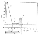
図3は、新規な導波路ファイバコアデザインの3セグメントコアバリエーションを示している。このデザインにおいて、新規な導波路ファイバのコアは、中央セグメント30と、中央セグメント30と隣接してこれを包囲する第1環状セグメント32と、第1環状セグメント32と隣接してこれを包囲する第2環状セグメント34と、を含む。中央セグメント30は、α形状分布を有する。また、第1環状セグメント32及び第2環状セグメント34は、それぞれステップ形状分布を有する。
【0020】
図4は、新規な導波路ファイバコアデザインの他の3セグメントコアバリエーションを示す。この場合、コアは中央セグメント40、第1環状セグメント42及び第2環状セグメント44を有する。中央セグメント40は、α形状分布を有する。また、第1環状セグメント42及び第2環状セグメント44は、それぞれステップ形状分布を有する。以下の実施例において議論される如く、各々の上記実施例と関連する特性は互いに変化する。
【0021】
図1、2、3及び4のそれぞれの線12、22、36及び46は、セグメントのΔ%の特性を算出するために使用されるクラッドの屈折率を表していることに注意すべきである。更に、中心線屈折率低下領域14、24、38及び48と同様に、図1、2、3及び4の分布の角の丸めは、導波路ファイバの製造工程の中でドーパントを拡散させることで達成し得る。例えば、ドーピングステップでこの種の拡散を補償し得るが、必ずしも必要条件ではない。コンピュータモデルは、分布の「丸め」を考慮して調整され得る。このような補償は、「丸め」が計算されたファイバ特性において大きな変化を生じさせる場合になされる。
(実施例1)
図1は、単一の中央セグメント10と内側クラッド12とを有する新規な導波路コアの実施例である。中央コア又は第1セグメント10は、約0.66%の相対屈折率Δ1、及び、約4.7μmの外側半径(r1)50(図5)を有する。中央セグメント10の外側半径(r1)は、内側クラッド12の内側半径でもある。故に、半径r1は、中央セグメント10及び内側クラッド12の交差位置である。この場合、交差位置は、中央セグメント10の屈折率分布から外挿して垂下した線16と、屈折率分布の最も負の位置を通る軸について定義された水平軸18(図示された実施例では、0%である)との交点として定義される。
【0022】
コンピュータモデルを使用して算出された図1の導波路ファイバの特性が表1に与えられる。
【0023】
【表1】
(実施例2)
中央セグメント20を有する新規な導波路の他の実施例が図2に示される。この実施例において、中央セグメント20は、約0.57の正の相対屈折率Δ1%を有する。第2の実施例の半径は、実施例1に記載される表記法を使用して算出される。中央セグメント20の半径(r1)60は、約4.2μmである。
【0024】
表2は、図2の屈折率分布の算出された特性を記載する。
【0025】
【表2】
(実施例3)
以下の表は、所望とする導波路特性の目標値を生じる単一のセグメントコア導波路の屈折率分布の他の実施例を含む。
【0026】
【表3】
図3は、3つのセグメント30、32及び34及び内側クラッド36を有する新規な導波路コアの実施例である。中央コア、すなわち第1セグメント30は、約0.66%の相対屈折率Δ1及び約4.43μmの外側半径(r1)70を有する。1番目の環状セグメント、すなわち第2セグメント32は、約0.025%の相対屈折率Δ2%を有する。中央セグメント30の外側半径(r1)70は、第1環状セグメント32の内側半径でもある。この表記法が、他の実施例及び対応する図の全てにおいて絶えず使用される。すなわち、外側半径(r1)70は、中央セグメント及び第1環状セグメントの交差位置である。この場合、交差位置は、中央セグメント30の屈折率分布から外挿して垂下した線31と、屈折率分布の最も負の位置を通る軸について定義された水平軸33(図示された実施例では、0%である)との交点として定義される。
【0027】
第1環状セグメント32の外側半径(r2)72は約9.635μmであって、ファイバ中心線から第2環状セグメント34の上昇部分の半値最大相対屈折率位置から垂下した縦線までを測定する。半値最大点は、クラッド層、すなわち参照としてΔ%=0を使用して決定される。例えば、図3において、第2環状セグメントは約0.128%の相対屈折率Δ3 %を有する。すなわち、クラッド層のΔ%=0と比較すると、その絶対値は約0.128%である。破線の縦線35は、0.064%位置から伸長しており、Δ3%の絶対値の半分である。第2環状セグメントの中心半径74は約10.4μmである。その一方で、第2環状セグメントの外側半径(r3)76は約11.165μmである。本願明細書において開示され且つ記載されている分布の最後のセグメントは、中心半径(中心線からセグメント分布の幾何学的中心までの半径)及び幅(相対屈折率分布の半値絶対値の間の距離として定義される)に関して定義された位置を有する。本出願の全体に亘って、セグメント幅のこの定義が維持される。第2環状セグメント34の幅37は、約1.53μmである。内側クラッドの相対屈折率は、0%である。
【0028】
コンピュータモデルを使用して算出された図3の導波路ファイバの特性が表4に与えられる。
【0029】
【表4】
(実施例5)
中央セグメント40、2番目のセグメントすなわち第1環状セグメント42、及び、3番目のセグメントすなわち第2環状セグメントを含む3セグメントを有する新規な導波路の他の実施例が図4に図示される。この例では、中央セグメント40は約0.66%の相対屈折率を有し、第1環状セグメント42は約0.025%の相対屈折率を有し、及び、第2環状セグメント44は約0.212%の相対屈折率を有する。内側クラッド46は、0%の相対屈折率を有する。
第2実施例の半径は、実施例4に記載される表記法を使用して算出される。
【0030】
中央セグメント40の半径(r1)80は、約4.21μmである。第1環状セグメント42の外側半径(r2)82は、約8.87μmである。第2環状セグメントの中心半径84は、約9.69μmである。一方、第2環状セグメント44の外側半径(r3)86は、約10.51μmである。
表5は、図4の屈折率分布の算出された特性を表す。
【0031】
【表5】
以下の表6は、所望の導波路特性ターゲットを生じるセグメントコア導波路の屈折率分布のファミリーを効果的に定義する実施例6乃至16を含む。本出願の全体に亘って使用される半径を定義するための表記法は、表6においても維持される。例えば、最後の環状セグメントの半径は中心半径であると理解される。また、セグメント幅はセグメント相対屈折率分布の半値大きさ位置の間の距離として定義される。
【0032】
【表6】
【0033】
図6に示す如く、本発明によると、光ファイバ90が本発明によって製造されて光ファイバ通信システム92において使用される。システム92は受信機94及び送信機96を含む。ここで、光ファイバ90は、送信機96及び受信機94の間で光信号の伝送を許容する。ほとんどのシステムにおいて、ファイバ90の各端部では二方向通信が可能であるが、送信機96及び受信機94のみが図示されている。
【0034】
本発明によって製造されるファイバの屈折率及び断面分布は、当業者であれば公知の製造方法、例えばこれに制限されるものではないが、OVD及びOCMV法を用いて達成され得る。
本願明細書に記載された本発明の好適な実施例の多様な変更態様は、特許請求の範囲によって定義された本発明の精神及び観点から逸脱することなくなされ得ることを当業者であれば明らかであろう。
【図面の簡単な説明】
【図1】1つのセグメントコアを有する光導波路のファイバ屈折率分布の図である。
【図2】1つのセグメントコアを有する他の光導波路のファイバ屈折率分布の図である。
【図3】3つのセグメントコアを有する光導波路のファイバ屈折率分布の図である。
【図4】3つのセグメントコアを有する他の光導波路のファイバ屈折率分布の図である。
【図5】本発明の新規な光導波路ファイバの断面図である。
【図6】本発明の光ファイバを使用した光ファイバ通信システムの図である。This application claims the benefit and priority of US Provisional Patent Application No. 60 / 239,563, filed October 11, 2000.
[0001]
TECHNICAL FIELD OF THE INVENTION
The present invention relates to a single-mode optical waveguide fiber used in a communication system, and more particularly, to a waveguide fiber having a large effective area and low attenuation by reducing the influence of nonlinear dispersion.
[0002]
[Prior art]
Wavelength division multiplexing techniques are generally needed in communication systems used in metropolitan area networks. The data rate of this type of system is high, and the demand for bandwidth is high to provide high capacity transmission capacity. Single-mode optical waveguide fiber, which has been the basic fiber used in the metropolitan area network, cannot use a direct-modulation DFB laser (dispersion feedback laser) which is inexpensive and easy to manufacture, causing serious obstacles. I have. The use of a directly modulated DFB laser results in signal quality degradation comparable to the nonlinear dispersion effect due to its large linear dispersion. Therefore, more expensive externally tuned transmitters or electroabsorption DFB lasers must be used.
[0003]
To provide a suitable waveguide fiber for multiplex transmission, the total dispersion is non-zero, but needs to be small and has a low slope over the operating wavelength window. Must. Maintaining the non-zero dispersion over the operating wavelength band limits the nonlinear dispersion effects due to four-wave mixing.
Several other non-linear optical effects must be considered when designing waveguide fibers to reduce dispersion, but are also used with direct modulation DFB lasers when utilizing multiplexing techniques. Compatibility must also be considered. These nonlinear optical effects include four-wave mixing, self-phase modulation, cross-phase modulation and nonlinear scattering.
[0004]
Optical waveguide fibers with large effective area (A eff ) typically have nonlinearities, including self-phase modulation, four-wave mixing, cross-phase modulation, and nonlinear scattering processes that cause signal degradation in systems utilizing multiplexing techniques. Reduce optical effects. Along with limiting nonlinear optical effects, waveguide fibers with segmented cores can generally provide a large effective area.
[0005]
A mathematical description of these non-linear effects includes the ratio of P / A eff . Here, P is optical power. For example, the nonlinear optical effect can be described including the expression exp [P × L eff / A eff ]. Here, L eff is the effective length. Thus, an increase in A eff causes a reduction in the contribution of nonlinearity to optical signal degradation.
Industry demands for greater information capacity and reduced cost of light sources (e.g., directly tuned DFB lasers) have led to a re-evaluation of single-mode optical waveguide fiber index profile designs. The focus of this reevaluation is to provide an optical waveguide as follows. That is,
Reducing the non-linear effects as described above;
-Have a lower dispersion than the standard single mode optical fiber;
-Low peak attenuation (LWP), which can be used for all-band wavelength division multiplexing applications;
Compatibility with the -1310 nm system,
Have desired waveguide properties, such as, for example, high strength, excellent fatigue resistance and bending resistance.
[0006]
In addition to low cost, a waveguide design that is relatively easy to manufacture and allows for dispersion management is preferred from the viewpoint of flexibility. The designs described herein are well suited for dispersion management approaches where the waveguide dispersion varies the total dispersion alternately along the waveguide fiber length between positive and negative values.
U.S. Pat. No. 4,715,679 to Bhagavatula, incorporated herein by reference as if fully set forth herein, provides for flexibility in waveguide fiber design. Discloses a concept of adding a configuration to a waveguide fiber core by a core segment having a well-defined distribution. The segment core concept may be used to achieve an extraordinary combination of waveguide fiber properties, for example, as described herein.
[0007]
Summary of the Invention
The present invention satisfies the need for a single mode optical waveguide fiber that provides the benefits of relatively low total dispersion (sum of waveguide dispersion and material dispersion) with a relatively large effective area.
The present invention relates to a single-mode optical waveguide fiber including a segment core. Each of the segments is described by an index profile, a relative index percent, and an inner radius and an outer radius. The optical waveguide fiber further includes a cladding layer surrounding and in contact with the core and having a refractive index distribution.
[0008]
In a preferred embodiment, the refractive index profile has a total dispersion in the range of about 11 ps / nm-km to about 14 ps / nm-km at a wavelength of about 1550 nm, and about 0.045 ps / nm 2 -km at a wavelength of about 1550 nm. And is selected to provide a total dispersion slope in the range of from about 0.055 ps / nm 2 -km, an effective area of 60 μm 2 or more, and an attenuation of 0.22 dB / km or less at a wavelength of about 1550 nm.
[0009]
BEST MODE FOR CARRYING OUT THE INVENTION
Additional features and advantages of the invention will be set forth in the following detailed description, and will be apparent to those skilled in the art from the detailed description. It will also be appreciated by practicing the invention described in the following detailed description, taken in conjunction with the claims and the accompanying drawings.
[0010]
It will be understood that the foregoing description is only exemplary of the invention and is intended to provide an overview for an understanding of the nature and features of the invention as defined by the appended claims. The accompanying drawings are included and are incorporated in and constitute a part of this specification to provide a further understanding of the invention. The drawings illustrate various features and embodiments of the invention and, together with the description, provide a description of the principles and operation of the invention.
(Definition)
The following definitions are commonly used in the prior art.
The radius of the segment of the core is defined by the section of the refractive index of the material constituting the segment; A particular segment has a starting point and an ending index point. The origin of the center segment is at the centerline, so the center segment has an inner radius of zero. The outer radius of the central segment is the radius drawn from the waveguide centerline to the end of the refractive index of the central segment. In a segment having a starting point at a position away from the center line, the radius from the waveguide center line to the position of the starting refractive index point is defined as the inner radius of the segment. Similarly, the radius from the waveguide center line to the location of the end index point of the segment is the outer radius of the segment. The radius of a segment may be conveniently defined in several ways. In the present application, the radius is defined according to the figures and the following description.
The definitions of the segment radius and the refractive index used to describe the refractive index distribution do not limit the invention. Definitions are provided herein because consistent terminology must be used when performing model calculations. The model calculations described in the table below are performed using the definitions of the geometric figures referenced in the figures and described in the detailed description.
The effective area is generally defined as:
[0011]
(Equation 1)
The mode field diameter D mf was measured using the Peterman II method. here,
2w = D mf
[0012]
(Equation 2)
-The refractive index of the segment Δ% as used herein is defined by the following equation:
[0013]
[Equation 3]
-The term index distribution or distribution term is the relationship between Δ% or index and radius over a selected segment of the core.
The term α distribution refers to a refractive index distribution that can be represented by the following equation:
[0014]
n (r) = n o ( 1-Δ [r / a] α)
Here, r is the core radius, Δ is the definition described above, and a is the end point position of the distribution segment. The value of r at the starting point of the α distribution is selected to coincide with the starting position of the distribution segment. α is an index that defines the distribution shape. Other refractive index profiles include a step index, a trapezoidal index, and a rounded step index. Here, “rounding” is usually performed by diffusing a dopant into a region where the refractive index changes rapidly.
-Total dispersion is defined as the algebraic sum of waveguide dispersion and material dispersion. Total dispersion is also referred to in the prior art as chromatic dispersion. The unit of the total dispersion is ps / nm-km.
The index profile generally has an associated effective index profile with different shapes; Without changing the waveguide properties, the effective index profile can be replaced because of its associated index profile.
The bending resistance of the waveguide fiber is expressed as the induced attenuation under defined test conditions; The bend test referred to herein is a pinout bend test used to compare the relative resistance of a waveguide fiber to bending. First, to perform this test, the attenuation loss is measured on a waveguide fiber that has been substantially free of bending loss. Subsequently, the waveguide fiber is woven in a meandering manner between the pin arrays and the attenuation is measured again. The loss induced by bending is the difference in the damping values measured twice. The pin array is a set of ten cylindrical pins arranged in a row, maintaining a fixed position on a plane. The pin spacing is 5 mm between centers. The pin diameter is 0.67 mm. During this test, sufficient tension is applied to conform the meandered woven waveguide fiber to the portion of the pin surface that is in contact between the pin and the fiber.
[0015]
The segment core optical waveguides described and disclosed herein generally have a segmented core. Each of the segments is described by an index profile, a relative index percent Δ i % and an outer radius r i (FIG. 5). (The inner radius of a segment is the centerline in the case of a central segment, otherwise it is the outer radius of the previous segment. Here, the counting of the segments is done outward from the centerline of the waveguide. The subscript i of r and Δ refers to a particular segment. The segments are numbered from 1 to n starting from the innermost segment including the waveguide long axis centerline. cladding layer having a refractive index of n c surrounds the core.
[0016]
The radius, relative refractive index percent and refractive index distribution of each segment of the core are 0.22 dB / km or less attenuation at 1550 nm, zero dispersion wavelength in the range of about 1270 nm to about 1350 nm, and about 11.0 ps / 1550 nm. nm-km from total dispersion in the range of about 14.0ps / nm-km, total dispersion slope in the range of about 0.045 ps / nm 2 -km about 0.055ps / nm 2 -km at 1550 nm, Effective area greater than 60 μm 2 at 1550 nm, fiber cut-off wavelength less than about 1280 nm when cabled, and about 0.1 ps / (km) 1/2 to about 0.25 ps / (km) It is selected to give a polarization mode dispersion in the range of 1/2 . The new segment core design of the present application exhibits the required characteristics catalog described above.
[0017]
A general representation of the core index profile is shown in FIG. 1, which shows the relative index percent relative to the waveguide radius. Although FIG. 1 illustrates only a single segment core, it is understood that functional requirements may be achieved by forming a core having more segments than a single segment. However, embodiments having fewer segments are generally preferred because they are easier to manufacture.
[0018]
The architectural features of the index profile of this novel waveguide fiber are illustrated by the
FIG. 2 shows another single segment variation of the novel waveguide fiber core design. In this design, the novel waveguide fiber includes a
[0019]
FIG. 3 shows a three-segment core variation of the novel waveguide fiber core design. In this design, the core of the novel waveguide fiber includes a
[0020]
FIG. 4 shows another three segment core variation of the novel waveguide fiber core design. In this case, the core has a
[0021]
It should be noted that the
(Example 1)
FIG. 1 is an embodiment of a novel waveguide core having a single
[0022]
The properties of the waveguide fiber of FIG. 1 calculated using a computer model are given in Table 1.
[0023]
[Table 1]
(Example 2)
Another embodiment of the novel waveguide having a
[0024]
Table 2 describes the calculated properties of the refractive index distribution of FIG.
[0025]
[Table 2]
(Example 3)
The following table contains other examples of single segment core waveguide refractive index profiles that produce desired waveguide property target values.
[0026]
[Table 3]
FIG. 3 is an embodiment of a novel waveguide core having three
[0027]
The outer radius (r 2 ) 72 of the first
[0028]
The properties of the waveguide fiber of FIG. 3 calculated using a computer model are given in Table 4.
[0029]
[Table 4]
(Example 5)
Another embodiment of a novel waveguide having three segments including a
The radius of the second embodiment is calculated using the notation described in the fourth embodiment.
[0030]
The radius (r 1 ) 80 of the
Table 5 shows the calculated characteristics of the refractive index distribution of FIG.
[0031]
[Table 5]
Table 6 below contains examples 6 through 16 that effectively define a family of segment core waveguide index profiles that yield the desired waveguide property targets. The notation used to define radii used throughout this application is also maintained in Table 6. For example, the radius of the last annular segment is understood to be the center radius. The segment width is defined as the distance between the half-value size positions of the segment relative refractive index distribution.
[0032]
[Table 6]
[0033]
As shown in FIG. 6, according to the present invention, an
[0034]
The refractive index and cross-sectional distribution of a fiber made according to the present invention can be achieved using manufacturing methods known to those skilled in the art, such as, but not limited to, OVD and OCMV techniques.
It will be apparent to those skilled in the art that various modifications of the preferred embodiment of the present invention described herein can be made without departing from the spirit and scope of the invention as defined by the appended claims. Will.
[Brief description of the drawings]
FIG. 1 is a diagram of a fiber refractive index distribution of an optical waveguide having one segment core.
FIG. 2 is a diagram of a fiber refractive index distribution of another optical waveguide having one segment core.
FIG. 3 is a diagram of a fiber refractive index distribution of an optical waveguide having three segment cores.
FIG. 4 is a diagram of a fiber refractive index distribution of another optical waveguide having three segment cores.
FIG. 5 is a cross-sectional view of the novel optical waveguide fiber of the present invention.
FIG. 6 is a diagram of an optical fiber communication system using the optical fiber of the present invention.
Claims (23)
半径、屈折率分布及び相対屈折率パーセントを画定する中央セグメントを有するセグメントコアと、
前記コアに接し且つこれを包囲して半径を画定するとともに屈折率分布及び相対屈折率パーセントを有するクラッド層と、を含み、
前記屈折率分布は、
約1550nmの波長で約11ps/nm−kmから約14ps/nm−kmの範囲内の全分散、
約1550nmの波長で約0.045ps/nm2−kmから約0.055ps/nm2−kmの範囲内の全分散スロープ、
約60μm2以上の有効断面積、及び、
約1550nmの波長で0.22dB/km以下の減衰を与える、ことを特徴とするシングルモード光導波路ファイバ。A single mode optical waveguide fiber,
A segment core having a central segment defining a radius, a refractive index distribution and a relative refractive index percentage;
A cladding layer in contact with and surrounding the core to define a radius and having a refractive index distribution and a relative refractive index percent;
The refractive index distribution,
A total dispersion in the range of about 11 ps / nm-km to about 14 ps / nm-km at a wavelength of about 1550 nm;
Total dispersion slope in the range of a wavelength of about 1550nm to about 0.045 ps / nm 2 -km about 0.055ps / nm 2 -km,
An effective area of about 60 μm 2 or more, and
A single mode optical waveguide fiber, which provides an attenuation of 0.22 dB / km or less at a wavelength of about 1550 nm.
半径、屈折率分布及び相対屈折率パーセントを画定する中央セグメントを有するセグメントコアと、
前記コアに接し且つこれを包囲して半径を画定するとともに屈折率分布及び相対屈折率パーセントを有するクラッド層と、を含み、
前記中央セグメントの前記半径及び前記相対屈折率パーセントについては、
前記相対屈折率が約0.35%から約55%の範囲内、及び、
前記外側半径が約3.5μmから約4.5μmの範囲内であり、
前記屈折率分布は、
約1550nmの波長で約11ps/nm−kmから約14ps/nm−kmの範囲内の全分散、
約1550nmの波長で約0.045ps/nm2−kmから約0.055ps/nm2−kmの範囲内の全分散スロープ、
約60μm2以上の有効断面積、及び、
約1550nmの波長で0.22dB/km以下の減衰を与える、ことを特徴とするシングルモード光導波路ファイバ。A single mode optical waveguide fiber,
A segment core having a central segment defining a radius, a refractive index distribution and a relative refractive index percentage;
A cladding layer in contact with and surrounding the core to define a radius and having a refractive index distribution and a relative refractive index percent;
For the radius and the relative refractive index percent of the central segment,
The relative refractive index is in a range from about 0.35% to about 55%; and
The outer radius is in a range from about 3.5 μm to about 4.5 μm;
The refractive index distribution,
A total dispersion in the range of about 11 ps / nm-km to about 14 ps / nm-km at a wavelength of about 1550 nm;
Total dispersion slope in the range of a wavelength of about 1550nm to about 0.045 ps / nm 2 -km about 0.055ps / nm 2 -km,
An effective area of about 60 μm 2 or more, and
A single mode optical waveguide fiber, which provides an attenuation of 0.22 dB / km or less at a wavelength of about 1550 nm.
半径、屈折率分布及び相対屈折率パーセントを画定する中央セグメントを有するセグメントコアと、
前記コアに接し且つこれを包囲して半径を画定するとともに屈折率分布及び相対屈折率パーセントを有するクラッド層と、を含み、
前記コアは、前記中央セグメントを包囲する第1環状セグメントを含むとともに相対屈折率パーセント、内側半径及び外側半径を有し、
前記第1環状セグメントの前記半径及び前記相対屈折率パーセントについては、前記相対屈折率が約0%から約0.1%の範囲内、前記外側半径が約6.0μmから約12.0μmの範囲内であって、
前記屈折率分布は、
約1550nmの波長で約11ps/nm−kmから約14ps/nm−kmの範囲内の全分散、
約1550nmの波長で約0.045ps/nm2−kmから約0.055ps/nm2−kmの範囲内の全分散スロープ、
約60μm2以上の有効断面積、及び、
約1550nmの波長で0.22dB/km以下の減衰を与える、ことを特徴とするシングルモード光導波路ファイバ。A single mode optical waveguide fiber,
A segment core having a central segment defining a radius, a refractive index distribution and a relative refractive index percentage;
A cladding layer in contact with and surrounding the core to define a radius and having a refractive index distribution and a relative refractive index percent;
The core includes a first annular segment surrounding the central segment and has a relative refractive index percent, an inner radius and an outer radius;
For the radius and the relative refractive index percent of the first annular segment, the relative refractive index is in a range from about 0% to about 0.1%, and the outer radius is in a range from about 6.0 μm to about 12.0 μm. Within
The refractive index distribution,
A total dispersion in the range of about 11 ps / nm-km to about 14 ps / nm-km at a wavelength of about 1550 nm;
Total dispersion slope in the range of a wavelength of about 1550nm to about 0.045 ps / nm 2 -km about 0.055ps / nm 2 -km,
An effective area of about 60 μm 2 or more, and
A single mode optical waveguide fiber, which provides an attenuation of 0.22 dB / km or less at a wavelength of about 1550 nm.
半径、屈折率分布及び相対屈折率パーセントを画定する中央セグメントを有するセグメントコアと、
前記コアに接し且つこれを包囲して半径を画定するとともに屈折率分布及び相対屈折率パーセントを有するクラッド層と、を含み、
前記コアは、前記第1環状セグメントを包囲する第2環状セグメントを含むとともに相対屈折率パーセント、内側半径及び外側半径を有し、
前記第2環状セグメントの前記半径及び前記相対屈折率パーセントについては、前記相対屈折率が約0.1%から約0.2%の範囲内、中心半径が約8.0μmから約10.0μmの範囲内、幅が約0.5μmから約4.0μmの範囲内であり、
前記屈折率分布は、
約1550nmの波長で約11ps/nm−kmから約14ps/nm−kmの範囲内の全分散、
約1550nmの波長で約0.045ps/nm2−kmから約0.055ps/nm2−kmの範囲内の全分散スロープ、
約60μm2以上の有効断面積、及び、
約1550nmの波長で0.22dB/km以下の減衰を与える、ことを特徴とするシングルモード光導波路ファイバ。A single mode optical waveguide fiber,
A segment core having a central segment defining a radius, a refractive index distribution and a relative refractive index percentage;
A cladding layer in contact with and surrounding the core to define a radius and having a refractive index distribution and a relative refractive index percent;
The core includes a second annular segment surrounding the first annular segment and has a relative refractive index percent, an inner radius and an outer radius;
For the radius and the relative refractive index percent of the second annular segment, the relative refractive index is in a range from about 0.1% to about 0.2%, and the central radius is from about 8.0 μm to about 10.0 μm. The width is in the range of about 0.5 μm to about 4.0 μm;
The refractive index distribution,
A total dispersion in the range of about 11 ps / nm-km to about 14 ps / nm-km at a wavelength of about 1550 nm;
Total dispersion slope in the range of a wavelength of about 1550nm to about 0.045 ps / nm 2 -km about 0.055ps / nm 2 -km,
An effective area of about 60 μm 2 or more, and
A single mode optical waveguide fiber, which provides an attenuation of 0.22 dB / km or less at a wavelength of about 1550 nm.
半径、屈折率分布及び相対屈折率パーセントを画定する中央セグメントを有するセグメントコアと、
前記コアに接し且つこれを包囲して半径を画定するとともに屈折率分布及び相対屈折率パーセントを有するクラッド層と、を含み、
前記コアは、前記第2環状セグメントを包囲する第3環状セグメントを含むとともに相対屈折率パーセント、内側半径及び外側半径を有し、
前記第3環状セグメントの前記半径及び前記相対屈折率パーセントについては、前記相対屈折率が約0%から約0.03%の範囲内、中心半径が約10μmから約15μmの範囲内、幅が約3.0μmから約12.0μmの範囲内であり、
前記屈折率分布は、
約1550nmの波長で約11ps/nm−kmから約14ps/nm−kmの範囲内の全分散、
約1550nmの波長で約0.045ps/nm2−kmから約0.055ps/nm2−kmの範囲内の全分散スロープ、
約60μm2以上の有効断面積、及び、
約1550nmの波長で0.22dB/km以下の減衰を与える、ことを特徴とするシングルモード光導波路ファイバ。A single mode optical waveguide fiber,
A segment core having a central segment defining a radius, a refractive index distribution and a relative refractive index percentage;
A cladding layer in contact with and surrounding the core to define a radius and having a refractive index distribution and a relative refractive index percent;
The core includes a third annular segment surrounding the second annular segment and has a relative refractive index percent, an inner radius and an outer radius;
For the radius and the relative refractive index percent of the third annular segment, the relative refractive index is in the range of about 0% to about 0.03%, the central radius is in the range of about 10 μm to about 15 μm, and the width is about In the range of 3.0 μm to about 12.0 μm,
The refractive index distribution,
A total dispersion in the range of about 11 ps / nm-km to about 14 ps / nm-km at a wavelength of about 1550 nm;
Total dispersion slope in the range of a wavelength of about 1550nm to about 0.045 ps / nm 2 -km about 0.055ps / nm 2 -km,
An effective area of about 60 μm 2 or more, and
A single mode optical waveguide fiber, which provides an attenuation of 0.22 dB / km or less at a wavelength of about 1550 nm.
前記屈折率分布は、
約1550nmの波長で約11ps/nm−kmから約14ps/nm−kmの範囲内の全分散、
約1550nmの波長で約0.045ps/nm2−kmから約0.055ps/nm2−kmの範囲内の全分散スロープ、
約60μm2以上の有効断面積、及び、
約1550nmの波長で0.22dB/km以下の減衰を与える屈折率分布であることを特徴とする光ファイバ通信システム。An optical waveguide fiber having a segment core having a central segment having a radius, a refractive index distribution, and a relative refractive index percentage, and a cladding layer having a radius, a refractive index distribution, and a relative refractive index percentage, contacting and surrounding the core. An optical fiber communication system including a transmitter, and a receiver,
The refractive index distribution,
A total dispersion in the range of about 11 ps / nm-km to about 14 ps / nm-km at a wavelength of about 1550 nm;
Total dispersion slope in the range of a wavelength of about 1550nm to about 0.045 ps / nm 2 -km about 0.055ps / nm 2 -km,
An effective area of about 60 μm 2 or more, and
An optical fiber communication system having a refractive index distribution that provides an attenuation of 0.22 dB / km or less at a wavelength of about 1550 nm.
Applications Claiming Priority (2)
| Application Number | Priority Date | Filing Date | Title |
|---|---|---|---|
| US23956300P | 2000-10-11 | 2000-10-11 | |
| PCT/US2001/042308 WO2002031553A2 (en) | 2000-10-11 | 2001-09-19 | Single mode optical waveguide fiber with reduced dispersion |
Publications (2)
| Publication Number | Publication Date |
|---|---|
| JP2004520607A true JP2004520607A (en) | 2004-07-08 |
| JP2004520607A5 JP2004520607A5 (en) | 2005-11-04 |
Family
ID=22902698
Family Applications (1)
| Application Number | Title | Priority Date | Filing Date |
|---|---|---|---|
| JP2002534882A Pending JP2004520607A (en) | 2000-10-11 | 2001-09-19 | Low dispersion single mode optical fiber |
Country Status (6)
| Country | Link |
|---|---|
| US (1) | US6434310B1 (en) |
| EP (1) | EP1325370A2 (en) |
| JP (1) | JP2004520607A (en) |
| KR (1) | KR20030051707A (en) |
| AU (1) | AU2002216647A1 (en) |
| WO (1) | WO2002031553A2 (en) |
Families Citing this family (10)
| Publication number | Priority date | Publication date | Assignee | Title |
|---|---|---|---|---|
| KR100636332B1 (en) * | 1998-09-21 | 2006-10-19 | 피렐리 카비 에 시스테미 소시에떼 퍼 아찌오니 | Optical fiber for extended wavelength band |
| JP2003515755A (en) * | 1999-11-22 | 2003-05-07 | コーニング・インコーポレーテッド | Dispersion shifted large effective area waveguide fiber |
| US6628873B1 (en) * | 1999-11-25 | 2003-09-30 | Alcatel | Dispersion shifted fiber for wavelength division multiplex fiber optic transmission systems |
| US7043125B2 (en) | 2001-07-30 | 2006-05-09 | Corning Incorporated | Optical waveguide fiber for local access |
| TW579440B (en) * | 2002-01-08 | 2004-03-11 | Walsin Lihwa Corp | Dynamic measurement system of optical bending loss |
| JP2005517989A (en) * | 2002-02-15 | 2005-06-16 | コーニング・インコーポレーテッド | Low slope dispersion shifted optical fiber |
| KR20050026083A (en) * | 2002-07-31 | 2005-03-14 | 코닝 인코포레이티드 | Non-zero dispersion shifted optical fiber having large effective area, low slope and low zero dispersion |
| KR100506311B1 (en) * | 2003-01-20 | 2005-08-05 | 삼성전자주식회사 | Wide-band dispersion controlled optical fiber |
| KR100575934B1 (en) * | 2003-01-22 | 2006-05-02 | 삼성전자주식회사 | Optical fiber |
| CN110333572B (en) * | 2019-04-15 | 2020-11-24 | 长飞光纤光缆股份有限公司 | Low-attenuation graded orbital angular momentum optical fiber |
Family Cites Families (17)
| Publication number | Priority date | Publication date | Assignee | Title |
|---|---|---|---|---|
| US4715679A (en) | 1981-12-07 | 1987-12-29 | Corning Glass Works | Low dispersion, low-loss single-mode optical waveguide |
| US4641917A (en) * | 1985-02-08 | 1987-02-10 | At&T Bell Laboratories | Single mode optical fiber |
| US4733940A (en) * | 1985-09-20 | 1988-03-29 | American Telephone And Telegraph Company, At&T Bell Laboratories | Long wavelength optical fiber communication and sensing systems |
| US5203897A (en) * | 1989-11-13 | 1993-04-20 | Corning Incorporated | Method for making a preform doped with a metal oxide |
| US5032001A (en) * | 1990-03-09 | 1991-07-16 | At&T Bell Laboratories | Optical fiber having enhanced bend resistance |
| US5361319A (en) * | 1992-02-04 | 1994-11-01 | Corning Incorporated | Dispersion compensating devices and systems |
| US5448674A (en) * | 1992-11-18 | 1995-09-05 | At&T Corp. | Article comprising a dispersion-compensating optical waveguide |
| US5613027A (en) | 1994-10-17 | 1997-03-18 | Corning Incorporated | Dispersion shifted optical waveguide fiber |
| US5748824A (en) | 1995-11-17 | 1998-05-05 | Corning Incorporated | Positive dispersion optical waveguide |
| US5649044A (en) | 1995-11-21 | 1997-07-15 | Corning Incorporated | Dispersion shifted optical waveguide |
| US5715346A (en) | 1995-12-15 | 1998-02-03 | Corning Incorporated | Large effective area single mode optical waveguide |
| US5781673A (en) * | 1997-02-05 | 1998-07-14 | Lucent Technologies Inc. | WDM optical fiber communication system with improved dispersion compensation |
| CA2267252A1 (en) * | 1997-08-28 | 1999-02-28 | Sumitomo Electric Industries, Ltd. | Dispersion-shift fiber |
| FR2790107B1 (en) * | 1999-02-18 | 2001-05-04 | Cit Alcatel | LINE FIBER FOR WAVELENGTH MULTIPLEXED OPTICAL FIBER TRANSMISSION SYSTEMS |
| EP1046069A1 (en) * | 1998-09-17 | 2000-10-25 | Alcatel | Optical fibre with optimised ratio of effective area to dispersion scope for optical fibre transmission system with wavelength multiplexing |
| US6185346B1 (en) * | 1998-12-04 | 2001-02-06 | Charles K. Asawa | Propagation in lowest order modes of multimode graded index fiber, resulting in: very low transmission loss, low modal noise, high data security, and high data rate capabilities |
| CA2355124C (en) * | 1998-12-18 | 2011-07-19 | Pirelli & C. S.P.A. | Optical fiber for metropolitan and access network systems |
-
2001
- 2001-09-19 WO PCT/US2001/042308 patent/WO2002031553A2/en not_active Application Discontinuation
- 2001-09-19 KR KR10-2003-7005092A patent/KR20030051707A/en not_active Application Discontinuation
- 2001-09-19 JP JP2002534882A patent/JP2004520607A/en active Pending
- 2001-09-19 EP EP01986770A patent/EP1325370A2/en not_active Withdrawn
- 2001-09-19 AU AU2002216647A patent/AU2002216647A1/en not_active Abandoned
- 2001-10-09 US US09/974,532 patent/US6434310B1/en not_active Expired - Fee Related
Also Published As
| Publication number | Publication date |
|---|---|
| KR20030051707A (en) | 2003-06-25 |
| EP1325370A2 (en) | 2003-07-09 |
| WO2002031553A2 (en) | 2002-04-18 |
| WO2002031553A3 (en) | 2003-02-27 |
| US6434310B1 (en) | 2002-08-13 |
| AU2002216647A1 (en) | 2002-04-22 |
Similar Documents
| Publication | Publication Date | Title |
|---|---|---|
| JP5033290B2 (en) | Dispersion gradient compensation optical waveguide fiber | |
| JP4700889B2 (en) | Dispersion tilt compensation optical fiber | |
| US6701053B2 (en) | Dispersion shifted large effective area waveguide fiber | |
| JPH09274118A (en) | Single mode optical waveguide fiber | |
| EP1116059A1 (en) | OPTICAL WAVEGUIDE HAVING NEGATIVE DISPERSION AND LARGE A eff? | |
| JP2002365464A (en) | Positive dispersion optical fiber having large effective area | |
| AU750557B2 (en) | Low slope dispersion managed waveguide | |
| EP1027623A1 (en) | Waveguide profile for large effective area | |
| US6031956A (en) | High performance single mode waveguide | |
| JP2003508801A (en) | Optical fiber for compensating chromatic dispersion of optical fiber having positive chromatic dispersion | |
| JP2005520200A (en) | Dispersion compensating optical fiber and optical transmission line using the same | |
| JP2004520607A (en) | Low dispersion single mode optical fiber | |
| US7570857B1 (en) | Low bend loss dispersion slope compensating optical fiber | |
| US6647191B2 (en) | Optical fiber with large effective area, low dispersion and low dispersion slope | |
| WO2007005332A2 (en) | Non-zero dispersion shifted optical fiber | |
| US6343176B1 (en) | Long haul single mode waveguide | |
| WO2000007048A1 (en) | Long haul single mode waveguide | |
| US7853109B2 (en) | Single mode optical fiber | |
| EP0984305A1 (en) | Long haul single mode waveguide fiber | |
| KR20010053516A (en) | Single mode optical waveguide | |
| US7283713B1 (en) | Highly dispersive dispersion compensating fiber for transmission fiber and transmission system utilizing same | |
| JP2005003794A (en) | Optical fiber and optical transmission line using the same | |
| MXPA01009258A (en) | Large effective area waveguide fiber | |
| AU4892200A (en) | Large effective area single mode optical waveguide |
Legal Events
| Date | Code | Title | Description |
|---|---|---|---|
| A072 | Dismissal of procedure [no reply to invitation to correct request for examination] |
Free format text: JAPANESE INTERMEDIATE CODE: A072 Effective date: 20040616 |